Tds-11sa Service Manual.pdf 5b3772
This document was ed by and they confirmed that they have the permission to share it. If you are author or own the copyright of this book, please report to us by using this report form. Report r6l17
Overview 4q3b3c
& View Tds-11sa Service Manual.pdf as PDF for free.
More details 26j3b
- Words: 32,644
- Pages: 236
TDS-11SA
Top Drive System Service Manual
SM00856 Revision B
Counterbalance System
Motor Cooling System
Hydraulic Disc Brakes (2)
Gooseneck (S-Pipe)
AC Drilling Motors (2) Transmission/ Motor Housing
Hydraulic System Rotating Link Adapter
Guide Beam and Carriage
Rear
Right Side Pipehandler
Left Side
Front
TDS-11SA Rev. B
General Information
1
Specifications
2
Lubrication
3
Installation, Commissioning and Decommissioning
4
Guide Beams and Carriage
5
Motor Housing, Transmission
6
PH-75 Pipehandler
7
PH-50 Pipehandler
8
Hydraulic System
9
1
General Information
2
Specifications
3
Lubrication
4
Installation, Commissioning and Decommissioning
5
Guide Beams and Carriage
6
Motor Housing, Transmission
7
PH-75 Pipehandler
8
PH-50 Pipehandler
9
Hydraulic System
Varco Systems
General Information
Preface ...................................................1-3 Manual conventions ........................................... 1-3 Note ............................................................................... 1-3
1
Caution .......................................................................... 1-3 Warning ......................................................................... 1-3 Overall equipment safety requirements ............ 1-3 Personnel training ......................................................... 1-3 Systems safety practices ............................................... 1-4 Electrical systems and components .................................. 1-4 Hydraulic systems and components .................................. 1-4 Pneumatic systems and components ................................ 1-5 General safety ............................................................... 1-5 Equipment motion hazards ................................................ 1-5 When replacing components ............................................. 1-6 During routine maintenance .............................................. 1-6 Visibility of equipment operation ........................................ 1-6 Proper use of equipment ................................................... 1-6 Varco Service Centers .................................................. 1-6 Identification numbers ....................................... 1-7
2
3
4
5
Lifting points ....................................................... 1-8 Safety wiring ....................................................... 1-9 Torque values ..................................................... 1-10
6
Basic useage ...................................................... 1-11 Drilling ahead with singles ............................................. 1-11 Drilling ahead with triples............................................... 1-12 Backreaming ................................................................. 1-13
7
Consumables ...................................................... 1-14
8
9
TDS-11SA Rev. B
General Information
1
Counterbalance System
Motor Cooling System
Hydraulic Disc Brakes (2)
Gooseneck (S-Pipe)
AC Drilling Motors (2) Transmission/ Motor Housing
Hydraulic System Rotating Link Adapter
Guide Beam and Carriage
Rear
Right Side Pipehandler
Left Side
1-2
Front
Varco Systems
General Information
Preface Manual conventions
1 This Preface contains the conventions used throughout this manual. Avoid injury to personnel and/or equipment damage by reading this manual and related documents before operating, inspecting, or servicing the equipment. The following examples explain the symbols for notes, cautions, and warnings. Please pay close attention to these important advisories.
Note
i
Provides additional information on procedures involving little or no risk of injury to personnel or equipment damage.
Caution
!
Alerts the reader to procedures involving a risk of equipment damage.
Warning Warns the reader of procedures involving a definite risk of injury to rig personnel.
Overall equipment safety requirements Varco drilling equipment is installed and operated in a controlled drilling rig environment that involves hazardous operations and situations.
i
To avoid injury to personnel or equipment damage, carefully observe the following safety requirements.
Personnel training All personnel installing, operating, repairing, or maintaining equipment, or those in the vicinity of this equipment, should be trained in rig safety, tool operation, and maintenance as applicable.
TDS-11SA Rev. B
1-3
General Information
This measure helps ensure the safety of everyone exposed to the equipment for whatever purpose.
1
i
During installation, operation, maintenance, or repair of this equipment, personnel should wear protective equipment.
the Varco Service Department to arrange for training for equipment operation and maintenance.
Systems safety practices The equipment covered by this manual may require or contain one or more utilities such as electrical, hydraulic, pneumatic, and cooling water.
i
Before installing, performing maintenance or repairs on the equipment, read the following instructions to avoid endangering exposed persons or damaging equipment.
❏ Isolate all energy sources before beginning work. ❏ Avoid performing maintenance and repairs while the equipment is in operation. ❏ Wear proper protective equipment during the installation, maintenance, or repair of this equipment.
Electrical systems and components All electrical wiring, junction boxes, sensors, glands, and related equipment are designed for the specific application, environment and particular zone where the equipment is intended to be used. ❏ Before beginning work on this equipment, familiarize yourself with the electrical schematics, as well as the equipment power and voltage requirements. ❏ When performing installation, maintenance, or repairs on the equipment, isolate all power. Lock out switches and tag them to prevent injury. ❏ Prior to disconnecting wires, that all wires and terminals are properly labeled to ensure proper reconnection.
Hydraulic systems and components Hydraulic systems and components are designed for specific use in the drilling industry. The hydraulic pressure for this equipment can be as high as 3,000 psi.
1-4
Varco Systems
General Information
❏
Before beginning work on any portion of the hydraulic system, familiarize yourself with the hydraulic and electrical schematics.
❏
Isolate, lock out, and tag the hydraulic and electrical power and controls.
❏
Take precautions when bleeding down residual system pressure, using bleed valves or equivalent techniques.
Hydraulic fluids can be extremely hot and under high pressure. ❏
Properly discharge all system accumulators.
❏
Collect all residual hydraulic fluid in a container to prevent rig or environmental contamination.
❏
Take precautions to prevent hydraulic oil from leaking into other open electrical or mechanical components, such as junction boxes.
Pneumatic systems and components Pneumatic systems and components are designed for specific use in the drilling industry. The pneumatic pressure for this equipment can be as high as 150 psi. ❏
Prior to beginning work on any portion of the pneumatic system, familiarize yourself with the pneumatic and electrical schematics.
❏
Isolate, lock out, and tag the pneumatic, electrical power and controls.
❏
Take precautions when bleeding down residual system pressure using bleed valves or equivalent techniques.
❏
Properly discharge all system accumulators.
General safety Equipment motion hazards Some Varco equipment can travel horizontally, vertically or both.
i
TDS-11SA Rev. B
Avoid placing objects in or near the path of motion for this equipment. Such interference could cause personnel to be trapped or crushed by equipment.
1-5
1
General Information
i
Keep the working envelope/zone of the equipment free from personnel.
1 When replacing components ❏ During disassembly and reassembly of any equipment, all components such as cables, hoses, etc. are tagged and labeled to ensure reinstalling the components correctly. ❏ Replace failed or damaged components with Varco certified parts. Failure to do so could result in a hazard, equipment damage, or personal injury.
During routine maintenance Equipment must be maintained on a regular basis. See the body of the service manual for maintenance recommendations.
i
Failure to conduct regular maintenance can result in a hazard, equipment damage or injury to personnel.
Visibility of equipment operation Clear, unobstructed visibility of all equipment functions is critical to safe operation. Do not block or impair the equipment operator’s field of view. In cases where this is not possible, the customer must install video cameras to ensure adequate visibility.
Proper use of equipment Varco equipment is designed for specific functions and applications, and should be used only for the intended purpose.
i
Do not hoist personnel using this equipment.
the Varco service center for questions regarding equipment operation, maintenance, hazards, and designed function.
Varco Service Centers If you need technical assistance, see the back cover of this manual for a complete list of Varco’s Worldwide Service Centers.
1-6
Varco Systems
General Information
Identification numbers
i Encoder Instruction Label Located on the righthand brake cover
AC Motor Identification Label Located on the side of each AC motor
1
Trace code identifies the configuration of your equipment
SALES ORDER NO. ASSY NO. TRACE CODE DATE OF MANUFACTURE
REV
Top Drive Identification Plate Located on the front of the motor housing
Warning Labels Located on the side of each AC motor
Warning Label Located on the side of the bonnet
TDS-11SA Rev. B
1-7
General Information
Lifting points 1 Lifting Point For lowering/hoisting the Top Drive and Guide Beam/Skid
Tag Line Attachment Points For the Guide Beam/Skid with Top Drive attached
Block Lifting Points For the Guide Beam/Skid with Top Drive attached
Crane Lifting Points For the Guide Beam/Skid with Top Drive attached
1-8
Crane Lifting Points For the Guide Beam/Skid with Top Drive attached (1 each side)
Varco Systems
General Information
Safety wiring 1
1
2
3
4
5
i Refer to ASP00019 Procedure for Safety Wiring
TDS-11SA Rev. B
1-9
General Information
Torque values (Unless otherwise specified) 1
Diameter
Threads per inch
Bolts Lubricated with Light Machine Oil
Bolts Lubricated with Anti-seize Compound
Grade 5
Grade 5
Min. Torque (ft lb)
Max. Torque (ft lb)
Clamp Force (lb)
Min. Torque (ft lb)
Max. Torque (ft lb)
Clamp Force (lb)
Coarse Thread Series, UNC 1/4
20
7.6
8.4
2020
5.7
6.3
2020
5/16
18
16
18
3340
12.1
13.4
3340
3/8
16
29
32
4940
21.4
23.6
4490
7/16
14
48
53
6800
36
39
6800
1/2
13
71
79
9050
53
59
9050
9/16
12
105
116
11600
78
87
11600
5/8
11
143
158
14400
107
118
14400
3/4
10
247
273
21300
185
205
21300
7/8
9
409
452
29400
306
339
29400
1
8
608
672
38600
456
504
38600
1 1/8
7
760
840
42300
570
630
42300
1 1/4
7
1064
1176
53800
798
882
53800
1 3/8
6
1387
1533
64100
1040
1150
64100
1 1/2
6
1843
2037
78000
1382
1528
78000
Fine Thread Series, UNF 1/4
28
9.5
10.5
2320
7.1
7.9
2320
5/16
24
18
20
3700
13.5
15.0
3700
3/8
24
33
37
5600
25
28
5600
7/16
20
52
58
7550
39
43
7550
1/2
20
86
95
10700
64
71
10700
9/16
18
114
126
12950
86
95
12950
5/8
18
162
179
16300
121
134
16300
3/4
16
285
315
23800
214
236
23800
7/8
14
447
494
32400
335
370
32400
1
14
665
735
42200
499
551
42200
1 1/8
12
836
924
47500
627
693
47500
1 1/4
12
1178
1302
59600
884
977
59600
1 3/8
12
1596
1764
73000
1197
1323
73000
1 1/2
12
2090
2310
87700
1568
1733
87700
T.S. = 120,000 psi to 1" dia. Proof Strength = 85,000 psi T.S. = 105,000 psi 1 1/8" to 1 1/2" dia. Proof Strength = 74,000 psi
1-10
Varco Systems
General Information
Basic useage Drilling ahead with singles 1
Step 1 Set slips on string
Step 2
Step 3
Step 4
Tilt links to mousehole
Pickup single with elevator
Latch drill pipe elevator around single
Release link tilt
Stop circulation Close IBOP Breakout connection using pipehandler and drilling motor (in reverse)
Stab bottom of single onto string
Step 5
Lower block to stab motor into top of single
Pull slips
Spin in motor and single
Start circulation
Open IBOP
Begin drilling Makeup both connections with motor in torque mode
Makeup
Open IBOP Link Tilt Close IBOP Stab
TDS-11SA Rev. B
Makeup
1-11
General Information
Basic useage Drilling ahead with triples 1
Step 1
Step 2
Set slips on string
Raise block
Stop circulation
Tilt link tilt to derrickman
Breakout connection using pipehandler and drilling motor (in reverse)
Step 3 Pickup stand with elevator Stab bottom of stand onto string
Step 4
Step 5
Lower block to stab motor into top of stand
Pull slips
Spin in motor and stand
Begin drilling
Start circulation
Makeup both connections with motor
Makeup
Link Tilt
Start Circulation
Stop Circulation Stab
1-12
Makeup
Varco Systems
General Information
Basic useage Backreaming Step 1 Hoist while circulating and rotating When 3-rd connection surfaces, stop rotation and circulation
Step 2 Set slips on string
Step 3 Hoist free stand with elevator
Step 4 Setback stand using link tilt
Step 5 Lower block, stab motor into string
Breakout connection using pipehandler and drilling motor (reverse)
Spin in motor and makeup connection with motor
Breakout and spinout stand at floor
Start circulation, pull slips, hoist and rotate
Breakout
Hoist
Setback
Hoist and Rotate Breakout
TDS-11SA Rev. B
1-13
1
General Information
Consumables Consumable Part
1
Quantity
Part Number
Tong Dies
4
16401-2
Stabilizer, Front
1
118368
Stabilizer, Rear
1
118367
Guide Arm (Stabbing Guide Flippers)
2
76442
Wash Pipe (Standard)
1
30123289
Wash Pipe (Tungsten Coated, High Pressure)
1
30123289-TC
Wash Pipe Assembly (Standard)
1
30123290
Wash Pipe Assembly (High Pressure)
1
30123290-1000
Wash Pipe Packing Kit, 3" Standard (Use with Wash Pipe 123289)
1
30123290-PK
Wash Pipe Packing Kit, 3" High Pressure (Use with Wash Pipe 123289-TC only)
1
30123290-PK-1
Hydraulic Oil Filter
1
114416-1
Gear Oil Filter
1
30111013-1
Brake Pads
8
109528-1
Brake Pads
Hydraulic Oil Filter
Wash Pipe
Gear Oil Filter
Stabilizers Tong Dies Stabbing Guide
1-14
Varco Systems
Specifications
Specifications
Size specifications ............................................. 2-2 1
General specifications ....................................... 2-4 Typical mast interface ....................................... 2-5 Performance curve ............................................. 2-6
2
3
4
5
6
7
8
9
TDS-11SA Rev. B
2-1
Specifications
Size specifications Bail 120 in. 31.0 in.
Bail 88 in.
2
260.0 in.
230.0 in.
To Center of Gravity 160.0 in.
To Center of Gravity 25.0 in.
50.0 in. 67.0 in.
2-2
To Center of Gravity 41.5 in. = 35,000 lb
65.0 in.
Varco Systems
Specifications
Size specifications
Rear
35.9 in.
2
34.0 in.
C L Well 21.1 in.
26.0 in.
31.0 in.
C L Well
Front
TDS-11SA Rev. B
2-3
Specifications
General specifications Components
Items
Description
Top Drive
Weight Stack-up Height Power Requirements Horsepower Output torque (continuous) Tool torque (intermittent @ stall) Maximum Speed @ full power Hoisting capacity Load Path Gooseneck Entry S-Pipe Mude Hose Connection
27,000 lb 17.8 ft 700 KVA @ 575-600 VAC, 50/60 Hz 800 hp 37,500 ft lb (800 hp) 55,000 ft lb 228 rpm 500 ton Single 3" 1002 Female Union 4" API Line Pipe or 4" 1002 Female Union
Drill Pipe
Sizes
3-1/2 in. to 5 in. (4 in. to 6-5/8 in. OD tool t)
Pipe Handler
Type
PH-75 (75,000 ft lb backup torque)
Drilling Motor
Type
Reliance AC-575 VAC (2 x 400 hp)
Variable Frequency Drive
Type
IDM Yaskowa Drive (800 hp, 575 VAC) or Siemens (800 hp, 600 VAC)
Motor Braking
Type
Hydraulic caliper disc brakes
Motor Cooling System
Type Power Speed
Local intake pressure blower (2) 5 hp AC motors 3,600 rpm
Gearcase
Type Gear ratio
Single speed, double reduction helical gear system 10.5:1 (4.38:1 optional)
Gearcase Lubrication
Type Reservoir capacity Full internal flow Oil Type Oil Pressure Power Flow Reservoir capacity Oil Type
Pressure feed 15 gal 10 gpm EP Grade (See chart) Minimum 10 psi, Maximum 30 psi 10 hp, AC motor 8.0 gpm/3.5 gpm (hi/lo) 25 gal Mineral based hydraulic oil
Size Type Weight Input requirement
125.4 in. x 84.0 in., 91.2 in. height (Siemens) 140.0 in. x 90.0 in., 91.0 in. height (IDM) 9,500 lb 600 VAC(50/60 Hz), or 750 VDC, or 690 VDC(50/60 Hz)
2
Hydraulic System
Electrical House
2-4
Varco Systems
Specifications
Typical mast interface Existing Traveling Equipment 500-ton Hook/Block Combo-Typ.
* Dimensions are Subject to Verification ** Standard TDS ConfigurationTwo IBOP’s with 108 in. Elevator Links
TDS Varco Portable Top Drive System
Crown Clearance 13.5 ft. (4.1 m)**
Block Top
Stroked-Typ. 13.5 ft. (4.1 m)*
2
Bail Rest Sectional Guide Beam
TDS Work Height 18.0 ft. (5.4 m)** Tool t
Derrick Termination at ~73 ft. (24.4 m) Level* Mud Hose 75 ft. (22.9 m)* Connected to Standpipe at 73 ft. (22.3 m) Level
Drill Stand Made-up at 4 ft. (1,2 m) Level 93 ft. (28.3 m)
Service Loop
Varco Driller’s Control
Control Cable with Connectors 150 ft. (45.7 m)
Unitized Variable Frequency Inverter & Varco Control Local Power Supply Diesel/Alternator Set/AC Buss
AC Cables
TDS-11SA Rev. B
7.0 ft. (2.1 m)-Minimum
2 Custom Spanners On A-Frames or Mast Side s (by Customer)
10.0 ft. (3 m)-Minimum*
Portable Torque Reaction Beam “U”- Bolted to Spanners - (by Customer)
Clear Working Height 142 ft. (43.3 m)
C L Beam Service Loop Tool t 4.0 ft. (1.2 m) Drill Floor
AC Power and Control Cables
2-5
Specifications
Performance curve 55,000 50,000 45,000
Drill Pipe Torque (ft-lbs)
800 HP
2
40,000 35,000
Dual AC Motor Top Drive TDS-11SA 2 x 400 = 800 HP, 500 Ton System 10.5:1 Transmission
30,000 25,000 20,000 15,000 10,000 5,000 0 0
25
50
75
100
125 150
175 200
225 250
Drill Pipe RPM
2-6
Varco Systems
Lubrication and Maintenance
Transmission ...................................................... 3-2 Selecting the proper gearbox oil .................................... 3-2
1
Lubrication schedule ..................................................... 3-2 Recommended gear oils ............................................... 3-3 Gearbox lubrication ............................................ 3-4 Hydraulic system ................................................ 3-5 Precautions ................................................................... 3-5
2
Lubrication schedule ..................................................... 3-5 Recommended hydraulic fluid ....................................... 3-6 Hydraulic lubrication ...................................................... 3-7
3
Motors ................................................................. 3-8 Lubrication schedule ..................................................... 3-8 Recommended motor grease ........................................ 3-8 Motor lubrication ............................................................ 3-9
4
General purpose lubrication ............................... 3-10 Lubrication schedule ..................................................... 3-10 Recommended lubricants .............................................. 3-11
5
General lubrication ........................................................ 3-12
6
7
8
9
TDS-11SA Rev. B
Lubrication
Transmission Selecting the proper gearbox oil TDS transmissions operate under a combination of heavy and shock loads. Under these conditions oil tends to extrude out of the gear mesh. Keeping an effective film of oil on the gear mesh requires oil with an AGMA “extra pressure” rating (EP), and a minimum viscosity of 100 SUS at internal operating temperature. Varco Top Drives also operate under a wide variety of ambient temperatures. Select lubrication for the TDS based on the minimum ambient temperature (surrounding air) to be expected before the next oil change. Under all but the most severe operating conditions, Varco recommends changing the oil every six months. Introducing an oil viscosity greater than required by the ambient temperature can:
3
❏ Damage the gearbox due to reduced oil flow ❏ Damage the oil pump because of excessive load
Lubrication schedule Description Replace the Gearbox Oil Following Intial Break-in Replace the Gearbox Oil and Perform an Oil Analysis
Frequency Following first month of operation Every 6 Months
Oil viscosity should be adjusted based on expected ambient conditions for next six months
Replace the Gearbox Oil Filter (P/N 30111013-1) Remove, clean and replace the Magnetic Drain Plug
Every 3 Months Yearly
The first oil change should be performed after the first month of operation since new units often contain metal contaminates and contaminates caused by initial break-in.
3-2
Varco Systems
Lubrication
Transmission Recommended gear oils Ambient Temperature Range -6˚ to 16˚ C
7˚ to 30˚ C
Above 21˚ C
(20˚ to 60˚ F)
(45˚ to 85˚ F)
(Above 70˚ F)
Alpha LS-68
Alpha LS-150
Alpha LS-320
Manufacturer Castrol Chevron
NL Gear 68
NL Gear 150
NL Gear 320
Exxon
Spartan EP68
Spartan EP150
Spartan EP320
Gulf
EP Lube HD68
EP Lube HD150
EP Lube HD320
Mobil
MobilGear 626
MobilGear 629
MobilGear 632
Shell
Omala 150 or Spirax 80W-90 GL5
Omala 150
Omala 320 or Spirax 85W-140 GL5
Loadway EP68
Loadway EP150
Loadway EP320
Statoil
Meropa 68
Meropa 150
Meropa 320
Total
Carter EP 68
Carter EP 150
Carter EP 320
Union
Extra Duty NL4EP 76 MP Gear Lube 80W-90 GL5
Extra Duty NL4EP
Extra Duty NL6EP 76 MP Gear Lube 85W-140 GL5
AGMA
4EP
5EP
6EP
ISO Viscosity Grade
150
220
320
Texaco
Viscosity Index
!
i
Oils of insufficient viscosity can damage gears by allowing metal to metal .
For minimum temperatures below 20°F, the TDS must be warmed up by rotating at a very light load (less than 200 Amps) and at very slow speeds (less than 50 rpm) until the oil temperature climbs above 20°F. If drilling conditions dictate oil temperatures below 20°F, consult Varco service center. If the oil temperature rises above 200°F, Varco recommends shutting down or reducing drilling loads to stabilize the oil temperature below 200°F If drilling conditions dictate oil temperatures above 200°F, consult Varco service center.
TDS-11SA Rev. B
3-3
3
Lubrication
Gearbox lubrication
3 Cork Ball (Level Indicator)
Sight Glass
Gearbox Oil Drain
i Gear Oil Sight Gauge Check with Top Drive “OFF”
Replace gear oil every
6 Months
i
Gearbox Oil Fill Clean area before removing plug, then use a 1 3/8 inch, 12 point socket to remove plug “Pop-up” Dirt Alarm
Procedure
Gear Oil Filter Replace every
3 Months
Yearly Magnetic Drain Plug Remove and clean contamination
3-4
Check oil level, prior to adding oil (do not mistake the tan colored foam for the dark brown oil) Ensure that the unit is turned OFF The area must be wiped clean prior to adding gearbox oil Recheck oil level and replace the plug after adding oil Run the unit and recheck the oil level (not foam level), after the unit has been running and the transmission oil is warm
Varco Systems
Lubrication
Hydraulic system Precautions Release all hydraulic oil pressure by bleeding accumulators before disconnecting hydraulic lines. Turn the counterbalance valve to shutdown mode to bleed the hydraulic system. Hydraulic oil under pressure can penetrate skin and cause serious injury.
Before opening the hydraulic system, thoroughly clean work area, and maintain system cleanliness by promptly capping all disconnected lines. Dirt is extremely harmful to hydraulic system components and can cause equipment failure and subsequent injury to personnel.
!
!
Use care when handling components to prevent nicking close tolerance finishes.
Use care to prevent contamination from entering the hydraulic system during maintenance activities.
Lubrication schedule Description Perform Hydraulic System Oil Analysis Replace the Hydraulic Fluid Replace the Hydraulic System Filter (P/N 114416-1)
TDS-11SA Rev. B
Frequency Every 6 Months Yearly, or Earlier Based on Oil Analysis Every 3 Months
3-5
3
Lubrication
Hydraulic system Recommended hydraulic fluid Oil Temperature Range -15˚ to 75˚ C
-10˚ to 85˚ C
(5˚ to 167˚ F)
(14˚ to 185˚ F)
Hyspin AWS-32
Hyspin AWS-46
AW Hyd oil 32
AW Hyd oil 46
Nuto H32
Nuto H46
Manufacturer Castrol Chevron Exxon
Harmony 32AW
Harmony 46AW
Mobil
DTE 24
DTE 25
Shell
Tellus 32
Tellus 46
Statoil
Hydraway HMA 32
Hydraway HMA 46
Texaco
Gulf
3
Rando oil HD32
Rando oil HD46
Total
Azolla ZS 32
Azolla ZS 46
Union
Unax AW32
Unax AW46
32
46
Viscosity Index ISO Viscosity Grade
3-6
Varco Systems
Lubrication
Hydraulic system Hydraulic lubrication Procedure The area must be clean prior to adding hydraulic fluid Remove dust plug from the male quick disconnect at the TDS hydraulic oil fill Remove dust plug from the female quick disconnect on the lubrication kit and connect it to the male fitting Pump fluid until the level reaches the middle of the sight glass as shown After adding fluid, replace the dust plugs
Cork Ball (Level Indicator) Sight Glass
Replace hydraulic fluid Yearly Sight Glass
Hydraulic Oil Sight Gauge
Red “Pop-up” Dirt Alarm
or earlier based on oil analysis Hydraulic Oil Fill Male Quick Disconnect
Replace every 3 Months Hydraulic Oil Filter
Dust Plug
Female Quick Disconnect
Hydraulic Lubrication Kit 55 gal Drum Varco P/N 92643
Hydraulic Oil Drain
TDS-11SA Rev. B
3-7
3
Lubrication
Motors Varco recommends that lubrication of all AC motors should be done by the rig electrician.
Lubrication schedule Description
3
No. of Points
Frequency
Type
Lubricate the AC Drilling Motor
4
Every 3 Months
Motor Grease
Lubricate the AC Blower Motor
4
Every 3 Months
Motor Grease
Lubricate the Hydraulic Pump AC Motor
2
Every 3 Months
Motor Grease
Recommended motor grease Motor Grease
Manufacturer Chevron
3-8
Black Pearl EP2 (Do Not Substitute)
Varco Systems
Lubrication
Motors Motor lubrication
i Apply motor grease to designated grease fittings with hand grease gun
3 Months AC Blower Motor (2) 3 pumps (2 grease fittings each motor)
Grease Fittings Grease Fitting 1/8 inch Varco P/N 53201
! Pipe Plug 1/8 inch (remove and reinstall after lubricating)
3
As Viewed From Below
3 Months AC Drilling Motor (2) 5 pumps (2 grease fittings each motor)
3 Months Hydraulic Pump AC Motor 3 pumps (2 grease fittings)
Procedure Remove the lubrication point plug Install a grease fitting Grease with a hand pump only Re-install the plug
TDS-11SA Rev. B
3-9
Lubrication
General purpose lubrication
!
!
3
The lubrication intervals described in this manual are based on lubricant supplier recommendations. Severe conditions such as extreme loads or temperature, corrosive atmosphere, etc., may require more frequent lubrication.
Worn bushings, binding parts, rust accumulations, and other abnormal conditions indicate more frequent lubrication is necessary. Be careful not to over lubricate parts. For example, too much grease forced into a fitting can pop out a bearing seal. Over lubrication can also affect safety since over lubricated parts can drip, creating a potential slipping hazard for personnel.
Lubrication schedule Description
No. of Points
Frequency
Type
Washpipe Assembly
1
Twice Daily
General Purpose Grease
IBOP Actuator Yoke, Cylinder Pins
5
Daily
General Purpose Grease
IBOP Actuator Cranks
2
Daily
General Purpose Grease
Stabilizer Bushing
4
Daily
General Purpose Grease
Clamp Cylinder Gate
2
Daily
General Purpose Grease
Upper Bonnet Seal
1
Weekly
General Purpose Grease
Bail Pins
2
Weekly
General Purpose Grease
Rotating Link Adapter Gear
–
Weekly
General Purpose Grease
Rotating Link Adapter
2
Weekly
General Purpose Grease
Shot Pin Assembly
1
Weekly
General Purpose Grease
Upper IBOP Valve
1
Weekly
General Purpose Grease
Torque Arrestor at Clamp Cylinder
–
Weekly
General Purpose Grease
Wireline Adapter
2
Weekly
General Purpose Grease
Elevator Link Eyes
4
Weekly
Pipe Dope
Traveling Block Sheaves
3
Monthly
General Purpose Grease
Guide Dolly Runner Shaft
12
Every 6 mos.
General Purpose Grease
3-10
Varco Systems
Lubrication
General purpose lubrication Recommended lubricants Ambient Temperature Range Below -20° C
Above -20° C
(Below -4° F)
(Above -4° F)
N/R
MP Grease
Avi-Motive W
Avi-Motive
Manufacturer Castrol Chevron
Lidok EP1
Lidok EP2
Gulf Crown EP31
Gulf Crown EP32
Mobil
Mobilux EP1
Mobilux EP2
Shell
Alvania EP1
Alvania EP2
Statoil
Uniway EP1N
Uniway EP2N
Texaco
Multifak EP1
Multifak EP2
Total
Multis EP1
Multis EP2
Union
Unoba EP1
Unoba EP2
1
2
Exxon Gulf
3
Viscosity Index NGLI
TDS-11SA Rev. B
3-11
Lubrication
General purpose lubrication General lubrication
i Apply general purpose grease to designated grease fittings with grease gun. Use a brush when greasing other parts.
3
Daily Wash Pipe Assembly Apply one pump twice daily
Weekly
Weekly
Bail Pins (2) Two pumps each side
Upper Bonnet Seal One pump Use Hand Pump Only
Weekly Rotating Link Adapter Gear Brush with grease
3-12
Weekly Rotating Link Adapter Three pumps each
Varco Systems
Lubrication
General purpose lubrication General lubrication
i Apply general purpose grease to designated grease fittings with grease gun. Use a brush when greasing other parts.
Daily IBOP Actuator Yoke One pump each side
3
Daily IBOP Actuator Cranks One pump each side
Daily Weekly
Stabilizer Liner One pump each side
Upper IBOP Valve Remove 1/4" NPT plug, install grease fitting Apply ten pumps
!
Weekly
Replace plug before operating
Clamp Cylinder Gate One pump each side
Daily
Weekly
Stabilizer Liner One pump each side
Elevator Link Eyes (4) Pipe Dope
TDS-11SA Rev. B
3-13
Lubrication
General purpose lubrication General lubrication
i Apply general purpose grease to designated grease fittings with grease gun
3
Weekly Guide Rollers 4 Places One pump each (if equipped)
Weekly Guide Rollers 16 Places One pump each (if equipped)
Weekly Bogies 4 Places One pump each (if equipped)
3-14
Varco Systems
Installation, Commissioning and Decommissioning Illustrated index ................................................. 4-3 Preinstallation .................................................... 4-4 Preparation .................................................................... 4-4
1
Installing the crown padeye and hang-off link ............... 4-5 Installing the intermediate tieback ................................. 4-6 Installing the main tieback ............................................. 4-7 Locating the control house ............................................ 4-8
2
Installing power cables .................................................. 4-9 Earthing the control house (land rigs) ............................ 4-10 Checklist ........................................................................ 4-11
3
Installation .......................................................... 4-12 Raising the top guide beam section to the drill floor ...... 4-12 Attaching the carriage sling to the hook ........................ 4-13 Moving guide beam sections ......................................... 4-14
4
Hooking the first guide beam section ............................ 4-15 Hoisting the first guide beam section............................. 4-16 Stabbing and pinning the first guide beam section ........ 4-17 Completing guide beam installation............................... 4-18
5
Hoisting and attaching the guide beam ......................... 4-19 Removing the hoist carriage .......................................... 4-20 Moving the top drive to the drill floor .............................. 4-21 Attaching the top drive to the hook ................................ 4-22
6
Lifting the top drive to the rig floor ................................. 4-23 Hoisting and connecting the top drive to the guide beam ............................................................................. 4-24 Attaching the torque tieback .......................................... 4-25
7
Pinning the top drive to the guide beam ........................ 4-26 Releasing the top drive from the skid ............................ 4-27 Installing derrick termination .......................................... 4-28 Installing the service loop to the derrick ........................ 4-29
8
Installing the driller’s console......................................... 4-30 Installing the driller’s console cabling ............................ 4-31 Motor rotation checkout procedure ................................ 4-32 Installing the pipe elevator and links .............................. 4-33
TDS-11SA Rev. B
9
Installation, Commissioning and Decommissioning
Installation, Commissioning and Decommissioning
Installing the counterbalance ......................................... 4-34 1
Commissioning ................................................... 4-35 Checkout procedure ...................................................... 4-35 Hydraulic system checkout procedure ........................... 4-36 Electrical system checkout procedure ........................... 4-37
2
Mechanical checkout procedure .................................... 4-38 Adjusting the link tilt ....................................................... 4-39 Breaking out the saver sub ............................................ 4-40 Making up the saver sub ............................................... 4-42
3
Breaking out the lower IBOP ......................................... 4-43 Making up the lower IBOP ............................................. 4-45 Breaking out the upper IBOP ........................................ 4-46 Making up the upper IBOP ............................................ 4-48
44
Decommissioning ............................................... 4-49 Securing the TDS for rig-down ...................................... 4-49 Removing and storing the electrical cables and service loops .......................................................... 4-50
5
Setting the latches and locking the bail ......................... 4-51 Long term storage procedures ...................................... 4-52
6
7
8
9
4-2
Varco Varco Systems Systems
Installation, Commissioning and Decommissioning
Illustrated index Crown Padeye and Hang-off Link Page 4-5
Counterbalance Page 4-34
Guide Beam Page 4-12
Hang-off Tieback Page 4-5
Rotary Hose
Derrick Termination Page 4-28
4 Service Loop Page 4-29
Varco Driller’s Console (VDC) Page 4-30 Control Cable with Connectors Page 4-31
Intermediate Tieback Page 4-6
Main Tieback Page 4-7
Unitized Variable Frequency Inverter and Varco Control (House) Page 4-8 Local Power Supply Diesel/Alternator Set/AC Bus AC Cables Page 4-9 AC Power and Control Cables Page 4-9
TDS-11SA Rev. B
4-3
Installation, Commissioning and Decommissioning
Preinstallation Preparation The TDS interfaces with the rig’s hoisting system and electrical power system. Derrick and electrical system modifications are required when installing the TDS on existing rigs. For derricks that handle triples, the required top drive travel is about 100 ft. compared to about 75 ft. when using a Kelly. It is generally necessary to replace the regular rotary hose (which is normally 60 ft. long) with a 75 ft. hose, and extend the standpipe height to approximately 73 ft. Although many rig floor layouts are possible, installing the guide beam on the drawworks side of the derrick, or mast, and opposite the V-door is an ideal arrangement for handling tubulars from the Vdoor. The location of the electrical loop and mud hose is an important installation consideration for pipe setback purposes, to ensure proper clearance and to help prevent wear to the service loop and mud hose. Other important installation considerations include the location of:
4
❏ The casing stabbing board ❏ Floor and derrick accessories ❏ Drawworks fastline ❏ Guide beam hang-off bracket ❏ Torque reaction beam ❏ Mud stand pipe extension ❏ Varco drillers console location ❏ Variable frequency inverter/Varco control location
i
4-4
To successfully install the TDS-11SA, it is critical to know the precise height and length of the travelling equipment, as well as the location of the tie backs. Refer to the rig general arangement drawing for these critical dimensions.
Varco Systems
Installation, Commissioning and Decommissioning
Preinstallation Installing the crown padeye and hang-off link Crown Padeye ■ Weld at 30 inches from well center ■ Padeye to be suitable for 25 ton load Crown 30 inches
25 Ton Shackle
4
i For land rig applications, when possible, install crown padeye, hang-off link and tieback with mast layed down. Hang-off Link ■ Adjust length per General Arrangement Drawing
Hang-off Tieback Drill Floor
Typical Cross Girt Below Crown C L Well
TDS-11SA Rev. B
4-5
Installation, Commissioning and Decommissioning
Preinstallation Installing the intermediate tieback
To rotate intermediate tieback loosen locking bolt and rotate out of the way. To secure after rotating tighten locking bolt.
Intermediate Tieback (Shown in Locked Position)
Rotate
Locking Bolt
4 Pivot Point
Drill Floor 30.0 inches
i Refer to General Arrangement Drawing for installation heigth.
C L Well
4-6
Varco Systems
Installation, Commissioning and Decommissioning
Preinstallation Installing the main tieback Procedure ■ Install the main spreader beam at the appropriate distance from well center ■ Install the tieback plate and tieback link ■ Torque and lock wire all bolts
i Typical (depending on block and hook configuration.
Tieback Link
Tieback Plate
4
Main Spreader Beam
Apply Anti-seize Compound Typical Auxiliary Spreader Beam Optional Main Tieback and Spreader Beam Adjust after installation of TDS and guide beams
Mast Leg
Drill Floor 30.0 inches
C L Well
TDS-11SA Rev. B
4-7
Installation, Commissioning and Decommissioning
Preinstallation Locating the control house
4
Drawworks
Recommended Area for Control House Location
C L Well
V-Door Ramp TDS
Varco Driller s Console
9,500 lb (4300 kg) Control House
C L Well
Control House
i Typical installation
Recommendations 91 in. (2310 mm)
Position the control house off-driller s side or behind the drawworks Position as close to derrick plate as possible to minimize cable lengths Ensure a safe distance from direct sources of heat (i.e. diesel engines, general exhausts)
140 in. (3560 mm)
90 in. (2290 mm)
Location of the control house must ensure accessibility from all sides Do not expose the control house to H2S
4-8
Varco Systems
Installation, Commissioning and Decommissioning
Preinstallation Installing power cables COM
POS
ITE
CON
NEC
TOR
AUX
. PO
WE
RC
ON N
ECT
Ground Lug to Top Drive
OR
SER
IAL
CON
NEC TOR
Plug
i Typical installation
UI NC OM ING 575 VA C V IN CO MIN G5 75V AC WI NC OM ING 575 VA C
Incoming Power Cables 575VAC to main circuit breaker (3 Places)
4
UO UT GO ING 575 VA C VO UT GO ING 575 VA C WO UT GO ING 575 VA C
Outgoing Power Cables to Top Drive (3 or 6 Places)
Varco Control House Typical
Rain Cover Plug
Procedure Clean all connector s Connect the power cables with the isolation circuit breaker turned OFF Connect cables in accordance with the electrical schematic provided in the Technical Drawings book Lockwire all connector nuts Earth the control house with the Varco Ground Rod Kit (See page 4-10)
TDS-11SA Rev. B
4-9
Installation, Commissioning and Decommissioning
Preinstallation Earthing the control house (land rigs)
Copper Plated Steel Rod Cable Clamp
Cable Lug Copper Wire 10 ft
4
The control house must be properly grounded to prevent injury to personnel
Procedure Insert the grounding rod into the soil (the rod must be in with ground water) Connect the rod to the control house (connection must be clean)
i
Ground Rod Kit P/N 116004
Grounding Points Located at opposite corners of the house floor
For offshore installations the control house must be grounded to the ground point on the rig structure
4-10
Varco Systems
Installation, Commissioning and Decommissioning
Preinstallation Checklist The following assumes that all pre-installation planning and rig-up is complete prior to installation of the guide beam assembly and TDS. This includes: ❏
Make sure the derrick/mast is vertical, with the block over the center of the rotary table.
❏
Derrick/mast modifications are completed (if required) and the guide bean bracket and torque reaction beam are installed per recomendations on the general arangement drawing.
❏
The service loop bracket is installed in the derrick/mast.
❏
The control and frequency drive are installed.
❏
Rigging of tong lines, etc. is inspected to ensure that they will not foul with the TDS.
❏
TDS-11SA Rev. B
The hook or adaptor becket is installed. The hook should open toward the drawworks when possible.
4-11
4
Installation, Commissioning and Decommissioning
Installation Raising the top guide beam section to the drill floor Procedure Locate the top guide beam section near the V-Door Ensure the hoist carriage is free to slide the entire length of the guide beam Ensure the latch moves freely Attach lifting slings to the lifting eyes of the hoist carriage Eusure the transport shipping pins are in place and secure Hoist the guide beam section to the drill floor using a tugger line with a backup line to tail Remove tugger line after top guide beam is in position on drill floor
Hoist Carriage
4
3,0000 Lbs Tugger Pull
Tugger Line Attachment Points (Rig DOWN)
RIG DOWN UP
Tugger Line Attachment Points (Rig UP)
Top Guide Beam Latch
Shipping Pins 2 places
Drill Floor
Backup Line
4-12
Varco Systems
Installation, Commissioning and Decommissioning
Installation Attaching the carriage sling to the hook
Hoist Carriage
Cable Sling Attachment Points (RIG DOWN)
RIG DOWN UP
Cable Sling Attachment Points (RIG UP)
4
Top Guide Beam
Disengage Shipping Pins
Hoist
Procedure Cable Sling
Attach a short cable sling from the hook/block to the hoist carriage at the RIG UP attachment points Disengage the shipping pins Hoist the top guide beam using the drawworks
TDS-11SA Rev. B
4-13
Installation, Commissioning and Decommissioning
Installation Moving guide beam sections Procedure Locate the remaining guide beam sections near the V-Door Attach tugger lines to the lifting eyes of the first guide beam section to be hoisted Hoist the guide beam section to the drill floor using the rear tugger line or tailing line to stabilize and balance the guide beam
Tugger Line
3,200 lb (1450 kg) 24 ft. Guide Beam Section
Tugger Line
4
3 Guide Beam Section Hoist to the drill floor
Guide Beam Section
Tugger Line Tugger Line
2
Drill Floor
Lifting Eyes Attach tugger lines for hoisting
1 Guide Beam Sections Prior to Installation
4-14
Varco Systems
Installation, Commissioning and Decommissioning
Installation Hooking the first guide beam section Guide Beam Top Section
1
2
Present
Match
Grease the bores on both t halves Guide Surface Radius locks t from unhooking at 8∞ rotation Hook Pin
Grease the bores on both t halves
4 3
4
Engage
Hook
Hook Pin In fully engaged position
Present and Hook the first guide beam section
Guide Beam Section Hooked
TDS-11SA Rev. B
Hook Pin Saddle
Tugger Line Leave attached to stabilize the back end of the guide beam
Procedure Locate the guide beam to be hooked under the top guide beam section Grease the bores on both t halves Align the guide surface with the hook pin as shown Lower the top guide beam to match and engage the hook pin to the hook pin saddle Hoist the top guide beam to fully engage the hook pin Manually stabilize the back end of the guide beam
4-15
Installation, Commissioning and Decommissioning
Installation Hoisting the first guide beam section
Guide Beam Top Section Hoist
Hook Pin
4
First Guide Beam Section Initially hoisted by the hook pin
Bar and Radius Locates pin bores for easy insertion of pins Hoist Using the drawwork
4-16
Varco Systems
Installation, Commissioning and Decommissioning
Installation Stabbing and pinning the first guide beam section
Guide Beam Top Section
1 Stab the guide beam ts together
Lynch Pin
2 t Pin Install after stabbing
4
3
Secure with the lynch pin
Retainer Pin Apply grease and insert
Stab and Pin the guide beam t
Block as Required
TDS-11SA Rev. B
Procedure Lower the guide beam to drill floor and stab the guide beam ts together Secure the guide beam in a vertical position if required Install the cleaned and greased t pin Grease and install the retainer pin Secure the retainer pin with the lynch pin as shown
4-17
4
Installation, Commissioning and Decommissioning
Installation Completing guide beam installation
4
Repeat previous steps until Guide Beam Installation is complete
Tugger Line
Tugger Line
Procedure
Drill Floor
4-18
Move the next guide beam section to the drill floor Present the end of the guide beam to be hooked Ensure that the bores on both t halves have been greased Engage the hook pin saddle around the hook pin Hoist the guide beam with the drawwork Lower the guide beam to the drill floor and stab the guide beam ts together Install the t pin Install the retainer pin Secure the pins with the lynch pin
Varco Systems
Installation, Commissioning and Decommissioning
Installation Hoisting and attaching the guide beam
Latch is held in unlock position when carriage is at top position
Latch locks beam to hang-off link when carriage is lowered
Diverter To Protect Against Accidental Unlatching
4
Procedure
Hoist Carriage Extension
Attach guide beam assembly to hangoff link
Procedure Rotate intermediate tieback handle UP 90 degrees Insert the intermediate tieback into the slot located on the lower guide beam Rotate intermediate tieback handle DOWN 90 degrees to lock the guide beam in place Adjust the tieback bracket so the center of the guide beam is 30 inches from well center Intermediate Tieback
Tieback Handle
Guide Beam Slot
Attach Intermediate Tieback into Lower Guide Beam Slot
TDS-11SA Rev. B
4-19
Installation, Commissioning and Decommissioning
Installation Removing the hoist carriage
4
Hoist Carriage Drill Floor
Procedure Lower hoist carriage to drill floor Remove hoist carriage from drill floor and store (to be used again for rig down and transport)
4-20
Varco Systems
Installation, Commissioning and Decommissioning
Installation Moving the top drive to the drill floor Procedure Ensure the safety of all personnel ■ Locate the Top Drive at the bottom of the V-Door ramp ■ Attach a lifting sling to the bail ■ Attach backup lines to the skid ■ Hoist the Top Drive and skid to the drill floor
30,000 Lbs Crane Lift
30,000 lb (13600 kg) TDS-11SA on the skid
4
Lifting Block Hoist using the drawwork Optional Crane Placement
Side Bracket (2 Places)
2 Drill Floor
TDS hoisted up V-Door Ramp Bail 60 ft Slings (2 Places Typical)
Lifting Detail
1
TDS-11SA Rev. B
TDS on skid
Backup Line
4-21
Installation, Commissioning and Decommissioning
Installation Attaching the top drive to the hook
i
There are two basic methods for installing the TDS-11SA top drive, depending on the travelling equipment configuration. Follow the installation procedures for option 1 or option 2 as appropriate for the rig.
Bail
4
Bail Lock
TDS-11SA
V-Door Post
Attach Sling or Tugger Lines to Secure Skid
V-Door Ramp
Procedure Remove hoist cable slings Attach bail to block or hook Secure lower end of skid to prevent movement toward or down V-door ramp Hoist using drawworks
4-22
Varco Systems
Installation, Commissioning and Decommissioning
Installation Lifting the top drive to the rig floor Option 1 Procedure
Option 2 Procedure
Set TDS on the rig floor Secure the bottom end of the skid to the floor or the v-door posts to prevent the TDS from moving back down the v-dor ramp If the traveling equipment and the TDS bail length allows, the bail can be connected directly to the hook/block (refer to the general arrangement drawing)
Hoist the TDS from the v-door to a vertical position using slings Connect the TDS skid to the guide beam
4 Hook open towards drawworks
i Hook open towards v-door
TDS-11SA Rev. B
Depending on the traveling equipment and bail length, variations of this procedure may be required
4-23
Installation, Commissioning and Decommissioning
Installation Hoisting and connecting the top drive to the guide beam 1
Guide Beam Lower Section
Present
Hook
Insert hook pin into hook pin saddle
Lower TDS/Skid until it makes with Lower Tieback
Hook Pin
Grease the bores on both t halves
2
Grease the bores on both t halves
Hook Pin In fully engaged position
Hook Pin Saddle
Guide Beam /Skid Section Skid not shown
4
3 Attach Lower Tieback OPTION 2 Lower Tieback Present and Hook TDS to the guide beam section
Guide Beam /Skid Section Skid not shown
Hook t
OPTION 1
Lower Tieback
4-24
Procedure Backup Line
Locate the TDS skid to be hooked under the bottom guide beam section Grease the bores on both t halves Align the guide surface with the hook pin as shown Lower the TDS skid to match and engage the hook pin to the hook pin saddle The lower guide beam section and skid will the lower tieback
Varco Systems
Installation, Commissioning and Decommissioning
Installation Attaching the torque tieback
Tieback Retainer Pins
Tieback Pivot Pin
Tieback Hook
4 OPTION 2
Tieback Pivot Pin
OPTION 1
Tieback Hook
Procedure Engage tieback hooks to secure the lower guide beam/skid Insert retainer pins
TDS-11SA Rev. B
4-25
Installation, Commissioning and Decommissioning
Installation Pinning the top drive to the guide beam Guide Beam Bottom Section
4 Secure with the lynch pin
Lynch Pin
2 Lower Tieback
t Pin Install
4
Seating Surfaces
3 Retainer Pin Apply grease and insert
OPTION 2
1 Guide Beam /Skid Section Hoist until it seats Skid not shown
Hoist Using the drawwork
OPTION 1
Drill Floor
i The bottom end of guide beam/skid should be approxmently 7 ft plus or minus 6 inches above the drill floor
Procedure Hoist guide beam/skid section until it seats Install the t pin Grease and install the retainer pin Secure the retainer pin with the lynch pin as shown
4-26
Varco Systems
Installation, Commissioning and Decommissioning
Installation Releasing the top drive from the skid
After hoisting the TDS disengage the Lower Carriage Latch and pin it as shown.
Pin
1
View of Carriage from Rear
Upper Latch Engaged
Lower Latch Disengaged
Pin
Pin Latches Both sides engaged
OPTION 2
Pin
2
Pin
Upper Latch Disengaged
Lower the TDS, disengage the Upper Carriage Latch and pin it as shown.
OPTION 1
Lower Latch Disengaged
Pin
Drill Floor
Option 2 Procedure Lower the blocks Remove the slings Connect the hook/block to the bail Disengage the carriage latches
TDS-11SA Rev. B
4-27
4
Installation, Commissioning and Decommissioning
Installation Installing derrick termination Hoist Line Attachment Point
Derrick/ Mast Leg
Derrick Leg Plate Hoist Line Attachment Points
Service Loop Brackets
4
Mount the Derrick Termination Plate as recommended
83 ft from drill floor
Recommendations Mount on the side of the derrick adjacent to the service loop brackets on the Top Drive Mount as far as practical from well center, to maintain a 36 inch minimum bend radius
Drill Floor
!
Maintaining a larger radius increases loop life and reduces damage due to “pinching” Location must ensure that the loops do not catch under the guide beam during operations and provide clearance for tong lines, the stabbing board, tugger lines, etc
4-28
Varco Systems
Installation, Commissioning and Decommissioning
Installation Installing the service loop to the derrick Hoist
Derrick Termination Plate
1,000 lb (450 kg) Each Service Loop
Sling
4
! Avoid damage to the service loops by using care when dragging it near sharp edges and allow room for ing under the V-door
TDS Service Loop
Lifting Eyes Do not remove Derrick Service Loop
!
Recommendations
Avoid damage to the service loops by maintaining a 40 inch minimum bend radius Service Loop and Storage Tub 3,600 lb (1600 kg)
TDS-11SA Rev. B
Do not unpack the service loops until they are ready to hang Use a sling attached to the lifting eyes to hoist each service loop Use the swivel at the tugger line attachment to allow each service loop to uncoil without twisting
4-29
Installation, Commissioning and Decommissioning
Installation
Drawworks
Installing the driller’s console
TDS
V-Door Ramp
4
Recommended Area for Varco Driller’s Console Location
!
UE RQ TO
P IBO
Customers who choose to use control systems that are not manufactured by Varco should be aware that Varco systems are specifically designed with operational interlocks and safety devices to prevent possible injury to personnel and damage to the system. Other control systems must meet Varco requirements. Varco highly recommends the use of its system, as it is specifically made for use with the Top Drive.
E AK BR
Y NC GE ER OP EM ST
ER DL AN EH PIP
Recommendations
Pigtail Cable Connect to control house
4-30
Mount within easy reach and in plain view of the driller while the drawworks brake and clutches are being operated Location must ensure that the gauges are easily seen by the driller during drilling operations Location must be visible and readable at night
Varco Systems
Installation, Commissioning and Decommissioning
Installation Installing the driller’s console cabling COM
POS
ITE
CON
NEC
TOR
AUX
. PO
WE
RC
ON
NEC
TOR
SER
IAL
CON
NEC
TOR
Profibus Serial Link to Driller’s Console
UI
NC OM ING
575 VA C V IN CO MIN G5 75V AC
Plug WI NC OM ING 575 VA C
UO UT GO ING 5
4 75V AC VO UT GO ING 575 VA C WO UT GO ING 575 VA C
Varco Control House
Rain Cover Plug
Recommendations Ensure that the Varco Driller’s Console is properly located Connect the power cables with the isolation circuit breaker turned OFF Connect cables in accordance with the electrical schematic provided in the Technical Drawings book Tighten connector nuts Lockwire connector nuts to prevent loosening
TDS-11SA Rev. B
4-31
Installation, Commissioning and Decommissioning
Installation Motor rotation checkout procedure Direction of Rotation Counterclockwise
Procedure Direction of Rotation Clockwise
Assign the Top Drive and inverter by selecting FORWARD or REVERSE on the driller’s console Check the rotation direction of the cooling and oil pump motors Rotate the drill stem using the THROTTLE on the driller’s console and observe proper operation Cooling Motors 2 Places
4 TO
UE RQ
TO OP
IB P IBOSED O CL
RQ
X MA
Y NC GE ER OP M T E S
UE RQ TO ILL DR
0
D AR RW F OF FO
SE P LO IBO C EN OP IVE DRULT FA
E RS VE RE
X MA 0
Throttle
Direction of Rotation Counterclockwise
Forward/Reverse Control Varco Driller’s Console UE RQ TO
OP IB E AK BR
Oil Pump Motor
Y NC
GE ER OP EM ST
ER DL AN EH PIP
Drill Stem Direction of Rotation
Reverse
Forward
4-32
Varco Systems
Installation, Commissioning and Decommissioning
Installation Installing the pipe elevator and links Catch Link Bolt
Rear
Motor Guard
Catch Link Pin
600-2,400 lb (270-1100 kg) Elevator Link
AT
LO ER T F DNLK TIL N I A L
Catch Link
EH PIAPTE IGHT
T RO
R
FT
LE
4
ILT KT LT LINOFF TI
H NC LL RELD DRI E WHO QUH & R TOPUS
Front Pipehandler Rotate Switch Link Tilt
Varco Driller’s Console UE RQ TO
Link
OP
IB
AK BR
E
Y NC
GE ER OP EM ST
ER DL AN EH PIP
Clevis Pin
Procedure Using the Varco Driller’s Console, rotate the pipehandler 90˚ (positioning the catch link under the front of the motor guard) Lubricate the elevator link eyes with pipe dope Hoist the elevator link onto the rotating link adapter (the small link eye at the bottom) Secure the catch link with the pin and bolt Secure the elevator link to the link tilt Rotate the pipehandler 180˚ and install the other elevator link Install the pipe elevator in accordance with the pipe elevator manual
TDS-11SA Rev. B
4-33
Installation, Commissioning and Decommissioning
Installation Installing the counterbalance Procedure Refer to Setting up the circuits in the Hydraulic section of this manual for initial system set up Install the pear links to the ears on the hook Turn on the Top Drive power Rotate the counterbalance mode valve from the RUN position to the RIG-UP position When the cylinders reach the end of stroke, slide the cylinder clevis over the pear link and install the cylinder clevis pin After securing the counterbalance cylinder to the pear link, rotate the counterbalance mode valve to the RUN position Adjust PCC clockwise to raise the pressure at test port CB until the bail just begins to lift off of the block Reduce the pressure slowly (25 psi) to allow pressure to stabilize
4
Hook
Pear Link 2 Places
Cylinder Clevis 2 Places
Cylinder Clevis Pin 2 Places Counterbalance Cylinder 2 Places (8.5 inch stroke)
Rig-up/Run/ Shutdown Valve Shown in RIG-UP position (switch to RUN after the counterbalance is installed)
Bail
RIG-UP
SHUTDOWN
RUN
COUNTERBALANCE MODE
TE
RB
ALA
NC
EM
P -U RIG
4-34
WN DO UT SH UN
N U R
CO
OD
E
Hydraulic Manifold
Varco Systems
Installation, Commissioning and Decommissioning
Commissioning Checkout procedure Initial Rig-Up Pre-charge all accumulators (See the Hydraulics System section of this manual) Adjust the hydraulic system Bleed the air from the hydraulic system Constantly monitor the hydraulic fluid level, and never allow the level to fall below the middle of the sight glass (system power OFF)
Cork Ball (Level Indicator)
Checkout Procedure Lubricate all grease points (See Lubrication) Check for loose or missing connectors Lockwire all connector nuts Check for interference along entire mast Remove exhaust covers from AC drilling motors Check blower inlets and outlets for blockage Set the air conditioner to 75˚F (27˚C) Turn on the main breaker
Sight Glass Hydraulic Oil Sight Gauge
4
Air Inlet Between motor and brake housing, 2 Places
TOP DRIVE
INS T WH ALL UN EN ST IT IS OR ED
VARCO
Exhaust Cover 4 Places
Exhaust Outlet Through louvers at bottom of AC drilling motors, 6 Places
TDS-11SA Rev. B
4-35
Installation, Commissioning and Decommissioning
Commissioning Hydraulic system checkout procedure Checking hydraulic fluid level
Cork Ball (Level Indicator)
Red “Pop-up” Dirt Alarm Sight Glass
4
Hydraulic Oil Sight Gauge Hydraulic Oil Filter
Procedure Ensure that the pipehandler clamp cylinder is unclamped, the counterbalance cylinders are connected to the hook, the bail is resting in the hook, and the system power is OFF Check to see that the hydrulic fluid level is at the middle of the sight glass If the fluid is low, add hydraulic fluid (see the Lubrication and Maintenance section of this manual Check the red “pop-up” alarm on the hydraulic filter for contamination Replace the filter (P/N 114416-1) if the indicator has popped up Use care to prevent contamination from entering the hydraulic system during maintenance activities
4-36
Varco Systems
Installation, Commissioning and Decommissioning
Commissioning Electrical system checkout procedure
Emergency Stop
Latch 9 Places
M
RP
TO
RQ
UE
RQ
UE
TO P IBOOP
IB SED O CL
E AK BRRAKE
B N O T ER LOA DL T F AN K TIL EH LIN PIP
HT TE IG TA R RO
PR
S OILLOS S ES
P -U IT KE LIM MAENT RR CU OR OT P L M EM X RIL RT MA DOVE
0
Y NC GE ER OP EM ST
UE RQ TO ILL DR
EN OP IVE DRULT FA
E RS VE RE
4
Torque Meter
D AR RW F OF FO
SE P LO IBO C
E E AK AK BR TO BRON AU
0
X MA 0
F OF ILT KT T LINOFF TIL
CH EN ILL WR LD DR UE HO RQ H & TOPUS
RA YD MP H LA ECK UTO A M CH AR AL NCE E SIL
UL
IC
R WE PO N O
/
SP DR
FT LE
RPM Meter
X MA
IN
TO
RQ
BL UE
OW
E
O RL
SS
ILL
Procedure All personnel must stand clear All personnel operating the Top Drive should be trained in rig safety and tool operation Operate each control on the Varco driller’s console (See Varco FIP00003) Check for alarm conditions and resolve any alarms at this time (See Varco FIP00003) Check all connectors for tightness and lockwire Check operation of meters Check operation of emergency stop Check the latches on the driller’s console for tightness
Pigtail Cable Connected to control house
TDS-11SA Rev. B
4-37
Installation, Commissioning and Decommissioning
Commissioning Mechanical checkout procedure Checking gearbox oil level Procedure With the drive motors and hydraulic system off, check to see that the oil level (identified by a floating cork ball) is at the middle of the glass located on the lube pump adapter plate mounted on the side of the gearbox Always check the oil level, not foam level (oil is dark brown, foam is tan) after the unit has been running and the transmission oil is warm If the oil level is low, add gear oil (see the Lubrication and Maintenance section of this manual Check the red “pop-up” alarm on the gear oil filter for contamination Replace the filter (P/N 111013-1) if the indicator has popped up
4 Cork Ball (Level Indicator)
Sight Glass
i
i
Gear Oil Sight Gauge Check with Top Drive “OFF”
Gearbox Oil Fill Clean area before removing plug, then use a 1 3/8 inch, 12 point socket to remove plug
“Pop-up” Dirt Alarm
Gear Oil Filter
4-38
Varco Systems
Installation, Commissioning and Decommissioning
Commissioning Adjusting the link tilt
i Jam Nut Adjust the derrickman position with the adjusting screw and lock in position with the jam nut Link Tilt Crank Assembly Pin
26 inches (660 mm) Typical
4
Clamp
i Mousehole Position Cable Pull “up” or “down” to set mousehole position
3-4 inches (76-102 mm)
i Link Mousehole Position Derrickman’s Position Link clamps should be adjusted so that the elevator does not hit the diving board in this position
TDS-11SA Rev. B
Well Center Float Position
Drill Down Position Bottom of elevator should be above the bottom of the stabbing guide
Elevator
4-39
Installation, Commissioning and Decommissioning
Commissioning Breaking out the saver sub During normal operation, the torque backup clamp cylinder is sitting on the springs, which are ed by the bottom plate of the torque arrestor. 1. Loosen the tool t lock between the saver sub and the lower IBOP valve by unscrewing the ten bolts. Refer to the tool t lock assembly and disassembly procedures in the Maintenance section. Slide the tool t lock down until it rests on the clamp cylinder body. 2. Raise the clamp cylinder until the clamp cylinder positioning slot lines up with the first hole on the torque arrestor. Insert the safety pin through the clamp cylinder and torque arrestor. 3. Select TORQUE mode. Pressurize the clamp cylinder to clamp on the saver sub by pressing and holding the TORQUE WRENCH PRESS AND HOLD button.
4 4. Switch the drilling motor to REVERSE to break out the connection. 5. Once the connection is broken out, switch to SPIN and allow the motor to spin until the saver sub and lower IBOP valve separate. Remove the safety pin. Lower the clamp cylinder with the saver sub. The saver sub is ready for removal. 6. Unclamp the saver sub by releasing the TORQUE WRENCH PRESS AND HOLD button.
Stand clear. The saver sub must be ed before unclamping it. It will fall through the bottom of the stabbing guide if not ed.
4-40
Varco Systems
Installation, Commissioning and Decommissioning
Commissioning
CB1
CB2
V1
CB1
CB2
V2
V1
V2
Upper IBOP Valve
Clamp Body Positioning Holes
Lower IBOP Valve
1 Tool t Lock Loosen Screws
Torque Arrestor
Clamp Cylinder Safety Pin
2 Tool t Lock Rest on Clamp Cylinder
Positioning Slot
Saver Sub
3
Clamp Cylinder
Raise to Next Hole In Torque Arrestor
Using VDC: 4
Select TORQUE mode.
5
TORQUE WRENCH PUSH & HOLD.
6
Drilling Motor REVERSE.
7
Drilling Motor SPIN.
TDS-11SA Rev. B
8
Saver Sub and release from Torque Back-up Clamp Cylinder.
4-41
4
Installation, Commissioning and Decommissioning
Commissioning Making up the saver sub 1. Manually screw in the replacement saver sub into the lower IBOP valve. To manually screw in the replacement saver sub to the lower IBOP valve, raise the clamp cylinder until the lower IBOP valve is exposed below the stabbing guide (a pup t may be used). Lower the clamp cylinder using the winch until the hole and slot line up. Insert the pin. 2. Select TORQUE mode. Pressurize the clamp cylinder to clamp on the saver sub by pressing and holding the TORQUE WRENCH PRESS AND HOLD button.
4
3. Switch the drilling motor to FORWARD. Select SPIN mode and rotate the drilling motor until the saver sub shoulders against the lower IBOP valve. Select TORQUE mode and apply the desired torque. 4. Release the TORQUE WRENCH PRESS AND HOLD button to unclamp. Lower the clamp cylinder all the way down. 5. Position the tool t lock correctly and follow the proper assembly procedure described in the Tool t locks section.
4-42
Varco Systems
Installation, Commissioning and Decommissioning
Commissioning Breaking out the lower IBOP Remove the saver sub first as described in the previous section. 1. Loosen the tool t lock between the lower IBOP valve and the upper IBOP valve by unscrewing the bolts. Slide it down and rest it on the tool t lock sitting on the clamp cylinder. 2. Raise the clamp cylinder with the two tool t locks until the clamp cylinder slot lines up with the second hole on the torque arrestor. Insert the pin. 3. Select TORQUE mode. Pressurize the torque backup clamp cylinder to clamp on the lower IBOP valve by pressing and holding the TORQUE WRENCH PRESS AND HOLD button. 4. Once the connection is broken out, switch to SPIN and allow the motor to spin until the upper IBOP valve and the lower IBOP valve separate. 5. Remove the safety pin. Lower the clamp cylinder with the lower IBOP. The lower IBOP is ready for removal. 6. Unclamp the lower IBOP valve by releasing the TORQUE WRENCH PRESS AND HOLD button.
Stand clear. The lower IBOP valve and saver sub must be ed before unclamping them. They will fall through the bottom of the stabbing guide if not ed.
TDS-11SA Rev. B
4-43
4
Installation, Commissioning and Decommissioning
Commissioning
CB1
CB2
V1
CB1
CB2
V2
V1
V2
Torque Arrestor
Upper IBOP Valve
Lower IBOP Valve
4
7 Clamp Cylinder Safety Pin
Loosen Screws
1 Tool t Lock Loosen Screws
2 Tool t Lock Rest on Clamp Cylinder
8 Rest on Clamp Cylinder
9 Raise Clamp Cylinder to Next Hole
Clamp Cylinder
3 Raise to Next Hole In Torque Arrestor
Using VDC: (Saver Stub Breakout)
Using VDC:
4
Select TORQUE mode.
10
Select TORQUE mode.
5
TORQUE WRENCH PUSH & HOLD.
11
TORQUE WRENCH PUSH & HOLD.
6
Drilling Motor REVERSE.
12
Drilling Motor REVERSE.
13
Drilling Motor SPIN.
14
Sub and Valve and Release From Torque Back-up Clamp Cylinder
4-44
Varco Systems
Installation, Commissioning and Decommissioning
Commissioning Making up the lower IBOP 1. Screw in the replacement saver sub and the lower IBOP valve together manually and stand them under the clamp cylinder (a pup t may be used to it). Position the clamp cylinder by stabbing over the lower IBOP valve. Make sure the lower IBOP valve comes up through both tool t locks sitting on the clamp cylinder body. Tighten four alternate screws on the top tool t lock to secure it to the lower IBOP valve to provide a temporary shoulder to the weight of the lower IBOP valve and the saver sub.
Make sure all four screws are tightened sufficiently so that the tool t will not slide through when the clamp cylinder is raised. 2. Select SPIN and FORWARD modes.
4
3. Raise the clamp cylinder with the lower IBOP valve and saver sub while rotating the upper IBOP to engage the threads. Once the upper IBOP valve and the lower IBOP valve start to spin together, stop the drilling motor. 4. Lower the clamp cylinder and line up the first slot and hole on the clamp cylinder and the torque arrestor. The clamp cylinder jaws line up with the saver sub. 5. Select TORQUE mode. Pressurize the torque backup clamp cylinder to clamp on the saver sub by pressing and holding the TORQUE WRENCH PRESS AND HOLD button. 6. Switch the drilling motor to FORWARD. Select SPIN mode and rotate the drilling motor. Select TORQUE mode and apply desired torque and makeup both connections. 7. Release the TORQUE WRENCH PRESS AND HOLD button to unclamp. Lower the clamp cylinder all the way using the winch. 8. Loosen the temporarily made-up tool t lock. Position both tool t locks correctly and follow the proper assembly procedure described in the Tool t locks section.
TDS-11SA Rev. B
4-45
Installation, Commissioning and Decommissioning
Commissioning Breaking out the upper IBOP Refer to the illustration on the next page. Remove the saver sub and the lower IBOP first, as described in the previous section.
i
The saver sub and the lower IBOP can be removed as one unit by breaking the connection between the upper and lower IBOPs. 1. Lower the clamp cylinder with the broken out lower IBOP valve and the saver sub. 2. Unclamp the lower IBOP valve/saver sub assembly by releasing the TORQUE WRENCH PRESS AND HOLD button. 3. Remove the two tool t locks sitting on the clamp cylinder.
4
Stand clear. The lower IBOP valve and saver sub must be ed before unclamping them. They will fall through the bottom of the stabbing guide if not ed. 4. Remove the IBOP actuator yoke by unpinning it at three places. 5. Remove the two upper IBOP cranks by unscrewing the 2 sets of screws. 6. The IBOP actuator shell stays on the upper IBOP valve assembly. 7. Loosen the top tool t lock and rest it on the actuator shell. 8. Raise the clamp cylinder with the actuator shell and the tool t lock until the third slot and hole line up. Insert the pin. 9. Select TORQUE mode. Pressurize the clamp cylinder to clamp on the upper IBOP valve by pressing and holding the TORQUE WRENCH PRESS AND HOLD button and switch to REVERSE. 10. Switch the drilling motor to REVERSE to break the connection. 11. Once the connection is broken out, switch to SPIN and allow the motor to spin until the upper IBOP valve and drive stem separate. 12. Remove the safety pin. Lower the clamp cylinder with the upper IBOP. The upper IBOP is ready for removal from the clamp cylinder. 13. Unclamp the upper IBOP valve by releasing the TORQUE WRENCH PRESS AND HOLD button. 14. Remove the tool t lock and the actuator shell.
4-46
Varco Systems
Installation, Commissioning and Decommissioning
Commissioning
CB1
CB2
V1
CB1
CB2
V2
V1
V2
10
9
Upper IBOP Valve
Tool t Lock Loosen Screws
Remove Actuator Yoke
1
Clamp Cylinder Safety Pin
Tool t Lock Loosen Screws
4
2 Tool t Lock Rest on Clamp Cylinder
11 Clamp Cylinder
Raise to Next Hole In Torque Arrestor
8
3 Raise to Next Hole In Torque Arrestor
Saver Sub/ Lower IBOP Valve and release from Clamp Cylinder. Remove Lower Tool t Locks.
Using VDC:
Using VDC:
4
Select TORQUE mode.
11
Select TORQUE mode.
5
TORQUE WRENCH PUSH & HOLD.
12
TORQUE WRENCH PUSH & HOLD.
6
Drilling Motor REVERSE.
13
Drilling Motor REVERSE.
7
Drilling Motor SPIN.
14
Drilling Motor SPIN.
TDS-11SA Rev. B
4-47
Installation, Commissioning and Decommissioning
Commissioning Making up the upper IBOP 1. Place the upper IBOP valve on the floor under the clamp cylinder so that the clamp cylinder can be stabbed over it (a pup t may be used to it). Lower the clamp cylinder so that the upper IBOP comes up through the clamp cylinder. Place the actuator shell and tool t lock over the upper IBOP and tighten four alternate locking screws to secure it to the upper IBOP, providing a temporary shoulder to its weight. 2. Install the actuator shell and the cranks.
4
3. Raise the clamp cylinder with the upper IBOP valve while rotating the drive stem clockwise to engage the threads. Once the drive stem and upper IBOP valve start to spin together, stop the motor, switch to FORWARD and SPIN and press and hold the TORQUE WRENCH PRESS AND HOLD button to spin in. 4. Spin the lower IBOP and saver sub into position (refer to the appropriate procedures in the previous sections). Make sure that the two tool t locks are properly installed on the clamp cylinder and in the correct sequence. 5. Release the TORQUE WRENCH PRESS AND HOLD button to unclamp. Lower the clamp cylinder until it lines up with the first hole. Now the clamp cylinder is lined up with the saver sub. 6. Select TORQUE mode. Pressurize the clamp cylinder to clamp on the saver sub by pressing and holding the TORQUE WRENCH PRESS AND HOLD button and apply desired torque to makeup all three connections. 7. Place the three tool t locks at their respective ts. Install the three tool t locks by using the proper assembly procedure described in the Tool t locks section. 8. Install the IBOP actuator yoke and secure it. 9. Remove the winch and store it in its box.
4-48
Varco Systems
Installation, Commissioning and Decommissioning
Decommissioning Securing the TDS for rig-down Procedure Lower the Top Drive to the drill floor Remove the mud hose, drill pipe elevator and links Power may be needed to turn rotating head into position for removing the links Locate the RIG-UP/RUN/SHUTDOWN valve on the hydraulic manifold With the hydraulic power ON select the “RIG-UP” position and remove the extended counterbalance cylinders from the hook ears Select the “SHUTDOWN” position and turn off the Top Drive Isolate and lock out ALL power to the Varco control house
4
S H U
CO
TE RB ALA N
CE MO DE
R IG -U P
UN
N
Lower the TDS to the drill floor
U R
T D O
W N
Hydraulic Manifold
Rig-up/Run/ Shutdown Valve Rotate from RIG-UP to SHUTDOWN for Top Drive rig-down
RIG-UP
SHUTDOWN
RUN
Drill Floor
COUNTERBALANCE MODE
TDS-11SA Rev. B
4-49
Installation, Commissioning and Decommissioning
Decommissioning Removing and storing the electrical cables and service loops Derrick Termination Plate
Lower
1,000 lb (450 kg) Each Service Loop
Sling
! 4
Avoid damage to the service loops by using care when dragging it near sharp edges and allow room for ing under the V-door
Derrick Service Loop
TDS Service Loop
! Avoid damage to the service loops by maintaining a 36 inch minimum bend radius An electrical short can occur if quick connectors are not kept clean and dry. Whenever separating quick connector(s), immediately install the weather plugs to prevent connectors from becoming contaminated with water or debris. When the connector is not in use secure/locate the connector so that is does not lie on the ground and make sure to minimize any exposure to water, mud, etc. Prior to re-connecting, inspect the inside of the connectors to make sure they are clean and dry.
4-50
Service Loop and Storage Tub 3,600 lb (1600 kg)
Lifting Eyes Do not remove
Procedure Position the service loop tubs for convenient loading of the service loops Disconnect the derrick service loop from the derrick termination plate and the control house Disconnect jumper cables (if installed) Cap all connectors and lower the derrick service loop into a service loop tub Use a sling attached to the lifting eyes to lower each service loop and a swivel at the tugger line attachment to allow each service loop to coil without twisting Disconnect the Top Drive service loop and repeat the above procedure Remove the service loop tubs from the area Remove the derrick termination plate if necessary
Varco Systems
Installation, Commissioning and Decommissioning
Decommissioning Setting the latches and locking the bail Counterbalance Cylinders Disconnect from the hook
TOP DRIVE
Exhaust Cover 4 Places
INST WH ALL UN EN ST IT IS OR ED
VARCO
View of Carriage from Rear
4
Pin
Lower the TDS to the drill floor
Latches Both sides engaged
Pin
Procedure Drill Floor
TDS-11SA Rev. B
Lower the Top Drive to the Drill Floor It is NOT necessary to drain gear oil or hydraulic fluid for rig down Disconnect the counterbalance cylinders from the hook Install exhaust covers Engage the upper and lower carriage latches as shown Remove TDS using the reverse of installation procedure
4-51
Installation, Commissioning and Decommissioning
Decommissioning Long term storage procedures Top Drive Long Term Storage Procedures For indoor storage, cover the Top Drive in its shipping and handling skid. A cargo container is appropriate for outdoor storage. Avoid wide variations in temperature and high humidity. The preferred environment is clean and dry at 60˚-80˚F ambient. All exposed unpainted metal surfaces are coated with a rust preventive prior to shipment;however, check these surfaces periodically to be sure that no corrosion is taking place. The recommended rust preventive (slushing compound) for bare metal surfaces is e Kndall Grade 5 (GE-D6C6A1) or equivalent. Make sure that the gearbox and hydraulic systems are properly filled. Use rust inhibitors where appropriate. Cover all openings to prevent water or dust from entering. Leave enough space around the drilling motors for ventilation. Do not use silica gel or a dehydrating agent. During storage, rotate the motors and gear train periodically to distribute lubricant. Perform this at three month intervals if stored indoors, and at one month intervals if stored outdoors. For long term storage recommendations dealing with the AC drilling motors, see the motor manufacturer’s manual.
4
Returning the Top Drive to Service After Storage Remove all rust preventive and any corrosion that may have taken place, taking special care with load carrying components. Repaint the tool if necessary. Follow the return to service procedures in the AC drilling motor manufacturer’s manual. Check for water and remove if any is found. Change the hydraulic fluid and gearbox oil. Lubricate the cooling and oil pump motors. Lubricate the tool with general purpose grease. Megger all motors (> 2 meg ohm on cold motor).
4-52
Varco Systems
Guide Beams and Carriage
Inspecting the crown padeye and hang-off link 5-2 Inspecting the guide beam ts....................... 5-3
1
Inspecting the main tieback .............................. 5-4 Inspecting the intermediate restraints .............. 5-5 Inspecting the carriage ...................................... 5-6
2
3
4
5
6
7
8
9
TDS-11SA Rev. B
Guide Beams and Carriage
Inspecting the crown padeye and hang-off link Crown Cotter Pin Replace if missing
2.1" (52 mm) minimum
Monthly
Yearly Crown Padeye
Monthly Crown Padeye Visually inspect weld for cracks
Shackle 2.0" (50 mm) minimum Monthly Shackle Inspect and replace if worn Monthly
5
Hang-off Link Bores Inspect and repair if worn
1.5" (37 mm) minimum
Hang-off Link Bores
Weekly Typical all welds and connections Inspect clamped connections for tightness and double nuts. Inspect welds for cracks.
5-2
Varco Systems
Guide Beams and Carriage
Inspecting the guide beam ts
! that the t pins, retainer pins and lynch pins are in place and secure. Replace any missing or damaged pins.
Secure
Daily Lynch Pin
5
Weekly t Pin
Yearly Typical Guide Beam t
Daily Retainer Pin
Monthly Inspect welds for cracks
TDS-11SA Rev. B
5-3
Guide Beams and Carriage
Inspecting the main tieback Guide Beam Bottom Section
Daily Check that the tool is aligned directly over well center
Main Spreader Beam
Tieback Plate
Yearly Tieback Link Inspect retainer pins, tieback hooks, and pivot pins for wear.
5 Weekly Typical all welds and connections Inspect clamped connections for tightness and double nuts. Inspect welds for cracks.
Auxiliary Spreader Beam
Mast Leg
5-4
Varco Systems
Guide Beams and Carriage
Inspecting the intermediate tieback Intermediate Tieback (Shown in Locked Position)
Locking Bolt Pivot Point
Weekly Typical all welds and connections Inspect clamped connections for tightness and double nuts. Inspect welds for cracks.
5
TDS-11SA Rev. B
5-5
Guide Beams and Carriage
Inspecting the carriage
Weekly Typical all rollers Inspect for uneven wear, damage and looseness, replace as required
Yearly
5
Bogey (16) Disassemble, inspect for wear, and relubricate
Daily Typical all detent pins that pins are in place and secure
See General Information for torque values
5-6
Varco Systems
Motor Housing, Transmission
Illustrated index ................................................. 6-2 Inspection schedules ......................................... 6-3
1
Inspecting the internal lubrication flow ............ 6-4 Adjusting the encoder ........................................ 6-5 Gearbox lube pump assembly ............................ 6-7 Disassembling/assembling the gearbox lube pump ...... 6-7
2
Inspecting the gearbox lube pump assembly ................ 6-8 Inspecting gear backlash ................................... 6-9 Inspecting the bail and main body ..................... 6-10
3
Inspecting the S-pipe ......................................... 6-11 Inspecting the upper mainshaft liner ................. 6-12 Washpipe assembly ............................................ 6-13 Assembling the washpipe assembly.............................. 6-13
4
Inspecting the washpipe assembly ................................ 6-14 Inspecting the upper bonnet seals .................... 6-16 Mainshaft ............................................................ 6-17 Inspecting the mainshaft ............................................... 6-17
5
Inspecting mainshaft end play ....................................... 6-18 Inspecting the blower motor assemblies .......... 6-19
6
Inspecting the motor brakes .............................. 6-20 Inspecting the AC drilling motors ...................... 6-21 Disassembling/assembling the transmission..... 6-22 Performing nondestructive Examination (NDE) . 6-23 Making visual inspections .............................................. 6-23
7
Performing Magnetic Particle Inspections (MPI) ........... 6-24 Perfoming Ultrasonic Inspections .................................. 6-25 Inspecting the safety valves (IBOP) .............................. 6-25
8
9
TDS-11SA Rev. B
Motor Housing and Transmission
Illustrated index
AC Motor Blower Assembly (2) Page 6-19
AC Motor Brakes (2) Page 6-20
6
Bail Page 6-10
S-Pipe Page 6-11
AC Drilling Motors (2) Page 6-21
Washpipe Assembly Page 6-13
Gearbox Lubrication Pump Assembly Page 6-7
Gearbox Assembly Page 6-4, 6-7
Gear Oil Filter Page 3-2, 3-4
For AC motor and transmission lubrication see Page 3-2 through 3-12
6-2
Varco Systems
Motor Housing and Transmission
Inspection schedules Daily
Page Number
Check for missing lockwire and cotter pins Check for loose or broken parts and leaks Check for damaged hoses and fittings Check the wash pipe assembly for leaks
See page 6-13
Check fluid levels and filter condition
See page 3-4
Weekly Check the AC motor louvers for damage
See page 6-21
Check the AC motor screens for contamination
See page 6-21
Monthly Check the flow of oil throughout the main body while the lube pump is running
See page 6-4
Check the blower motor assemblies for loose bolts
See page 6-19
Check brake pads for wear
See page 6-20
6 Months Check the gear teeth for pitting and corrosive wear
See page 6-9
Check for primary and secondary gear set backlash
See page 6-9
Check the S-pipe for pitting, corrosion, or erosion
See page 6-11
Check the upper mainshaft liner for erosion caused by leaking wash pipe packing
See page 6-12
Yearly Check the gearbox lubrication pump assembly for wear or damage
See page 6-8
Check bail, bushings and bail pins for wear
See page 6-10
Check the upper bearing retainer o-ring, bearing isolator, and oil seal for wear
See page 6-16
Check the radial grooves on the stem and the load collar for wear
See page 6-17
Check the mainshaft for axial movement
See page 6-18
6
Megger motors
5 Years Magnetic particle inspection (MPI)
TDS-11SA Rev. B
See page 6-24
6-3
Motor Housing and Transmission
Inspecting the internal lubrication flow Procedure ■ Remove the 3 in pipe plugs from the main body and check the flow of oil coming from the four spray nozzles (two in the body, two in cover) while the lube pump is operating ■ Check that oil is running out of the upper gear drain holes in each compound gear set (indicates upper orifice is not blocked) and that oil is running through the spillway running from the thrust bearing (indicates orifice is not blocked)
Pipe Plug
Pipe Plugs
Monthly Upper Compound Gear Drain Hole Check flow
Monthly Body Spray Nozzles Cover spray nozzles not shown
6
Monthly Spillway Check flow
Pipe Plug Remove using a 2 inch, 12 point socket Main Body
6-4
Varco Systems
Motor Housing and Transmission
Adjusting the encoder Use the following procedure to adjust the encoder belt tension: 1. Remove the access covers 2. Disconnect all of the electrical connectors from the encoder. 3. Remove the lockwire and loosen the four sled hold-down screws. 4. Allow the sled to move freely, allowing the belt tension spring to apply the proper tension to the belt.
!
Do not tension the belt by hand.
5. Carefully tighten the sled hold-down screws and torque them to 7 ft lb. 6. Lockwire the sled hold-down screws. 7. Reconnect the encoder electrical connections. 8. Replace both access covers and tighten the access cover screws to 15 ft lb and lockwire them.
6
TDS-11SA Rev. B
6-5
Motor Housing and Transmission
Adjusting the encoder
Belt Tension Spring
Sled Hold-down Screws 4 Places
View from Side
Encoder Belt
Sled
View from Top (Blower Motor removed for clarity)
6 Sled
Electrical Connector
Encoder Belt
Encoder
Belt Tension Spring
6-6
Sled Hold-down Screws (Allow the sled to move freely before tightening) 4 Places
Varco Systems
Motor Housing and Transmission
Gearbox lube pump assembly Disassembling/assembling the gearbox lube pump Disassemble the gearbox lubrication pump assembly and inspect the pump assembly components yearly for wear and damage as follows: 1. Drain the gearbox oil and disconnect the hydraulic lines from the pump assembly 2. Remove the pump assembly by removing the eight lockwired capscrews that attach the pump adapter plate to the main body 3. Disassemble the spline adapter, pump, and housing using the pump vendor service instruction HS15 (located in the Vendor Documentation Package) 4. Inspect the pump assembly components, replacing any parts that are worn or damaged. Pay particular attention to the spline between the pump and motor, the gears, and the motor and pump sideplates. 5. Assemble the lubrication pump assembly in the reverse order of disassembly
i
i
Follow the pump vendor service instruction HS15 (located in the Vendor Documentation Package) when assembling the lubrication pump components, and torque all fasteners in accordance with DS00008.
6 When reinstalling the pump assembly into the main body, inspect the O-ring for damage and replace the O-ring if any flat spots, nicks, or other damage is found.
6. Install the pump assembly into the main body. Torque the fasteners in accordance with DS00008, and reconnect the hydraulic and electrical connections.
TDS-11SA Rev. B
6-7
Motor Housing and Transmission
Gearbox lube pump assembly Inspecting the gearbox lube pump assembly End Cover Thrust Plate 2 Places
Yearly Gearbox Lubrication Pump Assembly Check parts for wear or damage
Ring Seal
Body Seal 2 Places Gear Housing
Roller Bearing 4 Places
Gear Set
Pump Adapter Plate Capscrew 10 Places
6 Hydraulic Motor Low-Speed/High-Torque O-ring
Main Body
Procedure Drain the gearbox oil and disconnect the hydraulic lines from the pump assembly Remove the pump assembly by removing the ten lockwired capscrews that attach the pump adapter plate to the main body Disassemble using the drawings in the Technical Drawing Package as well as the pump vender service instruction Inspect and relace any parts that are worn or damaged
6-8
Varco Systems
Motor Housing and Transmission
Inspecting gear backlash
A
6 Months Gear Teeth Check for wear, pitting, and gear set backlash
B
Solid Wire Solder
B
A
Dim. A + Dim. B = Backlash
Procedure
i
Inspect the pump adapter plate at the same time the gear backlash is checked Drain the gearbox oil Remove the access cover and the pump adapter plate to check primary and secondary gear set backlash Run a piece of solid wire solder through the primary and secondary gear meshes and measure the thickness of the two flat spots made by the gear teeth surfaces with a micrometer If the primary gear mesh backlash exceeds .030 in. or the secondary gear mesh backlash exceeds .040 in., excessive gear wear or bearing failure may be indicated
TDS-11SA Rev. B
i
Check the gear teeth for pitting or corrosive wear at the same time the gear set backlash is checked
i
Record backlash data for future reference
6-9
6
Motor Housing and Transmission
Inspecting the bail and main body Wear allowances Component
Replace when
Bushing
Inner diameter is more than 4.450 in.
Bail Pin
Outer diameter is less than 4.125 in.
Bail Yearly
Bushing 2 Places Yearly
Main Body Cover 5 Years
6 Main Body 5 Years
Bail Pin 2 Places Yearly
6-10
Varco Systems
Motor Housing and Transmission
Inspecting the S-pipe Procedure Unscrew the two nuts that hold the S-pipe in place along with the six bolts that secure the clamp to remove and inspect the S-pipe Clean the bore of the S-pipe and inspect for visible signs of pitting, corrosion, or erosion
i
Wing Nut
Seal Ring Plug
Use a flashlight and mirror to visually inspect the bore of the S-pipe. A Bore-o-Scope is best for inspection, if available.
6 Months Pressure test to rated working pressure
Remove and perform an ultrasonic inspection on the S-pipe if visual inspection indicates erosion or corrosion Check condition of the seals Apply pipe dope to the threads before re-installing
6 Months S-Pipe Check for visible signs of pitting, corrosion, or erosion (pitting or corrosion should be no deeper than 0.125 inch)
Clamp
Bolts
Seal Ring
Right-hand (inside of guard) configuration shown. Your S-pipe configuration may vary.
TDS-11SA Rev. B
Wing Nut
6-11
6
Motor Housing and Transmission
Inspecting the upper mainshaft liner Procedure Remove the wash pipe assembly Check the upper mainshaft liner for erosion caused by leaking wash pipe packing and replace the liner if erosion is found. The upper surface of the mainshaft liner must be flat and smooth
i
The Polypack Seal must also be replaced whenever the upper stem liner is replaced Grease the Polypack Seal and clean the mainshaft bore before re-installing Make sure the O-ring of the seal is facing
Wash Pipe Assembly
6 Months Upper Mainshaft Liner Replace ONLY if erosion is found during inspection
Polypack Seal
6
Polypack Seal Replace the Polypack Seal when the upper mainshaft liner is replaced Main Shaft Remove any corrosion found on bore of mainshaft
Upper Mainshaft Liner
6-12
Varco Systems
Motor Housing and Transmission
Washpipe assembly Assembling the washpipe assembly 1. With the packing box upside down, assemble the packing seals and spacers into the packing box using care to line up the upper spacer slot with the dowel pin. 2. Hand pack all seals with multipurpose lithium-based or high temperature moly-based grease using care not to grease the outside diameter of the spacers. 3. Install the socket head dog nose screw, ensuring that the screw nose is fully engaged in the groove of the lower spacer. 4. Install the grease fitting and turn the packing box upright. 5. Install the wash pipe into the packing box assembly (slotted end up). 6. Install the wash pipe nut onto the wash pipe. 7. Grease the packing seal and install into the holding ring using care not to grease the outside diameter of the holding ring. 8. Install the packing seal and holding ring over the slotted end of the wash pipe. 9. Install the snap ring. 10. Install the upper and lower o-rings using grease to hold them in place. 11. Compress the assembly to the length of the wash pipe. Disassemble the washpipe packing in the reverse order of the above procedure. Refer to the Washpipe Assembly Guide, P/N 128844.
TDS-11SA Rev. B
6-13
6
Motor Housing and Transmission
Washpipe assembly Inspecting the washpipe assembly
! The wash pipe nut and the packing box have left-handed threads
Slide the wash pipe nut and the packing box together for installation
Dowel Pin
Hand pack all seals with multipurpose lithium-based or high temperature moly-based grease completely filling the void
6 Ensure that the nose of the socket head dog nose screw is fully engaged in the groove of the lower spacer
Special Tools
3" Bore Wash Pipe Wrench 30150084
Recommended for proper tightening of the wash pipe nut and packing box
6-14
Varco Systems
Motor Housing and Transmission
Washpipe assembly Inspecting the washpipe assembly O-Ring Snap Ring
Holding Ring
Daily
Packing Seal 5 per set
Wash Pipe Assembly Inspect for leaks
Wash Pipe Nut
Upper Spacer
Middle Spacer
Wash Pipe
Middle Spacer
Packing Assembly Box
6
Straight Ext. Grease Fitting
Lower Spacer
Socket Head Dog Nose Screw
O-Ring
Procedure Visually inspect the wash pipe assembly for leaks Replace any worn or damaged parts Apply pipe dope to the threads before installing in the Top Drive
TDS-11SA Rev. B
6-15
Motor Housing and Transmission
Inspecting the upper bonnet seals Procedure Remove the bearing shield, the bearing retainer cap screws, and the bearing retainer Inspect the bearing isolator, the oil seal, and the retainer o-ring for wear Replace any worn or damaged parts
i
Align the shims so that the bearing lube tube bore is not blocked
Bearing Retainer Cap Screw 6 Places
Bearing Shield
Bearing Retainer
Lube Tube Oil Seal Bearing Shield
Bearing Isolator
Bearing Retainer Cap Screw 6 Places Bearing Retainer
Retainer O-Ring
Lube Tube O-Ring 2 Places
Yearly Retainer O-Ring Yearly Bearing Isolator Yearly
6
Oil Seal
Lube Tube
Shims Hand pack the void with grease
6-16
Varco Systems
Motor Housing and Transmission
Mainshaft Inspecting the mainshaft Wear allowances Component
Replace when
Stem Grooves
Groove width exceeds 0.650 in.
Load Collar Grooves
Groove width is less than 0.620 in.
Stem
5 Years Split Load Collar
Yearly
Radial Grooves Inspect for groove wear and pitting 0.650 max
Radial Grooves Inspect for groove wear and pitting
Yearly
Yearly
6
0.620 min
Retainer Ring
TDS-11SA Rev. B
6-17
Motor Housing and Transmission
Mainshaft Inspecting mainshaft end play
Dial Indicator Bearing Retainer Cap Screw 6 Places
Mainshaft Check for axial movement Yearly
Shims Bearing Retainer
Procedure
6
Check mainshaft endplay with every washpipe changeout Remove the washpipe assembly Check the mainshaft axial movement by applying an upward force to the mainshaft and measuring the amount of axial movement with a dial indicator If axial shaft movement is not .001 in. to .002 in., remove the bearing retainer and adjust the number of shims under the bearing retainer as required to allow .001 in. to .002 in. of axial
6-18
Varco Systems
Motor Housing and Transmission
Inspecting the blower motor assemblies Drip Shield
Bolts 4 Places, lock wire in pairs
Motor Fan Cover
Motor Fan
Bolts 4 Places, lock wire in pairs
Bolts 6 Places
Top Bearing Housing Monthly Check for loose bolts
6
Procedure Check bolts for tightness Tighten as needed Check motor cables for damage Megger motors yearly
TDS-11SA Rev. B
6-19
Motor Housing and Transmission
Inspecting the motor brakes Procedure Remove the brake housing covers to access the drilling motor brakes Inspect the brake pads for wear, and replace the pads if worn below the allowable lining wear limit If the brake pads are wearing unevenly, adjust the pads by adjusting the bolts on the brake calipers to acheive an equal gap as descibed below Never check for hydraulic leaks with your hands. Oil under pressure escaping from a hole can be nearly invisible and can penetrate skin causing serious injury. Always check for leaks with a piece of wood or cardboard.
Caliper Mounting Bolts
Calipers and Pads Check pads for wear Monthly
Brake Rotor
Steel Plate
6
0.09 in. Min. Adjust
Caliper Mounting Bracket
6-20
Brake Pads
Equal Gap
Varco Systems
Motor Housing and Transmission
Inspecting the AC drilling motors Procedure Check for missing or damaged louvers Check screens for contamination Check motor leads for damage Check for missing lockwire Megger motors yearly
Weekly Motor Leads Check for damage
6 Weekly Louvers Check for damage
Weekly Screen Check for contamination
TDS-11SA Rev. B
6-21
Motor Housing and Transmission
Disassembling/assembling the transmission Stem Sleeve Taper Roller Bearing
Main Body Cover Cap Screw Upper Spray Nozzles
Dowel Pin
Upper Compound Roller Bearing
Lock Washer
Dowel Pin
Bull Gear
Internal Retaining Ring Upper Stem Liner
Compound Gear Internal Retaining Ring Spacer Ring
Poly Pack Seal Oil Gallery O-Ring
Lower Compound Roller Bearing Bearing Lock Washer Main Shaft Stem
Internal Locknut Retainer Main Body O-Ring
Tapered Roller Thrust Bearing
6 Main Body
Main Shaft Sleeve
Lower Main Bearing
Main Lower Roller Bearing
Wear Sleeve Lube Plate Oil Assembly
Lock Washer
Bearing Retainer
Cap Screw
6-22
Varco Systems
Motor Housing and Transmission
Performing nondestructive Examination (NDE) Yearly (or after approximately 3,000 operating hours), perform a Nondestructive Examination (NDE) of all critical load path items. NDE inspection includes visual examination, dye penetrant examination, magnetic particle inspection, ultrasonic inspection, xray examination, and other methods of nondestructive testing for metallurgical integrity.
Making visual inspections Use calipers on a regular basis to measure the amount of wear on the elevator link eyes. Compare the measurements with the Wear Chart to determine the current strength of the elevator links. The capacity of the links equals the capacity of the weakest link.
6
TDS-11SA Rev. B
6-23
Motor Housing and Transmission
Nondestructive Examination (NDE) Performing Magnetic Particle Inspections (MPI) Once a year, or every 3,000 operating hours, Varco recommends performing a Magnetic Particle Inspection (MPI) of the exposed surfaces of all load carrying components to reveal any fatigue or crack indications. Any indications found are a potential cause for replacing the suspect component. Round bottom pits and erosion are acceptable as long as the defect is less than 1/16 in. deep. Larger defects or any crack indications are cause for replacing the suspect component. After approximately five years, or 15,000 operating hours, depending on the severity of operating conditions, Varco recommends performing a MPI of all load carrying components over their entire surface (including internal bores) to reveal any fatigue or crack indications. Any indications found are a potential cause for replacing the suspect component. Round bottom pits and erosion are acceptable as long as the defect is less than 1/16 in. deep. Larger defects or any crack indications are cause for replacing the suspect component. The load carrying components are: ❏ Mainshaft (lower portion) ❏ Bail ❏ Landing collar (yearly) ❏ Upper and lower IBOP ❏ Link adapter
6
❏ Saver, crossover, and spacer subs ❏ Power subs ❏ Power swivels ❏ Elevator links
Details on MPI procedures are in the following publications:
6-24
I.A.D.C.
Drilling Manual, 9th Edition
ASTM A-275
Std. Method for Magnetic Particle Inspection of Steel Forgings
ASTM E-709
Std. Recommended Practice for Magnetic Particle Inspection
Varco Systems
Motor Housing and Transmission
Nondestructive Examination (NDE) Perfoming Ultrasonic Inspections In addition to the MPI, Varco also recommends performing an Ultrasonic Inspection of the above components to detect any erosion of the inside diameter. Any erosion reduces the loadcarrying capability of the part. Any subsurface irregularity can also compromise a component’s integrity.
Details on Ultrasonic Inspection procedures are in the publication: ASTM A-388 Std. Practice for Ultrasonic Examination of Heavy Steel Forgings.
Inspecting the safety valves (IBOP) Upper and lower IBOP valves, because of their internal grooves and shoulders, are particularly susceptible to corrosion fatigue cracking. These internal diameter changes act as stress risers for bending and tensile loads. It is especially important to properly inspect the IBOP valves on a frequent basis. Read and use the IBOP valve inspection procedures described in the IBOP Service Manual (SM00611).
6
TDS-11SA Rev. B
6-25
Motor Housing and Transmission
6
6-26
Varco Systems
PH-75 Pipehandler
PH-75 Pipehandler
Pipehandler illustrated index ............................. 7-2 1
Inspection schedule ........................................... 7-3 Precautions ......................................................... 7-4 Elevator links ...................................................... 7-6 Disassembling/Assembling the elevator links ................ 7-6
2
Inspecting the elevator links .......................................... 7-7 Link tilt ................................................................ 7-9 Disassembling/assembling the link tilt ........................... 7-9 Inspecting the link tilt ..................................................... 7-10
3
Torque wrench assembly ................................... 7-11 Disassembling/assembling the clamp cylinder body ..... 7-11 Removing the clamp cylinder body................................ 7-13 Disassembling/assembling the clamp cylinder body ..... 7-14
4
Inspecting the clamp cylinder body ............................... 7-15 Inspecting the IBOP actuator cylinder and yoke ............ 7-17 Well control system ............................................ 7-19 Assembling/disassembling the tool t locks ............... 7-19
5
Inspecting the tool t locks......................................... 7-20 Inspecting the IBOP valves and saver subs .................. 7-21 Shot pin assembly .............................................. 7-22 Disassembling/assembling the shot pin assembly ........ 7-22
6
Inspecting the shot pin assembly .................................. 7-23 Rotating link adapter/load stem ......................... 7-24 Removing the pipehandler and link tilt from the top drive (while in mast) ............................................................... 7-24
77
Disassembling the link tilt assembly .............................. 7-24 Inspecting the rotating link adapter ................................ 7-25 Assembling the link adapter .......................................... 7-26 Assembling the link adapter to the top drive (while in mast) ............................................................... 7-27
8
Performing nondestructive examination (NDE) . 7-28 Visual inspection ........................................................... 7-28 Performing magnetic particle inspections (MPI) ............ 7-29
9
Performing ultrasonic inspection ................................... 7-30 Inspecting the safety valves (IBOP) .............................. 7-30 TDS-11SA TDS-11SA Rev. Rev. B B
7-1
PH-75 Pipehandler
PH-75 pipehandler illustrated index
Rotating Link Adapter Page 7-24
Link Tilt Page 7-8
IBOP Actuator Yoke and Cylinder Page 7-17
Stabilizer Page 7-15
Well Control System Page 7-19
Clamp Cylinder Body Page 7-10
Stabbing Guide Page 7-13
7
Drill Pipe Elevator and Elevator Links Page 7-5 For pipehandler lubrication see Page 3-13
7-2
Varco Systems
PH-75 Pipehandler
PH-75 Inspection schedule Daily
Page Reference
Check for missing lockwire and cotter pins Check for loose or broken parts and leaks Check for damaged hoses and fittings Check tong dies for wear
See page 7-14
Check clamp cylinder for leaks
See page 7-14
Check hoses for wear or damage
See page 7-17
Check tool t locks for tightness
See page 7-20
Check upper and lower IBOP valves for proper operation
See page 7-21
Weekly Check link tilt clamps for position and tightness
See page 7-6
Check stabbing guide and flippers for damage and wear
See page 7-14
Check clamp cylinder gate hinge pin for wear
See page 7-14
Check IBOP actuator cylinder for leaks
See page 7-17
Check IBOP actuator cam followers for wear or excessive play
See page 7-19
Check upper and lower IBOPs and IBOP crank for damage (if equipped)
See page 7-21
Check shot pin assembly for leaks
See page 7-23
Monthly Check elevator link eyes for wear
See page 7-8
Check link tilt bushings for wear
See page 7-9
Check link tilt actuator cylinders for leaks
See page 7-9
Check link tilt actuator cylinder pins for wear
See page 7-9
Check clamp cylinder body wear bushings for wear
See page 7-14
Check stabilizer springs for damage
See page 7-16
Check front and rear stabilizers for wear
See page 7-16
Check pins and bushings on IBOP actuator cylinder and yoke for wear
See page 7-17
Check shot pin assembly for wear or damage
See page 7-23
Yearly
7
Check piston ring for pitting and chipping
See page 7-25
Check stem for pitting, grooves and chipping
See page 7-25
Replace GLYD rings, o-rings and bushings on rotating link adapter
See page 7-25
5 Years MPI Inspection
i
See page 7-31
After inspecting above components, repair or replace as necessary.
TDS-11SA Rev. B
7-3
PH-75 Pipehandler
Precautions To avoid serious injury or death, read and understand the following warnings before performing inspection and maintenance procedures:
Properly lockout the main power source before performing lubrication, inspection, or replacement procedures, unless specifically noted in this manual.
Wear protective glasses to prevent eye injuries from fluids under pressure, as well as other hazards.
Do not attempt any adjustments while the machine is moving.
Use caution when draining lubricant. It can be hot.
Never check for hydraulic leaks with your hands. Oil under pressure escaping from a hole can be nearly invisible and can penetrate skin causing serious injury. Always check for leaks with a piece of wood or cardboard and always wear protective eyewear when working on hydraulic components.
Always discharge the three hydro pneumatic accumulators before performing repairs on the hydraulic system.
7 Do not attempt repairs you do not understand.
Read and understand all safety precautions and warnings before performing maintenance procedures.
7-4
Varco Systems
PH-75 Pipehandler
Shutting Down the Top Drive
Starting Up the Top Drive
Use the following procedure before performing any work on the Top Drive.
Before turning the main power back on, be sure that all rig personnel are well clear of the TDS, pipehandler and all link tilt system components.
Operate the Link Tilt control on the VDC to the "FLOAT" position prior to shutting down the TDS. Make sure that the elevator links are hanging vertically. Turn the UIBOP valve control to the "OPEN" position on the VDC. Turn the main power "OFF" at the main power breaker in the VFD house. Turn the hydraulic control switch on the TDS hydraulic manifold (Figure 1) from "RUN" to "SHUTDOWN" mode. Attempt to function test the LINK TILT (Derrickman and Drilldown), the UIBOP, and pipehandler left and right rotation. If none of these functions operate, all hydraulic pressure is off.
Rig-up/Run/ Shutdown Valve Shown in RIG-UP position (switch to RUN after the counterbalance is installed)
Turn the hydraulic control switch on the TDS from the "SHUTDOWN" to the "RUN" mode. Turn the main power "ON" at the main power breaker in the VFD house. Reset brake. You may then function test the TDS after repairs have been made.
i Typical location for Rig-up/Run/ Shutdown Valve. This valve may be in a different location on your TDS.
RIG-UP
SHUTDOWN
RUN
COUNTERBALANCE MODE
7
TE
RB
AL A
NC
EM
P -U RIG
TDS-11SA Rev. B
WN DO UT SH UN
N U R
CO
OD
E
Hydraulic Manifold
7-5
PH-75 Pipehandler
PH-75 Elevator links Disassembling/Assembling the elevator links 1. Disconnect and remove the drill pipe elevator from the elevator links. 2. Using the Varco Driller’s Console (VDC), rotate the pipehandler 90° to position one of the elevator links directly below the front of the motor guard. 3. Remove the catch link bolt from the catch link. 4. Remove the clevis pin from the link, which connects the link tilt to the elevator link. 5. Using the sling, hoist the elevator link away from the pipehandler. 6. Rotate the pipehandler 180°, repeat the procedure to remove the other elevator link.
7
7-6
Varco Systems
PH-75 Pipehandler
Elevator links Inspecting the elevator links Recess in Motor Guard
950 lb (431 kg) Elevator Link
2 Lift and remove
Link Tilt
Catch Link Pin
Upper Catch Link
26" (635mm) Typical
Monthly Elevator Link Eyes Inspect for wear (see table)
Rear LE
P
IP R FT OT EH AT AN E D
L
RIG LI ER HT N K TIL TF LO A
TO
Clevis Pin T
RQ PU UE SH WR & H EN OL CH D DR
Link ILL
LIN
K OFTILT F TIL
T
Pipehandler Rotate Switch
Weekly Front
Link Tilt Clamps Inspect for position and tightness
7
1 PIP
EH
AN
DL
Rotate
ER BR
AK E IB
OP
EM ER G ST EN OP CY
TO RQ U
E
Monthly Varco Driller’s Console
TO
RQ
UE
RP
TDS-11SA Rev. B
M
Elevator Link Eyes Inspect for wear (see table)
7-7
PH-75 Pipehandler
Elevator links Inspecting the links (Varco links only) Wear Chart - Forged Links Upper Eye Dimension (C)
Lower Eye Dimension (A)
Capacity (per set) in Tons
4 7/8 inches
2 3/16 inches
225
4 3/4 inches
2 1/16 inches
200
4 1/2 inches
2 inches
175
4 3/16 inches
1 7/8 inches
150
C
Upper Eye (Hook)
C
B = 2 7/8 in., 250-Ton
B
B = 3 1/2 in., 350-Ton 5 inches
2 3/4 inches
350
4 13/16 inches
2 9/16 inches
300
4 5/8 inches
2 3/8 inches
225
7 7/16 inches
2 3/16 inches
175
6 inches
3 1/2 inches
500
5 3/4 inches
3 1/4 inches
420
5 1/2 inches
3 inches
325
5 1/4 inches
2 3/4 inches
250
B
B = 4 1/2 in., 500-Ton
B = 6 1/4 in., 750-Ton
7
7 1/2 inches
7 1/2 inches
750
7 1/4 inches
7 1/4 inches
725
7 inches
7 inches
700
6 3/4 inches
6 3/4 inches
650
A
Lower Eye (Elevator)
A
To determine the strength of worn links, measure (with calipers) the amount of eye wear and compare the measurements with the above Wear Chart to find the current capacity. The capacity of the set of links is determined by the weakest link.
7-8
Varco Systems
PH-75 Pipehandler
PH-75 Link tilt Disassembling/assembling the link tilt 1. Shutdown the power and bleed the system (turn the valve on the bottom of the gearcase to the SHUT DOWN position). 2. Disconnect the hydraulic lines from the link tilt cylinders and cap all connections. 3. Unpin and remove the link tilt cylinders. 4. Unpin and remove the link tilt crank.
i
Use the recommended spanner wrench to remove the rod gland seal.
7
TDS-11SA Rev. B
7-9
PH-75 Pipehandler
Link tilt Inspecting the link tilt Wear allowances Component
Replace when
Pins
Wear exceeds .06 in. on diameter as measured by comparing worn surfaces to un-worn surfaces
Bushings
Metal backing is visible through the lining End cap of the metal backing exceeds .04 in. wear
i
Bushings should be pressed in using the mating pin as an installation mandrel. Pins Inspect for wear replace as needed Monthly
Monthly Bushings Inspect for wear replace as needed
Monthly Link Tilt Actuator Cylinders Inspect the hydraulic connections for leaks
Link Tilt
7 Monthly Bushings Inspect for wear replace as needed Yearly
Monthly
Pipehandler Dissassemble and inspect per illustration
Moving Components Observe operation and look for excessive wear and replace as needed
7-10
Varco Systems
PH-75 Pipehandler
PH-75 Torque wrench assembly Disassembling/assembling the clamp cylinder body 1.
Shutdown power and bleed the system (turn the valve on the bottom of the gearcase to the SHUT DOWN position).
2. Disconnect the hydraulic lines on the clamp cylinder body and cap all connections. 3. the clamp cylinder body. 4. Remove the two hex-head capscrews and lockwashers that hold the end cap in place. 5. Remove the end cap, spring spacer, spring sleeve, and spring. 6. Slowly lower the clamp cylinder body off the torque wrench frame and move it to a suitable work area. 7. Remove the 16 hex-head screws and lockwashers that hold the wear bushings on the clamp cylinder body. 8. Remove the four wear bushings, and replace the wear bushings as necessary. 9. Remove the two hinge pin retainer hex-head screws. 10. Swing out the two hinge pin retainers. 11. Remove the two hinge pins. 12. Remove the gate, front jaw, front stabilizer, and front stabbing guide. 13. Remove the two socket-head capscrews and hi-collar washers from the front jaw. 14. Remove the front jaw from the gate.
7
15. Repeat steps 11 and 12 for the rear jaw. 16. Push the cylinder head in enough to relieve the load on the cylinder head ring. Remove the cylinder head ring. Use care in this operation.
TDS-11SA Rev. B
7-11
PH-75 Pipehandler
Torque wrench assembly 17. Slowly pull out the cylinder head using the threaded holes. Remove and discard the piston seal. 18. Carefully push the piston out of the body. Remove and discard the piston seal. 19. Remove the wiper rod and rod seal from the body. Discard the seals. 20. Clean the piston, cylinder head, and the body. Clean and lightly lubricate the new seals and seal surfaces prior to reassembly.
i
Use recommended spanner wrench to remove the rod gland seal.
Assembly is performed in reverse order of disassembly.
7
7-12
Varco Systems
PH-75 Pipehandler
Torque wrench assembly Removing the clamp cylinder body
Clamp Cylinder Safety Pin Store Position
Torque Arrestor
Clamp Cylinder Safety Pin
Clamp Cylinder Hanger
Clamp Cylinder Assembly Spring
7 Spring Post
Bottom Plate
TDS-11SA Rev. B
clamp cylinder body before removing Bottom Plate.
7-13
PH-75 Pipehandler
Torque wrench assembly Disassembling/assembling the clamp cylinder body Socket-head Capscrews Stabilizer Liner Jaw
Retainer Hex-head Screw Hinge Pin Retainer
Hi-collar Washers
Rod Seal Wiper Rod
Stabilizer Liner
Rear Jaw Screw
Front Stabilizer Washer Hinge Pin
Front Jaw
Gate Nut Spring Front Stabbing Guide Retainer
Front Stabbing Guide
7 Cylinder Head Ring
Arm Guide
Cylinder Head
Spring Piston Seal Piston Seal
7-14
Piston
Varco Systems
PH-75 Pipehandler
Torque wrench assembly Inspecting the clamp cylinder body Wear allowances
CB1
CB2
Component
Replace when
Stabilizer
Wear exceeds 1/8 in. (radius >3.625")
Flippers
Wear exceeds 1/8 in. (radius >3.625")
Gate Hinge Pins
Wear exceeds .06 in.
V1
V2
Front and Rear Stabilizers Inspect for wear
Clamp Cylinder Gate Hinge Pin Check for pin wear, replace as necessary
Weekly
6 Months
Tong Dies Inspect for excessive wear
Daily
7
Clamp Cylinder Check for leaks, replace seals as necessary
Daily
Swing Clear
Weekly Clamp Cylinder Gate Shown open
TDS-11SA Rev. B
Weekly Flippers Inspect for damage and excessive wear
Stabbing Guide Inspect for damage
7-15
PH-75 Pipehandler
Torque wrench assembly Inspecting the stabilizer Procedure Remove the two screws (with slotted nuts and cotter pins) that hold the front stabilizer Check the springs for damage and replace if needed Pack spring cavities with grease and reassemble Be sure all safety wire, cotter pins, and screws are tight, and tighten or replace as necessary.
Screw
7
Washer
Nut 6 Month Stabilizer Springs Check for damage, replace as necessary
7-16
Cotter Pin
Varco Systems
PH-75 Pipehandler
Torque wrench assembly Inspecting the IBOP actuator cylinder and yoke Daily
Weekly
6 Months
Hoses Replace if worn or damaged
Actuator Cylinder and Yoke Check for looseness, etc.
Actuator Cylinder and Yoke Dissassemble and inspect per illustration
Weekly IBOP Actuator Cylinder Check for leaks, tighten fittings Monthly Pins and Bushings Check for wear or excessive play
Monthly
Weekly
IBOP Actuator Yoke Check pins and bushings for wear or excessive play
IBOP Actuator Yoke Check cam followers for wear or excessive play
7 Wear allowances Component
Replace when
Pins
Wear exceeds .06 in. on diameter
Bushings
Metal backing is visible through the lining End cap of the metal backing exceeds .04 in. wear
i
Bushings should be pressed in using the mating pin as an installation mandrel
TDS-11SA Rev. B
7-17
PH-75 Pipehandler
Torque wrench assembly Inspecting the IBOP actuator cylinder and yoke Disassembling the IBOP actuator cylinder and yoke 1. Shutdown the power and bleed the system (turn the valve on the bottom of the gearcase to the SHUT DOWN position). 2. Remove one gate hinge pin, open the gate, and pull back the torque wrench assembly. 3. Disconnect the hydraulic lines from the IBOP actuator cylinder and cap all connections. 4. Unpin and remove the IBOP actuator cylinder and yoke. 5. Replace the hydraulic lines as necessary. 6. Check for cylinder leaks.
7
7-18
Varco Systems
PH-75 Pipehandler
PH-75 Well control system Assembling/disassembling the tool t locks
!
Do not reuse locking screws.
1. Lubricate the locking screw threads, screw head bearing area, and the tapers of the inner rings with molybdenum disulfide grease, such as Molykote Gn paste. 2. Make sure the save sub, IBOPs, and main shaft are free of “high spots”, such as tong marks. If high spots exist, remove with file or light grinding. 3. Slide the tool t lock over the main shaft, IBOP valves, and saver sub. 4. Clean the IBOP valves, main shaft, and saver sub surfaces thoroughly. Make sure these surfaces are smooth and free of grease, oil, and pipe dope. 5. Locate the tool t lock symmetrically at each t.
!
Never tighten locking screws before the tool t lock is at the correct location, otherwise it will not slide freely.
6. Take any three or four locking screws equally spaced and tighten them to establish parallel or perpendicular position of the tool t lock collars relative to the main shaft, IBOP valves, and saver sub respectively. This properly seats the collars on the taper of the inner ring and aligns the collars. 7. Using a torque wrench, tighten all locking screws gradually in either a clockwise or counterclockwise sequence (not in a diametrically opposite sequence). Continue tightening all of the screws until they reach 185±5 ft lb. 8. Make sure no screw turns any more. The gap between the tool t collars should be as equal as possible all the way around. 9. Safety wire all screws.
TDS-11SA Rev. B
7-19
7
PH-75 Pipehandler
Well control system Inspecting the tool t locks Tool t Lock to be Equally Spaced on Upper IBOP and Main Stem t Connection
1.4"
Tool t Shoulder
1.4"
Remove O-Ring and Look through this Space and Split on Inner Ring
Tapered Inner Ring
Tool t Lock to be Offset on Upper and Lower IBOP t Connection Tool t 1.0" Shoulder
I.D. Groove First Line Up this Point with the Tool t Shoulder. Then Move Inner Ring Down 3/8" with the Outer Assembly. Replace O-Ring
Daily
1.4"
7
Tool t Shoulder
1.4"
Tool t Locks Inspect for loose bolts. Repair or replace if necessary. Torque to 185±5 ft lb.
Tool t Lock to be Equally Spaced on Lower IBOP and Saver Sub t Connection
Removing the Tool t Locks Gradually release the locking screws all the way around. Initially release each screw about a quarter of a turn, avoid tilting and jamming the collars. Do not remove the screws completely at this time, otherwise the collars may spring off. Remove any rust formed or dirt collected adjacent to the tool t lock. Once the screws are loose, remove the tool t lock from the saver sub, IBOP valves, and main shaft.
7-20
Varco Systems
PH-75 Pipehandler
Well control system Inspecting the IBOP valves and saver subs Wear allowances Component
Replace when
Saver Sub
Threads have been recut to a minimum shoulder-to-shoulder length of 5 in.
i
Open
See the IBOP Service Manual for IBOP disassembly/assembly and servicing information.
Weekly
Daily
Upper IBOP (Remote) Inspect for damage
Valve Check for proper operation and pressure test for leaks
Weekly Close
IBOP Crank (Remote) Inspect for damage
Weekly
Daily
Lower IBOP (Manual) (Optional) Inspect for damage
Valve Check for proper operation and pressure test for leaks
7
5 Years Upper and Lower IBOP
TDS-11SA Rev. B
7-21
PH-75 Pipehandler
PH-75 Shot pin assembly Disassembling/assembling the shot pin assembly 1. Disconnect the hydraulic and electrical lines. 2. Remove the capscrews that attach the shot pin assembly to the main body. 3. Remove the capscrew and lockwasher holding the shot pin cover in place 4. Remove the shot pin components as shown in the illustration on Page 7-23 (end cap, o-rings, rod seal assembly, shot pin) 5. Inspect the shot pin bearing and press the bearing out of the shot pin mounting bracket if the bearing is scored or damaged. 6. Remove the capscrew and lockwasher that hold the pinion gear in place, and remove the gear. 7. Remove the capscrews and lockwashers that hold the hydraulic motor in place and remove the motor. Inspect the disassemble parts and replace any worn or damaged parts. Assemble the shot pin in the reverse order of disassembly.
7
7-22
Varco Systems
PH-75 Pipehandler
Shot pin assembly Inspecting the shot pin assembly Wear allowances Component
Replace when
Shot Pin
Outer diameter is less than 1.375 in.
Shot Pin Sleeve
Inner diameter is greater than 1.510 in.
Weekly
Gear Shaft
Flanged Bearing
Hydraulic Motor
Shot Pin Assembly Check for leaks, tighten fittings
Compound Gear Hydraulic Manifold
Dowel Pin
Flanged Bearing
Bearing Drive Gear Bearing
Shot Pin Housing Assembly
Rod Seal Assembly Monthly Shot Pin Check for wear, remove burrs
Bearing Retainer
7
Rod Seal Assembly Monthly Shot Pin Sleeve Check for wear
O-ring Retaining Ring Shot Pin Flange Bushing
TDS-11SA Rev. B
7-23
PH-75 Pipehandler
PH-75 Rotating link adapter/load stem Removing the pipehandler and link tilt from the top drive (while in mast) 1. Drain the oil from the gearbox. 2. Disconnect and cap all tubing, remove the shot pin assembly and the landing collar. 3. Build a over well center to the weight of the link adapter. 4. Lower the top drive to the built in Step 3. 5. Remove the bolts that attach the load stem to the main body. 6. Raise the top drive slowly to separate the link adapter from the main body. 7. Move the link adapter assembly to a clean, safe work area. 8. Orient the assembly with the stem flange up and block the entire assembly so that it is secure in this position.
Disassembling the link tilt assembly 1. Attach a 3-point sling to the stem and pull the stem out of the link adapter. 2. Turn the stem over and place it on its flange.
!
Protect the internal surfaces of the rotating link adapter and the surfaces of the drive stem when separating the two components. When removing the rotating link adapter from the stem, carefully tap with a mallet. There can be misalignment between the two bores when raising the drive stem and gear assembly.
7
i
The piston ring is assembled with a light press fit. Provide a under the gear so that it does not drop when it breaks loose.
3. Remove and discard all rotary seals, O-rings, thrust ring, and the wear bushings from inside the rotating link adapter and gear inside dimension. 4. Remove and discard the stem flange O-rings and stem bore shaft seals.
7-24
Varco Systems
PH-75 Pipehandler
Rotating link adapter/load stem Inspecting the rotating link adapter Eye Bolts
Rotary GLYD Ring (10 Places) Remove, discard and replace
Yearly
Rotary GLYD Ring Remove, discard and replace
Yearly Rotary Link Adaptor O-Ring Remove, discard and replace
Yearly Thrust Ring Remove, discard and replace
Retainer Ring
Yearly
Turcite Bushing Remove, discard and replace
O-Ring
Yearly
Rotary GLYD Ring Wiper Seal
Yearly Piston Ring Inspect for pitting and chipped plating
Rotating Link Adapter Gear
7
Wear allowances Component
Replace when
Thrust Ring
Thickness is less than 0.105 in.
Turcite Bushing
Thickness is less than 0.112 in.
Yearly Stem Inspect for pitting, grooves and chipped plating
Stem O-Ring Remove, discard and replace
Index Mark Indicates front of stem
Yearly
Level Work Surface
TDS-11SA Rev. B
7-25
PH-75 Pipehandler
Rotating link adapter/load stem Assembling the link adapter 1. Orient the stem so the drive stem flange is down on a suitably protected surface. 2. Install the gear with its rotating seal and wiper in place. 3. Install the O-ring for the piston ring. 4. Install the piston ring by tapping on it lightly with a mallet to press it into place (Heat to 220-250°) 5. Install the retainer ring. 6. Install all of the rotary seals on the rotating link adapter, and an O-ring on the top surface. 7. Install the two wear bushings and the thrust ring in the rotating link adapter. 8. Rest the rotating link adapter on its bottom surface. 9. Clean and then lubricate (with hydraulic oil) the sealing surface of the stem and the inside diameter of the rotating link adapter. 10. Attach three lifting slings symmetrically through the holes on the top of the stem flange and slowly lower the assembly into the rotating link adapter body. Hammering with a large plastic mallet is an aid when assembing the stem to the link adapter.
i Make sure the seals do not twist in the grooves.
11. Install the gear onto the link adapter and install the bolts.
7
12. Pressure test each port at 1,000 psi and inspect for leaks at the adjacent ports. 13. Grease all lubrication points on the assembly. 14. Inspect the lower gearbox seal (located inside the stem flange), and replace as necessary.
7-26
Varco Systems
PH-75 Pipehandler
Rotating link adapter/load stem Assembling the link adapter to the top drive (while in mast) 1. Check the condition of the manshaft wear ring and replace if there is any evidence of grooving. 2. Place the rotating link adapter assembly back on the built over well center, orienting the assembly so that the stem flange is up, and so that the idex mark faces forward. 3. Carefully lower the top drive to engage the mainshaft in the stem bore and then the stem flange pilot diameter is in the main body bore. 4. Install the flange bolts. 5. Install the link tilt cylinders, pin, and secure in place. 6. Install the link tilt crank and pin, and secure in place. 7
Install all hose assemblies.
8. Install tubing. 9. Install the shot pin assembly. 10. Fill the gearcase with gear oil (see Lubrication). 11. Check and fill the hydraulic oil as necessary. 12. Turn on the top drive and perform all pipehandler functions several times, checking for proper function and any leaks. 13. Re-check the hydraulic oil level and fill as necessary.
!
i
!
TDS-11SA Rev. B
Always install a new mainshaft seal and use care not to damage the seal or the case.
A light coating of grease applied to the O-ring helps in installing the rotating link adapter assembly into the main body.
Always install a new drive stem O-ring and use care not to damage the O-ring or the case.
7-27
7
PH-75 Pipehandler
Performing nondestructive examination (NDE) Yearly (or after approximately 3,000 operating hours), perform a Nondestructive Examination (NDE) of all critical load path items. NDE inspection includes visual examination, dye penetrant examination, magnetic particle inspection, ultrasonic inspection, xray examination, and other methods of nondestructive testing for metallurgical integrity.
7
7-28
Varco Systems
PH-75 Pipehandler
Nondestructive Examination (NDE) Performing magnetic particle inspections (MPI) Once a year, or every 3,000 operating hours, Varco recommends performing a Magnetic Particle Inspection (MPI) of the exposed surfaces of all load carrying components to reveal any fatigue or crack indications. Any indications found are a potential cause for replacing the suspect component. Round bottom pits and erosion are acceptable as long as the defect is less than 1/16 in. deep. Larger defects or any crack indications are cause for replacing the suspect component. After approximately five years, or 15,000 operating hours, depending on the severity of operating conditions, Varco recommends performing a MPI of all load carrying components over their entire surface (including internal bores) to reveal any fatigue or crack indications. Any indications found are a potential cause for replacing the suspect component. Round bottom pits and erosion are acceptable as long as the defect is less than 1/16 in. deep. Larger defects or any crack indications are cause for replacing the suspect component. The load carrying components are: ❏
Mainshaft (lower portion)
❏
Bail
❏
Landing collar (yearly)
❏
Upper and lower IBOP
❏
Link adapter
❏
Saver, crossover, and spacer subs
❏
Power subs
❏
Power swivels
❏
Elevator links
7 Details on MPI procedures are in the following publications:
TDS-11SA Rev. B
I.A.D.C.
Drilling Manual, 9th Edition
ASTM A-275
Std. Method for Magnetic Particle Inspection of Steel Forgings
ASTM E-709
Std. Recommended Practice for Magnetic Particle Inspection
7-29
PH-75 Pipehandler
Nondestructive Examination (NDE) Performing ultrasonic inspection In addition to the MPI, Varco also recommends performing an Ultrasonic Inspection of the above components to detect any erosion of the inside diameter. Any erosion reduces the loadcarrying capability of the part. Any subsurface irregularity can also compromise a component’s integrity. Details on Ultrasonic Inspection procedures are in the publication: ASTM A-388 Std. Practice for Ultrasonic Examination of Heavy Steel Forgings.
Inspecting the safety valves (IBOP) Upper and lower IBOP valves, because of their internal grooves and shoulders, are particularly susceptible to corrosion fatigue cracking. These internal diameter changes act as stress risers for bending and tensile loads. It is especially important to properly inspect the IBOP valves on a frequent basis. Read and use the IBOP valve inspection procedures described in the IBOP Service Manual (SM00611).
7
7-30
Varco Systems
PH-50 Pipehandler
PH-50 Pipehandler
PH-50 Pipehandler illustrated index .................. 8-2 Inspection schedule ........................................... 8-3
1
Precautions ......................................................... 8-4 Elevator links ...................................................... 8-5 Disassembly/assembly .................................................. 8-5 2
Inspection ...................................................................... 8-6 Link tilt ................................................................ 8-8 Disassembly/assembly .................................................. 8-8 Inspection ...................................................................... 8-9
3
Torque wrench assembly ................................... 8-10 Clamp cylinder body disassembly/assembly ................. 8-10 Inspecting the clamp cylinder body ............................... 8-14 Inspecting the stabilizer ................................................. 8-15
4
Inspecting the IBOP actuator cylinder and yoke ............ 8-17 Well control system ............................................ 8-19 Tool t locks disassembly/assembly .......................... 8-19 Inspecting the tool t locks......................................... 8-20
5
Inspecting the IBOP valves and saver subs .................. 8-21 Shot pin assembly .............................................. 8-22 Disassembly/assembly .................................................. 8-22 Inspection ...................................................................... 8-23
6
Rotating link adapter/load stem ......................... 8-24 Removing the pipehandler and link tilt from the top drive (while in mast) ...................................................... 8-24 Disassembling the link tilt assembly .............................. 8-24
7
Inspecting the rotating link adapter ................................ 8-25 Assembling the link adapter .......................................... 8-26 Assembling the link adapter to the top drive (while in mast) ............................................................... 8-27
8
Wireline adapter ................................................. 8-28 Nondestructive Examination (NDE) ............................... 8-29 Visual inspection ........................................................... 8-29 Magnetic Particle Inspection (MPI) ................................ 8-30
9
Ultrasonic Inspection ..................................................... 8-31 Safety valve inspection procedures (IBOP) ................... 8-31 TDS-11SA Rev. B
8-1
PH-50 Pipehandler
PH-50 Pipehandler illustrated index
Rotating Link Adapter Page 8-24
Link Tilt Page 8-8
IBOP Actuator Yoke and Cylinder Page 8-17
Stabilizer Page 8-15 Well Control System Page 8-19 Clamp Cylinder Body Page 8-10
Stabbing Guide Page 8-13
8 For pipehandler lubrication see Page 3-13
8-2
Drill Pipe Elevator and Elevator Links Page 8-5
Varco Systems
PH-50 Pipehandler
Inspection schedule Each Use
Page Reference
Check wireline adapter sheaves for excessive wear or damage
See page 8-28
Daily Check for missing lockwire and cotter pins Check for loose or broken parts and leaks Check for damaged hoses and fittings Check tong dies for wear
See page 8-14
Check clamp cylinder for leaks
See page 8-14
Check hoses for wear or damage
See page 8-17
Check tool t locks for tightness
See page 8-20
Check upper and lower IBOP valves for proper operation
See page 8-21
Weekly Check link tilt clamps for position and tightness
See page 8-6
Check stabbing guide and flippers for damage and wear
See page 8-14
Check clamp cylinder gate hinge pin for wear
See page 8-14
Check IBOP actuator cylinder for leaks
See page 8-17
Check IBOP actuator cam followers for wear or excessive play
See page 8-19
Check upper and lower IBOPs and IBOP crank for damage (if equipped)
See page 8-21
Check shot pin assembly for leaks
See page 8-23
Monthly Check elevator link eyes for wear
See page 8-8
Check link tilt bushings for wear
See page 8-9
Check link tilt actuator cylinders for leaks
See page 8-9
Check link tilt actuator cylinder pins for wear
See page 8-9
Check clamp cylinder body wear bushings for wear
See page 8-14
Check stabilizer springs for damage
See page 8-16
Check front and rear stabilizers for wear
See page 8-16
Check pins and bushings on IBOP actuator cylinder and yoke for wear
See page 8-17
Check shot pin assembly for wear or damage
See page 8-23
Yearly Check piston ring for pitting and chipping
See page 8-25
Check stem for pitting, grooves and chipping
See page 8-25
Replace GLYD rings, o-rings and bushings on rotating link adapter
See page 8-25
8
5 Years MPI Inspection
See page 8-31
i TDS-11SA Rev. B
After inspecting above components, repair or replace as necessary.
8-3
PH-50 Pipehandler
Precautions To avoid serious injury or death, read and understand the following warnings before performing inspection and maintenance procedures:
Properly lockout the main power source before performing lubrication, inspection, or replacement procedures, unless specifically noted in this manual.
Wear protective glasses to prevent eye injuries from fluids under pressure, as well as other hazards.
Do not attempt any adjustments while the machine is moving.
Use caution when draining lubricant. It can be hot.
Never check for hydraulic leaks with your hands. Oil under pressure escaping from a hole can be nearly invisible and can penetrate skin causing serious injury. Always check for leaks with a piece of wood or cardboard and always wear protective eyewear when working on hydraulic components.
Always discharge the three hydro pneumatic accumulators before performing repairs on the hydraulic system.
Do not attempt repairs you do not understand.
8
Read and understand all safety precautions and warnings before performing maintenance procedures.
8-4
Varco Systems
PH-50 Pipehandler
Elevator links Disassembly/assembly 1. Disconnect and remove the drill pipe elevator from the elevator links. 2. Using the Varco Driller’s Console (VDC), rotate the pipehandler 90° to position one of the elevator links directly below the front of the motor guard. 3. Remove the catch link bolt from the catch link. 4. Remove the clevis pin from the link, which connects the link tilt to the elevator link. 5. Using the sling, hoist the elevator link away from the pipehandler. 6. Rotate the pipehandler 180°, repeat the procedure to remove the other elevator link.
8
TDS-11SA Rev. B
8-5
PH-50 Pipehandler
Elevator links Inspection Recess in Motor Guard 950 lb (431 kg)
Elevator Link
2
Lift and remove
Link Tilt
Catch Link Pin
Upper Catch Link
Monthly
26" (635mm)
Elevator Link Eyes
Inspect for wear (see table)
Typical
LE
Rear
PIP
R FT OT
AT
EH
AN
E
RI
DLE
R
GH LINK T T
ILT
FL
OA
TO
Clevis Pin
T
Link
RQ PU UE SH W R & H EN OL CH D DR
ILL
LIN
K OFTILT F TIL T
Pipehandler Rotate Switch
Weekly Front
Link Tilt Clamps Inspect for position and tightness
1
PIP
EH
AN
Rotate
DLE
R BR
AK
E IBO
P
EM ER STGOENC P Y
TO
RQ
UE
8
Monthly
Varco DrillerÕs Console
TO
RQ
Elevator Link Eyes
UE
RP
8-6
M
Inspect for wear (see table)
Varco Systems
PH-50 Pipehandler
Elevator links Inspection (Varco links only) Wear Chart - Forged Links Upper Eye Dimension (C)
Lower Eye Dimension (A)
Capacity (per set) in Tons
4 7/8 inches
2 3/16 inches
225
4 3/4 inches
2 1/16 inches
200
4 1/2 inches
2 inches
175
4 3/16 inches
1 7/8 inches
150
C
Upper Eye (Hook)
C
B = 2 7/8 in., 250-Ton
B
B = 3 1/2 in., 350-Ton 5 inches
2 3/4 inches
350
4 13/16 inches
2 9/16 inches
300
4 5/8 inches
2 3/8 inches
225
7 7/16 inches
2 3/16 inches
175
6 inches
3 1/2 inches
500
5 3/4 inches
3 1/4 inches
420
5 1/2 inches
3 inches
325
5 1/4 inches
2 3/4 inches
250
B
B = 4 1/2 in., 500-Ton
B = 6 1/4 in., 750-Ton 7 1/2 inches
7 1/2 inches
750
7 1/4 inches
7 1/4 inches
725
7 inches
7 inches
700
6 3/4 inches
6 3/4 inches
650
A
Lower Eye (Elevator)
A
To determine the strength of worn links, measure (with calipers) the amount of eye wear and compare the measurements with the above Wear Chart to find the current capacity. The capacity of the set of links is determined by the weakest link.
8
TDS-11SA Rev. B
8-7
PH-50 Pipehandler
Link tilt Disassembly/assembly 1. Shutdown the power and bleed the system (turn the valve on the bottom of the gearcase to the SHUT DOWN position). 2. Disconnect the hydraulic lines from the link tilt cylinders and cap all connections. 3. Unpin and remove the link tilt cylinders. 4. Unpin and remove the link tilt crank.
i
Use the recommended spanner wrench to remove the rod gland seal.
8
8-8
Varco Systems
PH-50 Pipehandler
Link tilt Inspection
Pins Inspect for wear replace as needed
Monthly
Monthly Bushings Inspect for wear replace as needed
Monthly Link Tilt Actuator Cylinders Inspect the hydraulic connections for leaks
Link Tilt
Monthly Bushings Inspect for wear replace as needed
Wear allowances Component
Replace when
Pins
Wear exceeds .06 in. on diameter
Bushings
Metal backing is visible through the lining
8
End cap of the metal backing exceeds .04 in. wear
i
TDS-11SA Rev. B
Bushings should be pressed in using the mating pin as an installation mandrel.
8-9
PH-50 Pipehandler
Torque wrench assembly Clamp cylinder body disassembly/assembly 1.
Shutdown power and bleed the system (turn the valve on the bottom of the gearcase to the SHUT DOWN position).
2. Disconnect the hydraulic lines on the clamp cylinder body and cap all connections. 3. the clamp cylinder body. 4. Remove the two hex-head capscrews and lockwashers that hold the end cap in place. 5. Remove the end cap, spring spacer, spring sleeve, and spring. 6. Slowly lower the clamp cylinder body off the torque wrench frame and move it to a suitable work area. 7. Remove the 16 hex-head screws and lockwashers that hold the wear bushings on the clamp cylinder body. 8. Remove the four wear bushings, and replace the wear bushings as necessary. 9. Remove the two hinge pin retainer hex-head screws. 10. Swing out the two hinge pin retainers. 11. Remove the two hinge pins. 12. Remove the gate, front jaw, front stabilizer, and front stabbing guide. 13. Remove the two socket-head capscrews and hi-collar washers from the front jaw. 14. Remove the front jaw from the gate. 15. Repeat steps 11 and 12 for the rear jaw. 16. Push the cylinder head in enough to relieve the load on the cylinder head ring. Remove the cylinder head ring. Use care in this operation.
8
8-10
Varco Systems
PH-50 Pipehandler
Torque wrench assembly 17. Slowly pull out the cylinder head using the threaded holes. Remove and discard the piston seal. 18. Carefully push the piston out of the body. Remove and discard the piston seal. 19. Remove the wiper rod and rod seal from the body. Discard the seals. 20. Clean the piston, cylinder head, and the body. Clean and lightly lubricate the new seals and seal surfaces prior to reassembly.
i
Use recommended spanner wrench to remove the rod gland seal.
Assembly is performed in reverse order of disassembly.
8
TDS-11SA Rev. B
8-11
PH-50 Pipehandler
Torque wrench assembly
Hydraulic Manifold
RIG-UP
SHUTDOWN
RUN
COUNTERBALANCE MODE
Rig-up/Run/ Shutdown Valve Shown in SHUTDOWN position (Shown with link tilt removed)
Torque Arrestor
Spring
Spring Spacer Spring Shims Adjust to ensure the torque wrench clamps fully onto the saver sub
clamp cylinder body before removing end cap.
End Cap
Clamp Cylinder Body
8
8-12
Varco Systems
PH-50 Pipehandler
Torque wrench assembly Manifold
Rear Stabilizer Front Stabilizer Hinge Pin Retainer
Spring Hex Head Screws
Cylinder Head Ring
Clamp Cylinder Body
Cylinder Head
Body Seals
Piston Seals
Jaw Assembly
Piston
Tong Dies Gate
Wear Bushing
Socket Head Cap Screws Hinge Pin Front Stabbing Guide
Rear Stabbing Guide
Flippers
8 Spring
TDS-11SA Rev. B
Retaining Plate
8-13
PH-50 Pipehandler
Torque wrench assembly Inspecting the clamp cylinder body Wear allowances Component
Replace when
Stabilizer
Wear exceeds 1/8 in.
Flippers
Wear exceeds 1/8 in.
Tugger Line
V A R C O P H 5
0
Front and Rear Stabilizers Inspect for wear
Wear Bushings Check for wear, replace as necessary
Weekly
Tong Dies Inspect for excessive wear
Daily
Monthly
O
RC VA
Daily Clamp Cylinder Check for leaks, replace seals as necessary
Swing Clear
Weekly Clamp Cylinder Gate Shown open
Stabbing Guide Inspect for damage
Weekly
8
Weekly Flippers Inspect for damage and excessive wear
8-14
Clamp Cylinder Gate Hinge Pin Check for pin wear, replace as necessary
Varco Systems
PH-50 Pipehandler
Torque wrench assembly Inspecting the stabilizer Remove the two bolts (with slotted nuts and cotter pins) that hold the front stabilizer. Check the springs for damage and replace if needed. Pack spring cavities with grease and reassemble. Be sure all safety wire, cotter pins, and capscrews are tight, and tighten or replace as necessary.
8
TDS-11SA Rev. B
8-15
PH-50 Pipehandler
Torque wrench assembly Inspecting the stabilizer
Stabilizer Springs Check for damage, replace as necessary
Monthly
Monthly Stabilizers Inspect for wear, replace if wear exceeds 1/8 in.
Cotter Pin
8
8-16
Varco Systems
PH-50 Pipehandler
Torque wrench assembly Inspecting the IBOP actuator cylinder and yoke
Weekly IBOP Actuator Cylinder Check for leaks, tighten fittings
Daily
Monthly
Hoses Replace if worn or damaged
Pins and Bushings Check for wear or excessive play
Monthly IBOP Actuator Yoke Check pins and bushings for wear or excessive play
Weekly IBOP Actuator Yoke Check cam followers for wear or excessive play
Wear allowances Component
Replace when
Pins
Wear exceeds .03 in. on diameter
Bushings
Metal backing is visible through the lining
8
End cap of the metal backing exceeds .04 in. wear
i
Bushings should be pressed in using the mating pin as an installation mandrel
TDS-11SA Rev. B
8-17
PH-50 Pipehandler
Torque wrench assembly Inspecting the IBOP actuator cylinder and yoke Disassembling the IBOP actuator cylinder and yoke 1. Shutdown the power and bleed the system (turn the valve on the bottom of the gearcase to the SHUT DOWN position). 2. Remove one gate hinge pin, open the gate, and pull back the torque wrench assembly. 3. Disconnect the hydraulic lines from the IBOP actuator cylinder and cap all connections. 4. Unpin and remove the IBOP actuator cylinder and yoke. 5. Replace the hydraulic lines as necessary. 6. Check for cylinder leaks.
8
8-18
Varco Systems
PH-50 Pipehandler
Well control system Tool t locks disassembly/assembly
!
Do not reuse locking screws.
1. Lubricate the locking screw threads, screw head bearing area, and the tapers of the inner rings with molybdenum disulfide grease, such as Molykote Gn paste. 2. Make sure the save sub, IBOPs, and main shaft are free of “high spots”, such as tong marks. If high spots exist, remove with file or light grinding. 3. Slide the tool t lock over the main shaft, IBOP valves, and saver sub. 4. Clean the IBOP valves, main shaft, and saver sub surfaces thoroughly. Make sure these surfaces are smooth and free of grease, oil, and pipe dope. 5. Locate the tool t lock symmetrically at each t.
!
Never tighten locking screws before the tool t lock is at the correct location, otherwise it will not slide freely.
6. Take any three or four locking screws equally spaced and tighten them to establish parallel or perpendicular position of the tool t lock collars relative to the main shaft, IBOP valves, and saver sub respectively. This properly seats the collars on the taper of the inner ring and aligns the collars. 7. Using a torque wrench, tighten all locking screws gradually in either a clockwise or counterclockwise sequence (not in a diametrically opposite sequence). Continue tightening all of the screws until they reach 185±5 ft lb. 8. Make sure no screw turns any more. The gap between the tool t collars should be as equal as possible all the way around.
8 9. Safety wire all screws.
TDS-11SA Rev. B
8-19
PH-50 Pipehandler
Well control system Inspecting the tool t locks Tool t Lock to be Equally Spaced on Upper IBOP and Main Stem t Connection
1.4"
Tool t Shoulder
1.4"
Remove O-Ring and Look through this Space and Split on Inner Ring
Tapered Inner Ring Tool t Lock to be Offset on Upper and Lower IBOP t Connection Tool t 1.0" Shoulder
I.D. Groove First Line Up this Point with the Tool t Shoulder. Then Move Inner Ring Down 3/8" with the Outer Assembly. Replace O-Ring
Daily
1.4"
Tool t Shoulder
1.4"
Tool t Locks Inspect for loose bolts. Repair or replace if necessary. Torque to 185±5 ft lb.
Tool t Lock to be Equally Spaced on Lower IBOP and Saver Sub t Connection
8
Removing the Tool t Locks Gradually release the locking screws all the way around. Initially release each screw about a quarter of a turn, avoid tilting and jamming the collars. Do not remove the screws completely at this time, otherwise the collars may spring off. Remove any rust formed or dirt collected adjacent to the tool t lock. Once the screws are loose, remove the tool t lock from the saver sub, IBOP valves, and main shaft.
8-20
Varco Systems
PH-50 Pipehandler
Well control system Inspecting the IBOP valves and saver subs Wear allowances Component
Replace when
Saver Sub
Threads have been recut to a minimum shoulder-to-shoulder length of 5 in.
i
Open
See the IBOP Service Manual for IBOP disassembly/assembly and servicing information.
Weekly
Daily
Upper IBOP (Remote) Inspect for damage
Valve Check for proper operation and pressure test for leaks
Weekly Close
IBOP Crank (Remote) Inspect for damage
Weekly
Daily
Lower IBOP (Manual) (Optional) Inspect for damage
Valve Check for proper operation and pressure test for leaks
8 5 Years Upper and Lower IBOP
TDS-11SA Rev. B
8-21
PH-50 Pipehandler
Shot pin assembly Disassembly/assembly 1. Disconnect the hydraulic and electrical lines. 2. Remove the capscrews that attach the shot pin assembly to the main body. 3. Remove the capscrew and lockwasher holding the shot pin cover in place 4. Remove the shot pin components as shown in the illustration on Page 7-24 (end cap, o-rings, rod seal assembly, shot pin) 5. Inspect the shot pin bearing and press the bearing out of the shot pin mounting bracket if the bearing is scored or damaged. 6. Remove the capscrew and lockwasher that hold the pinion gear in place, and remove the gear. 7. Remove the capscrews and lockwashers that hold the hydraulic motor in place and remove the motor. Inspect the disassemble parts and replace any worn or damaged parts. Assemble the shot pin in the reverse order of disassembly.
8
8-22
Varco Systems
PH-50 Pipehandler
Shot pin assembly Inspection
Weekly
Shot Pin Assembly Check for leaks, tighten fittings
Shot Pin Base Dowel Pin Rod Seal Assembly
Monthly
Shot Pin
Dual Port Manifold
Check for wear, remove buurrs
Rod Seal Assembly Monthly
Shot Pin Sleeve Check for wear
O-ring
Hydraulic Motor
Monthly
Shot Pin Bushing Check for wear
Shot Pin Cap
Pinion Gear Wear allowances Component
Replace when
Shot Pin Shot Pin Sleeve Shot Pin Bushing
Outer diameter is less than 1.375 in.
TDS-11SA Rev. B
8
Shot Pin Cover
Inner diameter is greater than 1.510 in. Inner diameter is greater than 1.475 in.
8-23
PH-50 Pipehandler
Rotating link adapter/load stem Removing the pipehandler and link tilt from the top drive (while in mast) 1. Drain the oil from the gearbox. 2. Disconnect and cap all tubing, remove the shot pin assembly and the landing collar. 3. Build a over well center to the weight of the link adapter. 4. Lower the top drive to the built in Step 3. 5. Remove the bolts that attach the load stem to the main body. 6. Raise the top drive slowly to separate the link adapter from the main body. 7. Move the link adapter assembly to a clean, safe work area. 8. Orient the assembly with the stem flange up and block the entire assembly so that it is secure in this position.
Disassembling the link tilt assembly 1. Attach a 3-point sling to the stem and pull the stem out of the link adapter. 2. Turn the stem over and place it on its flange.
!
i 8
Protect the internal surfaces of the rotating link adapter and the surfaces of the drive stem when separating the two components. When removing the rotating link adapter from the stem, carefully tap with a mallet. There can be misalignment between the two bores when raising the drive stem and gear assembly.
The piston ring is assembled with a light press fit. Provide a under the gear so that it does not drop when it breaks loose. 3. Remove and discard all rotary seals, O-rings, thrust ring, and the wear bushings from inside the rotating link adapter and gear inside dimension. 4. Remove and discard the stem flange O-rings and stem bore shaft seals.
8-24
Varco Systems
PH-50 Pipehandler
Rotating link adapter/load stem Inspecting the rotating link adapter Rotary GLYD Ring Remove, discard and replace
Yearly Rotary Link Adaptor O-Ring Remove, discard and replace
Yearly Thrust Ring Remove, discard and replace
Retainer Ring
Yearly
Turcite Bushing Remove, discard and replace
O-Ring
Yearly
Rotary GLYD Ring Wiper Seal
Yearly Piston Ring Inspect for pitting and chipped plating (Heat to 175-200° F to install)
Rotating Link Adapter Gear
Wear allowances Component
Replace when
Thrust Ring
Thickness is less than 0.105 in.
Turcite Bushing
Thickness is less than 0.112 in.
Yearly Stem Inspect for pitting, grooves and chipped plating
Stem O-Ring Remove, discard and replace
Index Mark Indicates front of stem
Yearly
Level Work Surface
TDS-11SA Rev. B
8-25
8
PH-50 Pipehandler
Rotating link adapter/load stem Assembling the link adapter 1. Orient the stem so the drive stem flange is down on a suitably protected surface. 2. Install the gear with its rotating seal and wiper in place. 3. Install the O-ring for the piston ring. 4. Install the piston ring by tapping on it lightly with a mallet to press it into place (Heat to 220-250°) 5. Install the retainer ring. 6. Install all of the rotary seals on the rotating link adapter, and an O-ring on the top surface. 7. Install the two wear bushings and the thrust ring in the rotating link adapter. 8. Rest the rotating link adapter on its bottom surface. 9. Clean and then lubricate (with hydraulic oil) the sealing surface of the stem and the inside diameter of the rotating link adapter. 10. Attach three lifting slings symmetrically through the holes on the top of the stem flange and slowly lower the assembly into the rotating link adapter body. Hammering with a large plastic mallet is an aid when assembing the stem to the link adapter.
i
Make sure the seals do not twist in the grooves.
11. Install the gear onto the link adapter and install the bolts. 12. Pressure test each port at 1,000 psi and inspect for leaks at the adjacent ports. 13. Grease all lubrication points on the assembly.
8
14. Inspect the lower gearbox seal (located inside the stem flange), and replace as necessary.
8-26
Varco Systems
PH-50 Pipehandler
Rotating link adapter/load stem Assembling the link adapter to the top drive (while in mast) 1. Check the condition of the manshaft wear ring and replace if there is any evidence of grooving. 2. Place the rotating link adapter assembly back on the built over well center, orienting the assembly so that the stem flange is up, and so that the idex mark faces forward. 3. Carefully lower the top drive to engage the mainshaft in the stem bore and then the stem flange pilot diameter is in the main body bore. 4. Install the flange bolts. 5. Install the link tilt cylinders, pin, and secure in place. 6. Install the link tilt crank and pin, and secure in place. 7
Install all hose assemblies.
8. Install tubing. 9. Install the shot pin assembly. 10. Fill the gearcase with gear oil (see Lubrication). 11. Check and fill the hydraulic oil as necessary. 12. Turn on the top drive and perform all pipehandler functions several times, checking for proper function and any leaks. 13. Re-check the hydraulic oil level and fill as necessary.
!
i
!
TDS-11SA Rev. B
Always install a new mainshaft seal and use care not to damage the seal or the case.
A light coating of grease applied to the O-ring helps in installing the rotating link adapter assembly into the main body.
Always install a new drive stem O-ring and use care not to damage the O-ring or the case.
8-27
8
PH-50 Pipehandler
Wireline adapter Inspection
i Inspect the condition of the sheaves before and after each use
8
Each Use Sheaves Replace or repair damaged parts as necessary
8-28
Varco Systems
PH-50 Pipehandler
Nondestructive Examination (NDE) Yearly (or after approximately 3,000 operating hours), perform a Nondestructive Examination (NDE) of all critical load path items. NDE inspection includes visual examination, dye penetrant examination, magnetic particle inspection, ultrasonic inspection, xray examination, and other methods of nondestructive testing for metallurgical integrity.
Visual inspection Use calipers on a regular basis to measure the amount of wear on the elevator link eyes. Compare the measurements with the Wear Chart to determine the current strength of the elevator links. The capacity of the links equals the capacity of the weakest link.
8
TDS-11SA Rev. B
8-29
PH-50 Pipehandler
Nondestructive Examination (NDE) Magnetic Particle Inspection (MPI) Once a year, or every 3,000 operating hours, Varco recommends performing a Magnetic Particle Inspection (MPI) of the exposed surfaces of all load carrying components to reveal any fatigue or crack indications. Any indications found are a potential cause for replacing the suspect component. Round bottom pits and erosion are acceptable as long as the defect is less than 1/16 in. deep. Larger defects or any crack indications are cause for replacing the suspect component. After approximately five years, or 15,000 operating hours, depending on the severity of operating conditions, Varco recommends performing a MPI of all load carrying components over their entire surface (including internal bores) to reveal any fatigue or crack indications. Any indications found are a potential cause for replacing the suspect component. Round bottom pits and erosion are acceptable as long as the defect is less than 1/16 in. deep. Larger defects or any crack indications are cause for replacing the suspect component. The load carrying components are: ❏
Mainshaft (lower portion)
❏
Bail
❏
Landing collar (yearly)
❏
Upper and lower IBOP
❏
Link adapter
❏
Saver, crossover, and spacer subs
❏
Power subs
❏
Power swivels
❏
Elevator links
Details on MPI procedures are in the following publications:
8
I.A.D.C.
Drilling Manual, 9th Edition
ASTM A-275
Std. Method for Magnetic Particle Inspection of Steel Forgings
ASTM E-709
Std. Recommended Practice for Magnetic Particle Inspection
8-30
Varco Systems
PH-50 Pipehandler
Nondestructive Examination (NDE) Ultrasonic Inspection In addition to the MPI, Varco also recommends performing an Ultrasonic Inspection of the above components to detect any erosion of the inside diameter. Any erosion reduces the loadcarrying capability of the part. Any subsurface irregularity can also compromise a component’s integrity.
Details on Ultrasonic Inspection procedures are in the publication: ASTM A-388 Std. Practice for Ultrasonic Examination of Heavy Steel Forgings.
Safety valve inspection procedures (IBOP) Upper and lower IBOP valves, because of their internal grooves and shoulders, are particularly susceptible to corrosion fatigue cracking. These internal diameter changes act as stress risers for bending and tensile loads. It is especially important to properly inspect the IBOP valves on a frequent basis. Read and use the IBOP valve inspection procedures described in the IBOP Service Manual (SM00611).
8
TDS-11SA Rev. B
8-31
PH-50 Pipehandler
8
8-32
Varco Systems
Hydraulic System
Illustrated index ................................................. 9-3 Hydraulic system diagram.................................. 9-4 Inspection ........................................................... 9-5 Maintenance schedule .................................................. 9-7 Inspecting the hydraulic fluid level and filter .................. 9-8 Adding the hydraulic fluid .............................................. 9-9 Draining the hydraulic fluid ............................................ 9-10 Inspecting the hydraulic reservoir bladder (yearly) ........ 9-11 Inspecting the heat exchanger ...................................... 9-12 Using the hydraulic system test ports ............................ 9-13 Precharging the accumulators ....................................... 9-14 Inspecting the IBOP timing circuit.................................. 9-15 Inspecting the IBOP and oil pressure switch ................. 9-16 Setting up the circuits ........................................ Setting up the hydraulic pumps and unloading circuit ... Setting up the fixed displacement (lube) and variable displacement pumps ..................................................... Setting up the counterbalance circuit and stand-jump circuit ............................................................................. Setting up the AC motor brake circuit ............................ Setting up the shot pin circuit ........................................ Setting up the link tilt cylinder circuit .............................. Setting up the rotating link adapter hydraulic motor relief circuit ....................................................................
9-17 9-17
2
3
4
9-18 9-22 9-26 9-27 9-29
5
6
9-30
Troubleshooting .................................................. 9-31 Troubleshooting the HPU and reservoir bladder ........... 9-31 Troubleshooting the counterbalance and stand jump .... 9-33 Stand jump testing ......................................................... 9-34 Troubleshooting the brakes ........................................... 9-37 Troubleshooting the shot pin cylinder and clamp cylinder .......................................................................... 9-39 Troubleshooting the link tilt cylinders ............................. 9-41 Troubleshooting the gearbox lubrication hydraulic system ........................................................................... 9-43 Troubleshooting the IBOP actuator schematic diagram 9-47 Hydraulic schematic symbols ............................ 9-48 TDS-11SA Rev. B
1
7
8
9
Hydraulic System
Hydraulic system The hydraulic control system is a completely self-contained, onboard system. A 10-horse power, 1800 rpm, AC motor, drives two hydraulic pumps and powers the hydraulic system. A fixed displacement pump drives the lube oil system motor. A variable displacement pump provides hydraulic power for the AC motor brakes, powered rotating head, remote actuated IBOP, pipe backup clamp cylinder, link tilt, and counterbalance system. Three hydropneumatic accumulators are located on the main body. The hydraulic manifold attaches to the main body and contains solenoid, pressure and flow control valves. A sealed stainless steel reservoir supplies hydraulic oil, eliminating the need for draining and refilling during normal rig moves. The reservoir is mounted between the AC drilling motors and is equipped with strainers and an oil level sight gauge.
9
9-2
Varco Systems
Hydraulic System
Illustrated index Specifications
Hydraulic Oil Filter Page 8-8
Pump Motor
10 hp, 1,800 rpm, AC motor
Reservoir Capacity
25 gal
Counterbalance Manifold Page 8-22
Counterbalance Accumulator Page 8-14
Main Hydraulic Manifold Page 8-13
Upper IBOP TimeDelay Accumulator Page 8-15 Hydraulic Oil Fill Page 8-9
Link Tilt Manifold Page 8-29
Oil Pressure Switch Page 8-16
Link Tilt Cylinders Page 8-29
System Accumulator Page 8-14 IBOP Pressure Switch Page 8-16 Upper IBOP Actuator Cylinder Page 8-15
Front
Counterbalance Cylinders Page 8-22 Hydraulic Oil Reservoir Page 8-11 Rotating Head Motor and Shot Pin Assembly Page 8-27
Rear
Front
10 HP AC Motor and Pump Assembly Page 8-17
Rear
9
TDS-11SA Rev. B
9-3
Hydraulic System
Hydraulic system diagram Drilling Motor Brake
Upper IBOP Actuator Cylinder
Link Tilt Cylinders
Pipehandler Clamp Cylinder
Link Tilt Manifold
Counterbalance Accumulator
Rotating Head (Elevator Positioner)
Shot Pin Cylinder
Counterbalance Cylinders
Rotating Link Adapter Lift
Rotating Head Motor
Gearbox Lube Oil Distribution
Pre-Fill Valve Manifold
Main Hydraulic Manifold
Low Speed Hydraulic Motor Upper IBOP Time-Delay Accumulator
System Accumulator
Lube Oil Pump
Gearbox Sump
M 10 HP A.C. Motor
Variable Displacement Pump
Fixed Displacement Pump (Mtr. Lube)
Hydraulic Reservoir
9
9-4
Varco Systems
Hydraulic System
Inspection Precautions To avoid serious injury or death, read and understand the following warnings before performing inspection and maintenance procedures:
Properly lockout the main power source before performing lubrication, inspection, or replacement procedures, unless specifically noted in this manual.
Wear protective glasses to prevent eye injuries from fluids under pressure, as well as other hazards.
Do not attempt any adjustments while the machine is moving.
Use caution when draining lubricant. It can be hot.
Never check for hydraulic leaks with your hands. Oil under pressure escaping from a hole can be nearly invisible and can penetrate skin causing serious injury. Always check for leaks with a piece of wood or cardboard and always wear protective eyewear when working on hydraulic components.
Always discharge the three hydro pneumatic accumulators before performing repairs on the hydraulic system.
Do not attempt repairs you do not understand.
Read and understand all safety precautions and warnings before performing maintenance procedures.
9
TDS-11SA Rev. B
9-5
Hydraulic System
Inspection Release all hydraulic oil pressure by bleeding accumulators before disconnecting hydraulic lines. Turn the counterbalance valve to shutdown mode to bleed the hydraulic system. Hydraulic oil under pressure can penetrate skin and cause serious injury.
Before opening the hydraulic system, thoroughly clean work area, and maintain system cleanliness by promptly capping all disconnected lines. Dirt is extremely harmful to hydraulic system components and can cause equipment failure and subsequent injury to personnel.
!
Use care when handling components to prevent nicking close tolerance finishes.
Hydraulic fluid escaping under pressure can penetrate the skin causing serious injury. Avoid injury by discharging the three accumulators and relieving pressure before disconnecting hydraulic lines. Always search for hydraulic leaks with a piece of cardboard or wood-not with your bare hands. Get immediate medical attention for hydraulic fluid injuries. Fluid injected into the skin must be surgically removed within a few hours or gangrene may result. Do not tighten hydraulic fittings while they are under pressure. Inspect the hydraulic system daily for leaks at fittings, damaged hose covers, kinked or crushed hoses, hard or stiff hoses, and damaged or corroded fittings. In addition, during the inspection, tighten or replace any leaking port connections, and clean any dirt buildup from hydraulic components.
Replace worn or damaged hydraulic system components immediately. Inspect the hydraulic fluid level in the hydraulic reservoir located between the AC drilling motors daily. Inspect the hydraulic filter located on the upper left AC drilling motor daily.
9
9-6
Varco Systems
Hydraulic System
Inspection Maintenance schedule Hydraulic system oil lubrication schedule Description
Frequency
Replace hydraulic system filter (P/N 114416-1)
Every 3 months
Perform hydraulic system oil analysis
Every 6 months
Replace hydraulic fluid
Yearly, or earlier based on oil analysis
Inspect hydraulic reservior bladder
Yearly
Replace hydraulic reservior bladder
Every 2 years
Daily inspections Description Check the condition of the hydraulic filter indicator Check hydraulic fluid levels Check for hydraulic fluid leaks Check the condition of hydraulic hoses
Recommended hydraulic lubricants Oil Temperature Range -15˚ to 75˚ C
-10˚ to 85˚ C
(5˚ to 167˚ F)
(14˚ to 185˚ F)
Hyspin AWS-32
Hyspin AWS-46
AW Hyd oil 32
AW Hyd oil 46
Nuto H32
Nuto H46
Harmony 32AW
Harmony 46AW
Manufacturer Castrol Chevron Exxon Gulf Mobil
DTE 24
DTE 25
Shell
Tellus 32
Tellus 46
Statoil
Hydraway HMA 32
Hydraway HMA 46
Texaco
Rando oil HD32
Rando oil HD46
Total
Azolla ZS 32
Azolla ZS 46
Union
Unax AW32
Unax AW46
32
46
Viscosity Index ISO Viscosity Grade
9
TDS-11SA Rev. B
9-7
Hydraulic System
Inspection Inspecting the hydraulic fluid level and filter
Cork Ball (Level Indicator)
Daily Red Pop-up Dirt Alarm
Sight Glass Hydraulic Oil Sight Gauge
Hydraulic Oil Filter
Procedure Check the red “pop-up” alarm on the hydraulic filter daily Replace the filter (Varco P/N 114416-1) if the indicator has popped up or as recommended Use care to prevent contamination from entering the hydraulic system during maintenance activities
9
9-8
Varco Systems
Hydraulic System
Inspection Adding the hydraulic fluid Specifications Reservoir Capacity
25 gal
Procedure Turn the Top Drive OFF Ensure that the area is clean prior to adding hydraulic fluid Remove dust plug from the male quick disconnect at the Top Drive hydraulic oil fill Remove dust plug from the female quick disconnect on the lubrication kit Connect the two fittings and pump fluid until the level reaches the middle of the sight glass as showm See Lube Schedule for specifications After adding fluid, replace the dust plugs
Cork Ball (Level Indicator)
Sight Glass Hydraulic Oil Sight Gauge
Hydraulic Oil Fill Male Quick Disconnect
Hydraulic Oil Fill
Female Quick Disconnect
Hydraulic Lubrication Kit 55 gal Drum Varco P/N 92643
9
TDS-11SA Rev. B
9-9
Hydraulic System
Inspection Draining the hydraulic fluid
Precautions Hydraulic fluid may be hot Use care when opening the valve Avoid spills Holds 25 gallons
Valve Handle
Pump Inlet/Drain Adapter 10 HP AC Pump Motor
Procedure Isolate power to the pump motor Ensure that the valve is closed Remove the plug and attach a hose Open the valve and drain the fluid Close the valve and remove the hose Replace the plug
Fixed Displacement Pump Variable Displacement Pump
9
9-10
Varco Systems
Hydraulic System
Inspection Inspecting the hydraulic reservoir bladder (yearly) Hydraulic Oil Reservoir Between AC Drilling Motors Reservoir Breather Reservoir Cover
Never put oil in the reservoir bladder. Add oil at the hydraulic oil fill only, as described on page 8-9. Apply gasket sealing compound to prevent leaks
Yearly Reservoir Bladder Varco P/N 110191-501 Check for wear and damage
Gasket Varco P/N 110132
Front
Rear Apply gasket sealing compound to prevent leaks
Hydraulic Oil Reservoir
Procedure Drain hydraulic fluid and clean area before inspecting the reservoir bladder Remove the 10 cap screws and lock washers from the cover Remove cover with bladder attached Check the bladder yearly for wear or damage Replace the bladder every two years Replace the bladder if fluid is found inside or if fluid escapes the reservoir breather when the Top Drive is on its back
TDS-11SA Rev. B
9-11
9
Hydraulic System
Inspection Inspecting the heat exchanger
Blower and Brake Covers
Monthly Oil Heat Exchanger Remove any dirt and inspect for leaks, corrosion, and cleanliness
Drill Motor Assembly Left side
9
9-12
Varco Systems
Hydraulic System
Inspection Using the hydraulic system test ports
Stand Jump SV9 L4
PV
Brake SV1
Clamp/ Shot Pin SV5
P1 IBOP SV4
PF
Float Link SV8 Tilt SV6
* B8
G5
A4 CB
* SA * P
* T1
C4 SV2 Rotating Link Adapter Z1
B9 B1
A6 C5 B5
B6
* These test ports are on sides or bottom of manifold.
As Viewed From Below
9
TDS-11SA Rev. B
9-13
Hydraulic System
Inspection Precharging the accumulators
i
Port
Accumulator
Setting
System Accumulator
(125-cubic inch displacement) 800 psi precharge
SA
Counterbalance Accumulator
(728-cubic inch displacement) 900 psi precharge
CB
Time-Delay Accumulator
(30-cubic inch displacement) 800 psi precharge
C4
Bleed the accumulator if the pressure is higher, or add nitrogen if the pressure is lower than specified above
Accumulator Charging Assembly Varco P/N 114446-1
Counterbalance Accumulator
Upper IBOP Time- Delay Accumulator
Hydraulic Manifold (Reference)
System Accumulator
Front
Procedure Disconnect the hydraulic lines to the accumulators and drain them of all hydraulic fluid With the hydraulic system shut down, and the counterbalance mode valve in the “shut down” position, test the hydraulic pressure at CB, SA and C4 on the hydraulic manifold, mounted to the transmission housing that all three points measure 0 psi
i
Rear
Note that there is a time delay in pressure decay on port C4 Test the precharge pressure on the following three nitrogen filled accumulators, using part number 114446-1
9
9-14
Varco Systems
Hydraulic System
Inspection Inspecting the IBOP timing circuit IBOP Actuator Cylinder 2.500" Dia. Bore X 2.00" Stroke 1.750" Dia. Rod
Hydraulic Cylinder
Open Close
Time-Delay Accumulator 30 Cubic Inches 800 PSI Precharge
Gas Charged Accumulator
-6
A4
B4
A4
B4
IBOP Close Solenoid (Solenoid Valve 4) Double Solenoid Valve
-6
-6
Rotating Link Adapter
-6
(Small)
IBOP Close
Cable ID Number
A
B
P
T
b
SV4
A4
B4
-6
-6
-6
C04
C4
Manifold Assembly
D03
500 PSI
CV4
Flow Control Valve
D4 1
T-11A 3
T-11A 2
2
1 3
PC4
System Pressure
Tank
9
TDS-11SA Rev. B
9-15
Hydraulic System
Inspection Inspecting the IBOP and oil pressure switch Hoses Inspect for wear or damage. Replace yearly or as required. Yearly
IBOP Pressure Switch Configuration
Oil Pressure Switch Configuration
Pressure Adjusting Screw
Yearly
Switch Pressure Settings Component
Setting
IBOP Pressure Switch
Factory preset at 1500 psi (102.0 BAR) rising +0 Factory preset at 10.0 -1.0 psi decreasing
Oil Pressure Switch
Wires Inspect for wear or lose connections.
9
9-16
Varco Systems
Hydraulic System
Setting up the circuits Setting up the hydraulic pumps and unloading circuit There are two pumps – a fixed displacement pump runs the transmission lubrication system and a variable displacement pump provides hydraulic flow to the hydraulic system.
Pump Pressure Compensator Adjustment Point
Guide Beam
Pump/Motor
Variable Displacement Pump
Fixed Displacement Pump
10 HP AC Pump Motor
9
TDS-11SA Rev. B
9-17
Hydraulic System
Setting up the circuits Setting up the fixed displacement (lube) and variable displacement pumps
!
Make sure the Top Drive is properly filled with hydraulic fluid and lube oil before performing this procedure. Also make sure the RigUp/Shutdown valve is in the SHUTDOWN position. 1. Locate the tube connecting manifold port PF to the lubrication motor. Disconnect the tube at the manifold end, cap the tube and plug the PF port using steel fittings. 2. Set the relief valve RV1 for the variable displacement pump to a minimum setting, fully counterclockwise, which allows the hydraulic system to operate without building up pressure, and turn the motor off. 3. Set the relief valve RV2 to minimum pressure, fully counterclockwise. 4. Jog-start the electric motor to make sure the direction of rotation is correct (clockwise when looking into pump shaft/ electric motor fan). Correct as required. 5. Start the electric motor and allow both hydraulic pumps to circulate oil. Listen for unusual noises that would indicate cavitation; check for leaks. 6. Connect a gauge to test point PF. Increase the pressure by adjusting relief valve RV2 clockwise until the pressure increases to 400 psi at test point PF. Set the jam nut on RV2. A steel cap is installed over the adjustment screw to discourage unauthorized adjustment.
i
While adjusting valves, a linear relationship between turning the adjustment screw and observing the pressure change.
7. Turn off the electric motor. Reconnect the tube between manifold port PF and the lubrication motor. 8. Connect an ammeter to the electric motor. Note the full-load amps on the motor nameplate. 9. Restart the hydraulic system electric motor.
9
10. Set the counterbalance mode valve to the RUN position. 11. Adjust UV1, fully clockwise, to maximum pressure.
9-18
Varco Systems
Hydraulic System
Setting up the circuits Setting up the fixed displacement (lube) and variable displacement pumps 12. Connect a gauge to test point PV. Note the ammeter reading while RV1 is at minimum setting. 13. Raise the setting of relief valve RV1 from 0 psi to 1,500 psi at a steady rate. During the pressure rise, observe the ammeter. The motor current should rise to a maximum value at 800 psi, then drop off and begin to rise again. The point where the current drops is the pump pressure compensator setpoint. 14. Adjust relief valve RV1 to its minimum setting. If maximum motor current does not occur at 800 psi, adjust the pump pressure compensator as required. 15. Adjust relief valve RV1 again from 0 psi to 1,500 psi, and back to 0 psi to maximum motor current at 800 psi. 16. Connect a gauge to test point SA, and leave the gauge on PV. 17. Adjust relief valve RV1 to 2,200 psi and secure the jam nut. 18. Install steel cap over the adjustment screw to discourage unauthorized adjustment. 19. Adjust unloading valve UV1 counterclockwise until the pressure at PV drops off, then an additional two turns counterclockwise. The pressure cycles like a sawtooth wave. Pressure at PV
3000
Pressure at SA
2000 Pressure 1700 (psi)
1000 800
150 0
10
20
30
40
50
60
Approximate Time (seconds)
TDS-11SA Rev. B
9-19
9
Hydraulic System
Setting up the circuits Setting up the fixed displacement (lube) and variable displacement pumps 20. Observe the unloaded pressure at PV (about 0 psi) while SA reads about 2,000 psi. The pressure at SA decays until UV1 reloads. After reloading, the pressure rapidly rises to the unload pressure. 21. Observe several unload-reload cycles to determine the unload pressure. 22. Adjust the setting of UV1 as required to a 2,000 psi unload pressure.
!
Perform the adjustment with reasonable speed. The process takes no longer than two minutes. Taking longer increases the temperature of the hydraulic fluid.
23. Observe the cycle of loading and unloading of the relief valve. To the setting of UV1, note the difference in pump noise level between the loaded and unloaded condition.
RV1
RV2 CB6
CV5
CA6
CV4
A2
LB6
B2
CDR
CV1
PC1
LC5
LA6
RV2
RV1
PCC
T1
T1 C5
B1
B2
A2
Manifold Side View
Manifold End View
Manifold Bottom View
B6
A6
Z1
DR
P
TF B5
B5
B4
C5
B9 TR T1
SA
CTR
SV5 SV2
B4 E6
G6
E5
SV1
B1
SV9
SA
CV2 PV
P5 C4
B8
SA
CB
PF RIG-UP
MV
1
P/N 0181
XC
SHUTDOWN
PV DF
COUNTERB NCE MODE
PF RUN
SV4
UV1
G5
UV1
PF
9
9-20
Varco Systems
Hydraulic System
Setting up the circuits Setting up the fixed displacement (lube) and variable displacement pumps
Manifold Assembly
T-21A
4
UV1
2200 PSI
T-10A RV2
2
2 T-11A 1
2000 PSI
3
3 1
Z1 1
400 PSI
2 RV1
PV
PF
800 PSIG
Variable Displacement Pump-Motor Assembly B 1.00 IN^ 3/REV. L
Fixed Displacement Pump
1.10 IN^ 3/REV. MAX. .50 IN^ 3/REV. MIN.
S
L1
9
TDS-11SA Rev. B
9-21
Hydraulic System
Setting up the circuits Setting up the counterbalance circuit and stand-jump circuit 1. For the counterbalance circuit there are three adjustments: ❏
Relief valve (on counterbalance cylinder)
❏
PCC – operator set
❏
SJR – operator set
2. To set the relief valve, make sure the pumps are operating. 3. Adjust pressure reducing valve PCC to the maximum setting, fully clockwise. 4. Connect a gauge to test port CB. 5. Adjust the cylinder-mounted relief valve to mid-scale to lower the pressure setting. 6. Increase the pressure clockwise using a 5/32 in. Allen wrench and 9/16 in. open-end wrench. 7. Observe the relationship of turning the relief valve adjustment clockwise to pressure increase. 8. When the relief valve reaches system pressure, turn the setting one full turn clockwise beyond the setting and set the jam nut. 9. Install a steel cover over the valve. 10. Adjust PCC to 1,200 psi. 11. Measure pressure at test port CB. 12. Prepare the hardware to attach the cylinder pear links to the hook. 13. Rotate the counterbalance mode valve from the RUN position to RIG-UP position. This causes the counterbalance cylinders to slowly extend.
!
Cylinders stroke to the end of stroke with the mode valve in the RUN position.
9
9-22
Varco Systems
Hydraulic System
Setting up the circuits Setting up the counterbalance circuit and stand-jump circuit 14. Once cylinders reach end of stroke, attach hardware to the pear links on the hook. 15. Rotate the counterbalance mode valve back to the RUN position. 16. Adjust PCC counterclockwise to raise the pressure at test port CB until the rail just begins to lift off of the hook. 17. Reduce the pressure slowly (25 psi) to allow the pressure to stabilize. 18. Rotate the counterbalance mode valve to the SHUTDOWN position to bleed down counterbalance cylinders and system accumulator before shipping or performing maintenance. 19. Adjust pressure reducing valve PCC counterclockwise until the bail rests on the hook. Note the pressure at CB. 20. Reduce PCC an additional 25 psi. The pressure at CB is about 1,600 psi. 21. Connect a gauge to test point B9. Activate the STAND JUMP mode on the drilling console. Adjust relief valve SJR until the bail lifts off the hook. The gauge at B9 should read about 190 psi. 22. Switch back to DRILL counterbalance mode and observe the pressure at test point CB. 23. Switch back to STAND JUMP mode and observe the pressure CB increase by 200 psi.
9
TDS-11SA Rev. B
9-23
Hydraulic System
Setting up the circuits Setting up the counterbalance circuit and stand-jump circuit PCC CB6
CV5
CA6
CV4
A2
LB6
B2
CDR
CV1
PC1
LC5
LA6
RV2
RV1
PCC
T1
T1 C5
B1
B2
A2
Manifold Side View
RIG-UP/SHUTDOWN Valve B6
A6
Z1
DR
P
Manifold Bottom View TF
B5
B5
B4
C5
Manifold End View
B9
SA
CTR
TR T1
SV5
E5
SV1
SV2
B4 E6
G6
B1
SV9
CV2 PV
C4
SA
CB
P5
B8
PF
UV1
RIG-UP
SV4
PV
MV SHUTDOWN
DF
1
P/N 0181
XC
RUN
PF COUNTERB NCE MODE
G5
CB
Manifold Side View
SJR A4
D4
PC5
AR5
D1
PC4
CV3 SJR
PF
P1 A8
PV A4
A5 D5
C4 CB
G5
DF
2
9
9-24
Varco Systems
Hydraulic System
Setting up the circuits Setting up the counterbalance circuit and stand-jump circuit Pressure Relief Valve
1500 PSI T-3A
-4 OR1
ZC
2
OR2
.075ø
1
-12
-12
.075ø
75 PSI 1 2
75 PSI 1 2
T-13A
T-13A
CV1
Counterbalance Cylinders 4.000" Dia. Bore X 8.50" Stroke 2.000" Dia. Rod
-12
CV2 T
-12 T
.010ø
T
Counterbalance Accumulator
Normally-Open Logic Cartridge Metering
728 Cubic Inches 900 PSI Precharge
-16
5 PSI
-6
90 PSI
XC
Prefill Valve
25mm
Cable ID Number
.047ø
Stand Jump
Counterbalance Mode Rig-up
Stand Jump Solenoid (Solenoid Valve 9)
2 Position Valve
Shut-down Run A
B
A
B
P
T
b C09
3 Position Valve with Detent
T
D03
-6
P
MV
.055ø
CB
Manifold Assembly
SV9 D03
XC CV3 75 PSI T-21A
CB
Test Port B9
B9
1 4 3
CDF 4 PSI DF
2
2 T-10A
1
1
1 SJR
System Accumulator
2 TF
SA
TDS-11SA Rev. B
2
DF
126 Cubic Inches 800 PSI Precharge
4
PCC T-21A
T-13A
T-5A 30 PSI
1
2
Pressure Relief Valve
200 PSI
3
System Pressure CTF
To Tank
9
9-25
Hydraulic System
Setting up the circuits Setting up the AC motor brake circuit The AC drilling motor brakes are spring released and hydraulic pressure applied at 1,500 psi. The pressure reducing valve regulates the pressure to 1,500 psi. The solenoid valve operates to apply pressure, setting the brakes, or stop pressure to release the brakes. To test the system, turn the auto brakes switch on the driller’s console to the ON position. Attach a pressure gauge to B1 in the manifold. The pressure reading should be 1,500 psi. If the reading is not 1,500 psi, adjust the pressure control reducing valve PC 1 to 1,500. Turn the auto brakes switch to the OFF position. The pressure reading should be very low. PC1 CB6
CV5
CA6
CV4
A2
LB6
B2
CDR
CV1
PC1
LC5
LA6
RV2
RV1
PCC
T1
T1 C5
B1
B2
A2
Manifold Side View
Manifold Bottom View
B6
A6
Z1
DR
TF B5
B5
B4
C5
B9 TR T1
SV5 SV2
B4 E6
G6
E5
SV1
B1
SV9
CV2 PV
P5 C4
B8
PF RIG-UP
PV
MV SHUTDOWN
DF
P/N 0181
PF COUNTERB NCE MODE
SV4
RUN
G5
B1
9
9-26
Varco Systems
Hydraulic System
Setting up the circuits Setting up the shot pin circuit 1. Set the adjustable relief valve near the body of the cylinder. The shot pin often misses the hole in the rotating gear. The force the shot pin exerts is limited until the pin engages a hole.
i
The electrical system jogs the rotating head until the pin engages a hole.
2. To limit the amount of force, you set the valve by operating solenoid valve SV5 manually, forcing the pin to stop on the face of the gear. 3. When the pin stalls out, measure the pressure at B5. Set the relief valve pressure to 400 psi. 4. Tighten the jam nut on the relief valve. 5. At rest, the SV5 valve is de-energized. 6. Test the pressure at C5. Adjust reducing valve AR5 to 1,000 psi.
Hydraulic Drive Motor
SV5 C5
Link Adapter Rotation Gear
Hydraulic Manifold View from Below
Shot Pin Simplified for Clarity
9
TDS-11SA Rev. B
9-27
Hydraulic System
Setting up the circuits Rotating Link Adapter Drive Motor and Shot Pin Assembly
10 HP AC Motor and Pump Assembly
(Simplified for Clarity)
Hydraulic Drive Motor
Motor Relief Valve Rotating Link Adapter
B5
Shot Pin Relief Valve
A B Motor Relief Valve
C5 Link Adapter Rotation Gear
A5
Shot Pin
9
9-28
Varco Systems
Hydraulic System
Setting up the circuits Setting up the link tilt cylinder circuit 1. There is nothing to adjust on the manifold for the link tilt circuit. 2. Adjust the four load holding valves in pairs – the upper pair and lower pair. Adjust all four counterbalance valves fully clockwise, then one turn counterclockwise.
i
If the valves are not adjusted correctly, link tilt operation is not synchronized.
3. The correct pressure setting is 1,500 psi. The procedure is the same for both valves. Adjust the valves one at a time. 4. There are two test points on the link tilt cylinder manifold. 5. From the driller’s console, move the link tilt to go to the mousehole position. 6. The cylinders go to full extension and the pressure at the test port C1 is 2,000 psi. 7. Command the link tilt to the OFF position and observe the pressure decay at C1. This decayed pressure is the setpoint of the counterbalance valve. 8. Raise the valve setpoint by turning the adjusting screw 1/4 turn counterclockwise. 9. Repeat steps 6 and 7 until the decayed pressure is 1,500 psi.
i
!
This is an iterative process. Continue to set the driller’s console control to the mousehole position and OFF, taking present and decayed pressure readings.
Turning the counterbalance valve counterclockwise increases the pressure.
10. Command the link tilt to the DRILL position and repeat the procedure above, using test port C2 to set the counterbalance valve on the DRILL side.
9
TDS-11SA Rev. B
9-29
Hydraulic System
Setting up the circuits Setting up the rotating link adapter hydraulic motor relief circuit 1. Set the relief valves mounted on rotation motor. 2. Operate the clamp. The shot pin must go through the hole, which locks up the gear. 3. Turn the manual override on the SV2-rotation circuit to drive the head in the counterclockwise direction. Test the pressure at A and adjust the relief valve to 1,700 psi. 4. Turn the manual override on the SV2-rotation circuit to drive the rotating head in the clockwise direction and test the pressure at B. Adjust the relief valve to 1,700 psi.
Hydraulic Drive Motor
Test Points (3)
Motor Relief Valve (2)
Link Adapter Rotation Gear
9
9-30
Varco Systems
Hydraulic System
Troubleshooting Troubleshooting the HPU and reservoir bladder Problem
Probable cause
Remedy
Hydraulic system overheating
Relief valves RV1 and RV2 out of adjustment.
Test pressures and adjust relief valves.
Unloading valve is not working.
Test and adjust UV1 or replace unloading valve.
Counterbalance mode valve left in shut down position too long and pressure bleeds down.
Check system pressure.
No precharge in system accumulator.
Charge system accumulator.
System pressure is down.
First make sure RIG-UP/SHUTDOWN valve is in the correct position. Test pumps and motors. Test relief valve pressures. Adjust as required. Check for leaks, loose fittings, loose cylinders, worn hoses, fluid levels and seals.
Piston pump is not working.
Replace the piston pump.
Flexible coupling is damaged.
Replace the flexible coupling.
Lubrication pump is not working.
Replace the lubrication pump.
Pressure at UV1 is too low.
Adjust pressure at UV1.
Pumps are rotating in the wrong direction.
Inspect hydraulic connections and correct rotation.
Suction valve closed.
Open suction valve.
Low oil level in reservoir.
Fill hydraulic reservoir.
Hydraulic components do not operate.
9
TDS-11SA Rev. B
9-31
Hydraulic System
Troubleshooting HPU and reservoir bladder schematic diagram
PV
PF
TR
DR
Manifold Assembly Hydraulic Fill Disconnect
System Pressure 6µm
50 PSID
Prefill Valve -12
Pressure Compensator Control
T
Filter with By Valve
T -16
800 PSIG -6 XC B 1.00 In^ 3/Rev. L 1.10 In^ 3/Rev. Max. .50 In^ 3/Rev. Min.
M 10 HP 1800 RPM S
Variable Displacement Pump
L1
Filter (Strainer)
4 PSI Vent
Fixed Displacement Pump
Reservoir Assembly
9
9-32
Varco Systems
Hydraulic System
Troubleshooting Troubleshooting the counterbalance and stand jump The accumulator, with precharge pressure of 900 psi, along with check valve CV3, maintains a hydraulic pressure. A three-position manually operated valve controls counterbalance operation for rig-up, run, and shut down modes. In the rig-up mode, system pressure is applied to XC and the prefill valve, causing both cylinders to extend. When the cylinders extend, you make up the mechanical connection to the bail. In the run mode, for counterbalance operation, approximately 1,600 psi is needed at the counterbalance cylinders to lift the TDS-11SA off the hook. The optional stand jump feature is controlled by solenoid valve SV9. With the counterbalance in the run mode and the stand jump switch on, additional pressure of approximately 300 psi is applied to over the normal counterbalance pressure to lift the TDS-11SA and drill string off the hook. In the shutdown mode, the hydraulic system bleeds down the system accumulator and the counterbalance accumulator pressure.
Counterbalance testing For the counterbalance operation, a lift of approximately 30,000 lb is achieved with a pressure of 1600 psi at CB. Perform the following steps to adjust the force: 1. Set the counterbalance mode valve on the bottom of the manifold to the RUN mode. Set the pressure control valve PCC to the minimum setting (fully counterclockwise). 2. Test the pressure at port B9. There should be a 0 psi reading. 3. Test the pressure at port CB. Observe the position of the top drive on the hook. 4. Adjust the pressure at pressure control valve PCC clockwise, observing pressure at CB, until the top drive just lifts off the hook. Back off the pressure 25 psi, as the top drive rests on the hook.
9
TDS-11SA Rev. B
9-33
Hydraulic System
Troubleshooting Stand jump testing For the optional stand jump feature, a lift of about 33,000 lb is achieved with a pressure of approximately 1800 psi at CB. The additional 300 psi pressure over the normal counterbalance pressure is provided by energizing the stand jump solenoid valve SV9. Perform the following steps to adjust the pressure: 1. Set the counterbalance mode switch to RUN and engage the stand jump switch. Test the pressure at port CB and B9. Adjust relief valve SJR fully counterclockwise to the minimum setting. 2. Slowly increase the pressure at CB by adjusting relief valve SJR clockwise until the bail lifts off the hook with a stand of pipe in the elevator.
i
Adjust relief valve SJR slowly to allow pressure at CB to stabilize.
9
9-34
Varco Systems
Hydraulic System
Troubleshooting Problem
Probable cause
Remedy
Counterbalance does not function.
Cylinder damaged. Seal leaks.
Inspect cylinder and repair or replace seal.
No hydraulic pressure.
Test pressure and ajust pressure reducing valve.
Solenoid valve SV9 is not operating.
Test electrical and hydraulic operation. Replace or repair as applicable.
PCC is not operating.
Replace the valve.
Relief valve is not operating.
Replace the valve.
Precharge on the accumulator is low.
Charge the accumulator.
Cylinder damaged. Seal leaks.
Inspect cylinder and repair or replace seal.
No hydraulic pressure.
Test pressure and adjust pressure reducing valve.
Solenoid valve SV9 is not operating.
Test electrical and hydraulic operation. Replace or repair as applicable.
PCC is not operating.
Replace the valve.
Relief valve is not operating.
Replace the valve.
Precharge on the accumulator is low.
Charge the accumulator.
Stand jump does not function.
9
TDS-11SA Rev. B
9-35
Hydraulic System
Troubleshooting Counterbalance and stand jump schematic diagram Pressure Relief Valve
1500 PSI T-3A
-4 OR1
ZC
2
OR2
.075ø
1
-12
-12
.075ø
75 PSI 1 2
75 PSI 1 2
T-13A
T-13A
CV1
Counterbalance Cylinders 4.000" Dia. Bore X 8.50" Stroke 2.000" Dia. Rod
-12
CV2 T
-12 T
.010ø
T
Counterbalance Accumulator
Normally-Open Logic Cartridge Metering
728 Cubic Inches 900 PSI Precharge
-16
5 PSI
-6
90 PSI
XC
Prefill Valve
25mm
Cable ID Number
.047ø
Stand Jump
Counterbalance Mode Rig-up
Stand Jump Solenoid (Solenoid Valve 9)
2 Position Valve
Shut-down Run A
B
A
B
P
T
b C09
3 Position Valve with Detent
T
D03
-6
P
MV
.055ø
CB
Manifold Assembly
SV9 D03
XC CV3 75 PSI T-21A
CB
Test Port B9
B9
1 4 3
CDF 4 PSI DF
2
2 T-10A
1
1
1 SJR
System Accumulator
2 TF
SA
9
9-36
2
DF
126 Cubic Inches 800 PSI Precharge
4
PCC T-21A
T-13A
T-5A 30 PSI
1
2
Pressure Relief Valve
200 PSI
3
System Pressure CTF
To Tank
Varco Systems
Hydraulic System
Troubleshooting Troubleshooting the brakes Problem
Probable cause
Remedy
Brake does not release.
Directional valve is stuck.
Test the valve and replace if necessary.
Brake releases but still drags.
Check valve is blocked or tube is pinched.
Replace the check valve or tube as required.
Mechanical problems with brakes.
Repair brake mechanism.
Hydraulic oil on brake pads.
Check for hydraulic leaks and repair.
Pressure is not 1,500 psi or does not rise crisply to 1,500 psi.
Reducing valve is plugged or needs to be adjusted or replaced.
Directional valve is stuck (check pressure at B1).
Replace valve or check electrical signal.
Hydraulic oil is contaminated.
Replace hydraulic oil.
Pressured reducing valve is faulty.
Replace valve.
Brakes do not engage or slip.
Delay in brakes actuating after console switch is turned on.
9
TDS-11SA Rev. B
9-37
Hydraulic System
Brake circuit schematic diagram Brake Calipers
2 Position Solenoid Valve Brakes On Cable ID Number
A
B
P
T
b
-4
C01
B1
SV1
.071ø
Manifold Assembly
D03
Non-Adjustable Orifice P1
Test Point
1500 PSI PC1
Reducing Valve
1
T-11A
2
System Pressure
3
Tank
Drain
9
9-38
Varco Systems
Hydraulic System
Troubleshooting Troubleshooting the shot pin cylinder and clamp cylinder Problem
Probable cause
Remedy
Shot pin does not engage.
Solenoid valve is not operating or relief valve is not adjusted.
Check electrical actuation and test pressure. Adjust as required.
Abnormal pressure change at B5 and C5 indicates valve problem.
Replace directional control valve.
Normal pressure change indicates plumbing or shot pin cylinder are faulty.
Repair plumbing or shot pin cylinder.
Shot pin applies excessive force to rotating head gear.
Relief valve is not operating or out of adjustment.
Test pressures and adjust as required.
Clamp cylinder does not actuate.
No pressure or reduced pressure at the cylinder. Test pressures and adjust and repair as required.
i
Shot pin engages but clamp cylinder does not activate.
Cylinder is damaged.
Inspect cylinder and repair or replace.
To provide high pressure to the clamp circuit, pressure at C5 must be 2,000 psi and G5 must be less than 100 psi. If this condition is met, pressure at should increase from less than 100 psi to higher than 2,000 psi. If not, check the plumbing, rotating link adapter, and clamp cylinder.
Repair plumbing, rotating head, or clamp cylinder.
While clamping, pressure at CR should be 2.7 times the pressure at . When the dies the pipe, pressure at CR should be less than 100 psi. If the pressure does not fade, check valve CNEC for contamination.
Clean or repair CNEC valve.
Control valve not operating.
Check pressure at C5. Replace valve CV5 if required or the regenerate manifold.
9
TDS-11SA Rev. B
9-39
Hydraulic System
Troubleshooting Shot pin cylinder and clamp cylinder schematic diagram Clamp Cylinder 10.000" Dia. Bore X 2.0" Stroke 8.000" Dia. Rod
Hydraulic Cylinder Cavity Plug
CR
1
Pilot-to-Close Check Valve
3 T-2A
CKEB
2 30 PSID 2 1 CNEC
Shot-Pin Cylinder
3
2.000" Dia. Bore X 2.31" Stroke 1.500" Dia. Rod
Relief Valve
T-2A
1 T-5A
COFA .047ø
400 PSI
Shot Pin Cylinder
2
30 PSID
2
2x .094ø
VR
VP 1
2 Position Solenoid Valve 5 Clamp/Shot Pin
Non-Adjustable Flow Control
Cable ID Number
A
B
P
T
b
A5
E5
G5
E5
G5
-8
G5
B5
SV5 D03
.159ø
C5
AR5 2
3
Pressure Reducing Valve
2
1 LC5
1
T-11A
.031ø
50 PSI 3
Logic Cartridge
Rotating Link Adapter Assembly
-6
-6
C05
E5
-8
Clamp
-8
-8
T-10A B5 C5
.031ø
1000 PSI
T-11A
3
2
T-21A CV5
Externally-Drained Pilot-to-Open Valve
1
4 75 PSI P5
Drain
1 3
T-11A
System Pressure
PC5
2
Tank
Drain System Pressure Tank T1
9
9-40
T1
D5
Manifold Assembly
Varco Systems
Hydraulic System
Troubleshooting Troubleshooting the link tilt cylinders Problem
Probable cause
Remedy
Drill pipe elevator does not reach mouse hole/ derrickman position.
Link clamp incorrectly adjusted.
Readjust
Links drift when valve is released.
Pressure at B8 does not decay to less than 100 psi.
Replace the pilot to open check valve.
Pilot to open check valve is stuck open or contaminated.
Replace the pilot to open check valve.
Faulty cylinder seal.
Replace the seal.
Load holding relief valves are out of adjustment, stuck open, or contaminated.
Adjust or replace the load holding relief valve.
Drill pipe elevator does not float back to center position.
Use manual override. If the link tilts, the problem is electrical. If the links do not tilt, the problem is hydraulic.
Test the solenoid and connectors. Test the hydraulic system.
Link tilt does not tilt.
Solenoid valve is not shifting.
Check electrical continuity.
9
TDS-11SA Rev. B
9-41
Hydraulic System
Troubleshooting Link tilt cylinders schematic diagram Link Tilt Cylinder 3.250" Dia. Bore X 10.3" Stroke 1.380" Dia. Rod
Mousehole Drill Down
C1
C1
1500 PSI
CV1 T-11A 1
X1
C2
CV2 T-11A 3
1
X2
3 2
2
2
C2
T-11A CB2
1
3
2
C2
1500 PSI
T-11A CB1
1
3
C1
V1
V2
G6
H
J
Rotating Link Adapter Assembly
Link Tilt "Float" Solenoid (Solenoid Valve 8)
Link Tilt "Tilt" Solenoid (Solenoid Valve 6)
Link Tilt "Drill Down" Solenoid (Solenoid Valve 6)
B
P
T
SV8
Logic Cartridge
D03
B8
LA6 T-11A 1 50 PSI 2 3 A6
A
B
C07 Drill Down P
T
b -8
A
-6
b C08
Link Tilt
E6 .031ø
.071ø
1
SV6
D03 .031ø
75 PSI
.031ø B6
3
3
2
4
.031ø
Logic Cartridge
a C06 M'hole
-8
Link-Tilt Float
X -8
X -8
J
-8 X
-8
H
-8 X
E6
G6
-8
B8 -8
E6
Cable ID Number
-8
-8
G6
X
E6
X
-8
-8
-6
B8
X
-6
B8
V2
V1
FL
CA6 T-21A .031ø
G6
T-11A 1
50 PSI 2 LB6
.071ø 4
2
3
1 CB6 75 PSI T-21A
Pressure Tank
9
9-42
Manifold Assembly X
D1 X
A8
Varco Systems
Hydraulic System
Troubleshooting Troubleshooting the gearbox lubrication hydraulic system Problem
Probable cause
Remedy
Oil leaking from lower seal. Worn oil seals.
Replace seals.
Oil leaking from upper bearing retainer.
Worn oil seals.
Replace seals.
Gearbox oil temperature (less than 230˚F).
Oil level too low or too high.
Adjust oil level to middle of sight glass.
Incorrect lubricant used.
Check recommended lubricants chart and replace as needed.
Damaged gears or bearings.
Repair or replace as needed.
Oil level is too low. Oil overheated.
Add oil.
Oil pressure switch is out of adjustment.
Adjust per page 8-16.
Gear spray nozzle missing.
Replace spray nozzle.
Excessive oil viscosity.
Lower oil viscosity.
Faulty motor. Intermittent operation.
Replace motor.
Oil pump hydraulic motor failure.
Replace motor.
Broken lube pump adapter plate spline.
Replace adapter plate spline.
Faulty fixed displacement pump.
Check pressure at PF. Replace pump if pressure is low.
Low hydraulic fluid in reservoir.
Add hydraulic fluid.
Suction valve closed on fixed displacement pump.
Open suction valve.
Missing inspection plugs.
Replace inspection plugs.
Upper gearbox seals worn.
Replace seals.
Water in oil.
Replace oil.
Excessively viscous oil. Cold oil.
Lower oil viscosity.
Worn gears or damaged bearings.
Replace gears or bearings.
Damaged oil pump.
Replace oil pump.
Foreign particles blocking orifice or nozzle.
Clean orifice or nozzle.
Oil pump loss alarm is on.
Water/mud in oil.
Excessive foaming.
Metal in oil.
Restricted oil flow.
TDS-11SA Rev. B
9
9-43
Hydraulic System
Troubleshooting Gearbox lubrication hydraulic system schematic diagram Pressure Switch S04
Spray Nozzles (4)
Orifices (6)
10 PSI Decreasing -16 1.0 GPM Ea.
1.5 GPM Ea.
Upper Compound Gear
Lower Compound Gear
.205ø
.062ø
Upper Mainshaft Bearing
.059ø .059ø
Lower Radial/Main Thrust Bearings
.047ø .047ø
Upper Compound Bearing
L4
Lower Compound Bearing
Lube-Oil Filter Lube Pump
60µm
5.10 In.^ 3/Rev. L1 -16
Lube-Oil Pump -10 A
-10
Tank
B
3.0 In.^ 3/Rev.
Lube Pump Motor Hydraulic Motor
Hydraulic Heat Exchanger
Tank
T-10A
2
RV2 1 400 PSI
Manifold
PF
1.00 IN^ 3/REV.
Part of Pump Motor Assembly
Reservoir Assembly
9
9-44
Varco Systems
Hydraulic System
Troubleshooting Problem
Probable cause
Remedy
Tool does not rotate.
Direct control valve or relief valve is sticking.
Inspect, repair or replace the valve.
When you override a directional valve, you by the safety interlock and top drive components move, possibly causing serious injury or death.
Tool does not return to home position.
Links are not synchronized.
Solenoid valve is not electrically operating.
Check electrical connections and valve functions.
Motor is worn out or gear teeth are broken.
Replace the motor.
Shot pin is engaged.
Adjust the relief valve.
Mechanical interference.
Inspect and repair.
Directional valve does not shift.
Test pressure left and right. Replace the valve.
Fixed valve orifice is plugged.
Clear orifice or replace the valve.
Hydraulic lines are damaged.
Replace hydraulic lines.
Valve is sticking or relief valve is out of adjustment.
Test pressures and inspect valves. Adjust the relief valve as required.
Sensor is broken.
Replace sensor.
If the motor will drive normally, but not drive to the home position, the cause could be the control system.
Checkout control system.
Counterbalance valves are out of adjustment.
Adjust valves together-pressure is the same for all four valves.
9
TDS-11SA Rev. B
9-45
Hydraulic System
Troubleshooting Rotating link adapter motor schematic diagram Rotating Head Motor
A
B
Fixed Displacement Motor 2
1
T-10A
Pressure Relief Valves
1700 PSI
1700 PSI
T-10A
2
1
A
B
Rotate Left Solenoid
Rotate Right Solenoid
Rotating Head
Cable ID Number
A
Cable ID Number
B
b
a
C03
C02 P
-6
Right
-6
Left
T
A2
SV2 .071¿
Non-Adjustable Orifice
9
9-46
B2
D03
Pressure
Tank
Manifold Assembly
3 Position Solenoid Valve
Varco Systems
Hydraulic System
Troubleshooting Troubleshooting the IBOP actuator schematic diagram IBOP Actuator Cylinder 2.500" Dia. Bore X 2.00" Stroke 1.750" Dia. Rod
Hydraulic Cylinder
Open Close
Time-Delay Accumulator 30 Cubic Inches 800 PSI Precharge
Gas Charged Accumulator
-6
A4
B4
A4
B4
IBOP Close Solenoid (Solenoid Valve 4) Double Solenoid Valve
-6
-6
Rotating Link Adapter
-6
(Small)
IBOP Close
Cable ID Number
A
B
P
T
b
SV4
A4
B4
-6
-6
-6
C04
C4
Manifold Assembly
D03
500 PSI
CV4
Flow Control Valve
D4 1
T-11A 3
T-11A 2
2
1 3
PC4
System Pressure
Tank
9
TDS-11SA Rev. B
9-47
Hydraulic System
Hydraulic schematic symbols The following hydraulic troubleshooting section provides a schematic diagram and description for each TDS-11SA hydraulic circuit. Following each schematic is a group of troubleshooting charts to help you quickly locate and correct hydraulic system problems. When performing hydraulic troubleshooting, be aware that: ❏ The electrical control system can be byed for troubleshooting by manually overriding the solenoid valve for each operational system.
Alert all personnel near the top drive before overriding a solenoid valve. When you override a solenoid valve, you by the safety interlock and top drive components will move possibly causing serious injury or death. ❏ Test points shown in the hydraulic schematic with a box (e.g., A4) can be found on the manifold under the main body. There are also test points on the rotating link adapter motor. ❏ The system is preadjusted. Hydraulic problems are usually related to faulty valves, contamination, or other damage to the system rather than misadjustments. Changes to adjustments should be made only after all other possible causes have been eliminated.
9
9-48
Varco Systems
Hydraulic System
Hydraulic schematic symbols Description
Symbol
Schematic Reference
2 Position 4 Way Valves (Single Solenoid) Solenoid Operated Valves
SV1, SV4, SV5, SV8, SV9 33-1
3 Position 4 Way Valves (Double Solenoid)
SV2, SV6 33-2
Manual Valve (Rotary)
3 Position 4 Way Valve
MV 33-3
Fixed Displacement 33-4
Pumps Variable Displacement
33-5
RV2, A2R, B2R, SJR
Standard Valve 33-6
Pressure Relief Valves
Ventable Relief Valve
RV1 33-7
UV1
Differential Unloading Valve 33-8
Pressure Reducing Valve
PC1, PC4 33-9
PCC
Pressure Reducing/Relieving Valve 33-10
Chack Valve 33-11
CDF, CTF, CV2, CTR, CDR, CXCD Prefill valve assembly CV1, CV2
9
TDS-11SA Rev. B
9-49
Hydraulic System
Hydraulic schematic symbols Description
Symbol
Schematic Reference CKCB (Link Tilt)
Pilot-To-Open Check Valves
33-12
CA6, CB6, CV3, CV4 (Clamp Body)
Pilot-To-Close 33-13
1 3
PC5
Cavity Plug 2 33-14
Internal Plug 33-15
CV1
Non Adjustable Flow Control Valves 33-16
Non Adjustable Orifice
Diameter in inches 33-17
CBCA (Link Tilt Circuit)
3 Port (Internal Drain) Counterbalance Valves
33-18
CWCK (Link Tilt Circuit)
4 Port (External Drain) 33-19
Standard Cartridge Logic Cartridge
LA6, LB6, LC5, LODC 33-20
With Metering
See Prefill Assembly 33-21
Quick Disconnect Coupling 33-22
9
9-50
Varco Systems
Hydraulic System
Hydraulic schematic symbols Description Description
Symbol Symbol
Schematic Reference Reference Schematic See Lube Oil Circuit
Non By Filter 33-23
Filter with By
See Return Circuit 33-24
Manual Shutoff Valve 33-25
Lube Oil Circuit
Thermostat 33-26
Pressure Switch
Lube Oil Circuit 33-27
Hydraulic Circuit (Inside Brake Housing)
Heat Exchanger 33-28
Pressure Compensator Control
Part of the Pump 33-29
Hydro-Pneumatic Accumulator 33-30
Hydraulic Motor (Bi-Directional) 33-31
Hydraulic Cylinder 33-32
Tank (Reservoir) 33-33
Test Point 33-34
9
TDS-11SA Rev. B
9-51
Hydraulic System
9
9-52
Varco Systems
Related Documents 171j1w

Roland U20 Keyboard Manualpdf 21724h
November 2022 0
Sv8300 Programong Manualpdf 2sn20
December 2019 161
Service 6h5d2o
April 2020 25
Service Process Of Service Marketing 736u2k
August 2021 0
Service Datasheet Enterprise Service Provider Routing Switching Intelligence Service c4z4i
April 2020 24
Gueridon Service 1l1k3e
October 2019 54More Documents from "Boris Zaslichko" 1pr1y
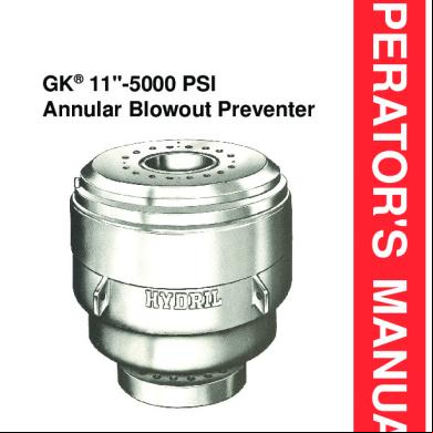
Hydril - Gk Bop.pdf 3w4a1g
October 2021 0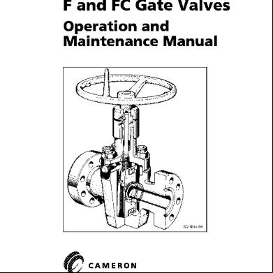
Cameron - F And Fc Gate Valves.pdf 3s4y6
December 2019 11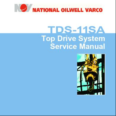
Tds-11sa Service Manual.pdf 5b3772
November 2019 21
2c82t
December 2020 0
Anais Nin Djeca Albatrosa 442zg
January 2021 0