Frame Relay 33sp
This document was ed by and they confirmed that they have the permission to share it. If you are author or own the copyright of this book, please report to us by using this report form. Report r6l17
Overview 4q3b3c
& View Frame Relay as PDF for free.
More details 26j3b
- Words: 1,354
- Pages: 31
Frame Relay Packet switching system with low overhead Assumes very reliable high-quality physical network Developed for use in ISDN networks Used widely in a variety of private and public networks which are not ISDN
1
X.25 Packet Flow Intermediate node 14
12 3
5
4
6 13
16
1
2
Source
15
11 9
8
7
Destination 2
10
Frame Relay Packet Flow Intermediate node
2
3
7
1
82
Source
6
5
4
Destination 3
Frame Relay Control Signalling carried on separate logical connection from data Multiplexing and switching of logical connections take place at layer 2 not layer 3 No hop-by-hop flow control or error control Protocol functionality at -network interface is reduced Large increase in throughput over X.25
4
Frame Relay Protocol Architecture
Control Plane
Plane
Plane
Q.931/Q.933
Control Plane Q.931/Q.933
-selectable TE functions
-selectable TE functions
LAPD (Q.921)
LAPD (Q.921) LAPF core (Q.922)
PhysicalI.430/I.431
LAPF core (Q.922) I.430/I.431Physical
5
Control Plane Protocols
Q.933 protocol is used for control of connections In ISDN, Control signalling uses LAPD protocol It is also possible to use in-channel call control using Q.933 on top of Q.922
6
Plane Protocols
LAPF (Q922) used for data transfer between s LAPF Core functions: – – – –
Frame delimiting, alignment, transparency Frame multiplexing / de-multiplexing Frame integrity checking ( size, byte count, errors) Congestion control
Functions are a sub-layer of data link layer They provide a bare frame transfer service 7
Frame Relay and X.25
X.25
Implemented by end system and network
Implemented by end system not network LAPF control
LAPB LAPF core
I.430/I431
Implemented by end system and network
I.430/I431
8
Frame Relay Call Control Subscriber must first be connected to a frame handler This is called an access connection When access connection is made, multiple logical channels can be multiplexed on the connection These are called frame relay connections They can be on-demand or semi-permanent
9
Frame Relay Call Control Two types of access connection
Switched Access – on switched network where exchange does not have frame handling capability – Exchange provides switched access (demand or semipermanent) to remote frame handler
Integrated Access – connected to pure frame relay network or switched network with integrated frame handling in local exchange – has direct logical access to frame handler 10
Access Switched access connection
TE
NT
ET
ET
FH
Semi-permanent access connection
Switched access
TE
NT
ET
Integrated access
FH
Local exchange
11
Frame Relay Connections Analogous to virtual circuit in X.25 Can be established when access connection established to frame handler Multiple connections ed over single link
– Called data link connections
Each connection has a unique Data link connection identifier (DLCI) 12
Frame Relay Connections
Data transfer sequence – Establish logical connection between two endpoints and assign unique DLCI – Exchange information in data frames - each frame has a DLCI – Release logical connection
13
Frame Relay Connections
Establishment and release of Logical connection is made by messages over dedicated call control logical connection with DLCI =0
14
Frame Relay Control Signalling NT Setup D-channel Q.931 exchange to establish B-channel circuitswitched connection B-channel Q.933 exchange to establish B-channel frame mode connection
Frame Relay Network
ISDN
Connect Connect ack Setup
Setup Connect Connect ack
Setup Connect
Connect ack
NT
Connect Connect ack
Frame relay Q.922 exchange of data on B-Channel
15 Message exchange for switched access to frame handler over ISDN
Frame Relay Control Signalling NT
Frame Relay NT Network Disconnect
ISDN Disconnect
B-channel Q.933 exchange to release B-channel framemode connection D-channel Q.931 exchange to release B-channel circuit switched connection
Release Release complete Disconnect Release Release complete
Release Release complete
Disconnect Release Release complete
16 Message exchange for terminating switched access to frame handler
LAPF Frame Format Flag Address 1 octet 2 - 4 octets
Information variable length
FCS 2 octets
Flag 1 octet
Frame Format
8
7
6
5
4
3
Upper DLCI Lower DLCI
FECN
BECN
2
1
C/R
EA 0
DE
EA 1
Address field 2 octets (default) Legend EA Address field extension bit C/R Command/response bit DE Discard eligibility bit
FECN Forward explicit congestion notification BECN Backward explicit congestion notification 17 DLCI Data link connection identifier
LAPF Frame Format No control field exists in the frame The connection can only carry data Therefore no in-band signalling exists No error control or flow control exists since there are no sequence numbers
18
LAPF Frame Format Address field carries DLCI Address field length may be extended to 2, 3, or 4 octets Length determined by EA bits - default is 2 octets DLCI allows multiple logical connections to be multiplexed on single channel DLCI can be 10, 17 or 24 bits depending on address field length 19
Congestion Control No in-channel control signalling means no sliding window flow control Congestion control is the t responsibility of the network and the end Network monitors congestion controls congestion by limiting flow of traffic at origin Network discards packets as a last resort 20
Congestion Control Techniques Type Discard Strategy
Congestion avoidance
Congestion avoidance
Congestion recovery
Technique
Function
Provides guidance to network about Discard Control which frames to discard Provides guidance Backward explicit to end-systems congestion about congestion notification in network Provides guidance Forward explicit to end-systems congestion about congestion notification in network implicit congestion notification
Key elements DE bit
BECN bit
FECN bit
End system infers Sequence numbers congestion from in higher-layer frame loss PDU
21
Discard Strategy
Network agrees to a connection at a certain data rate: – Committed information rate (CIR) in bps – Committed burst size (Bc) in bits over time T
Network also negotiates excess burst size (Be) the maximum amount of data in excess of Bc it will attempt to transfer in normal conditions 22
Discard Strategy Frame handler monitors traffic on a logical connection If data rate exceeds Bc in time interval T it will set DE bit and forward packet If data rate exceeds Bc+ Be in time interval T it will discard data
23
Discard Strategy Bits Transmitted
Discard Region Bc+Be
DE = 1 Region
Bc Access Rate
CIR
D = 0 Region Frame 1 DE=0
Frame 2 DE=0
Time Frame 3 DE=0 T
24
Discard Strategy Bits Transmitted
Discard Region Bc+Be
DE = 1 Region
Bc Access Rate
CIR
D = 0 Region Frame 1 DE=0
Frame 2 DE=1
Time Frame 3 DE=1
T
25
Discard Strategy Bits Transmitted
Discard Region Bc+Be
DE = 1 Region
Bc
Access Rate CIR
D = 0 Region Frame 1 DE=0
Frame 2 DE=1
Time Frame 3 Discard T
26
Congestion Avoidance Network alerts end-systems to growing congestion End-systems reduce offered load to network Two methods exist in frame relay
– Forward explicit congestion notification (FECN) – Backward explicit congestion notification (BECN)
27
Congestion Avoidance Two bits, FECN and BECN exist in each frame address field Any frame handler that detects may set either bit Any frame handler receiving a frame with a bit set must forward the frame with the bit set The bits therefore are signals to the end-
28
Congestion Avoidance The frame handler monitors outgoing queue lengths Determines average queue length If average exceed a threshold, then FECN bit or BECN bit or both is set They may be set for certain logical connections or all depending on queue sizes
29
Congestion Avoidance On receipt of BECN signal, reduces rate of frame transmission On receipt of FECN signal, notifies peer to reduce rate of frame transmission
30
Congestion Recovery When higher-level end-end protocol detects frame loss it assumes congestion This is called implicit signalling Flow control may be used to recover Gradual reduction of window size and gradual increase as frame loss disappears
31
1
X.25 Packet Flow Intermediate node 14
12 3
5
4
6 13
16
1
2
Source
15
11 9
8
7
Destination 2
10
Frame Relay Packet Flow Intermediate node
2
3
7
1
82
Source
6
5
4
Destination 3
Frame Relay Control Signalling carried on separate logical connection from data Multiplexing and switching of logical connections take place at layer 2 not layer 3 No hop-by-hop flow control or error control Protocol functionality at -network interface is reduced Large increase in throughput over X.25
4
Frame Relay Protocol Architecture
Control Plane
Plane
Plane
Q.931/Q.933
Control Plane Q.931/Q.933
-selectable TE functions
-selectable TE functions
LAPD (Q.921)
LAPD (Q.921) LAPF core (Q.922)
PhysicalI.430/I.431
LAPF core (Q.922) I.430/I.431Physical
5
Control Plane Protocols
Q.933 protocol is used for control of connections In ISDN, Control signalling uses LAPD protocol It is also possible to use in-channel call control using Q.933 on top of Q.922
6
Plane Protocols
LAPF (Q922) used for data transfer between s LAPF Core functions: – – – –
Frame delimiting, alignment, transparency Frame multiplexing / de-multiplexing Frame integrity checking ( size, byte count, errors) Congestion control
Functions are a sub-layer of data link layer They provide a bare frame transfer service 7
Frame Relay and X.25
X.25
Implemented by end system and network
Implemented by end system not network LAPF control
LAPB LAPF core
I.430/I431
Implemented by end system and network
I.430/I431
8
Frame Relay Call Control Subscriber must first be connected to a frame handler This is called an access connection When access connection is made, multiple logical channels can be multiplexed on the connection These are called frame relay connections They can be on-demand or semi-permanent
9
Frame Relay Call Control Two types of access connection
Switched Access – on switched network where exchange does not have frame handling capability – Exchange provides switched access (demand or semipermanent) to remote frame handler
Integrated Access – connected to pure frame relay network or switched network with integrated frame handling in local exchange – has direct logical access to frame handler 10
Access Switched access connection
TE
NT
ET
ET
FH
Semi-permanent access connection
Switched access
TE
NT
ET
Integrated access
FH
Local exchange
11
Frame Relay Connections Analogous to virtual circuit in X.25 Can be established when access connection established to frame handler Multiple connections ed over single link
– Called data link connections
Each connection has a unique Data link connection identifier (DLCI) 12
Frame Relay Connections
Data transfer sequence – Establish logical connection between two endpoints and assign unique DLCI – Exchange information in data frames - each frame has a DLCI – Release logical connection
13
Frame Relay Connections
Establishment and release of Logical connection is made by messages over dedicated call control logical connection with DLCI =0
14
Frame Relay Control Signalling NT Setup D-channel Q.931 exchange to establish B-channel circuitswitched connection B-channel Q.933 exchange to establish B-channel frame mode connection
Frame Relay Network
ISDN
Connect Connect ack Setup
Setup Connect Connect ack
Setup Connect
Connect ack
NT
Connect Connect ack
Frame relay Q.922 exchange of data on B-Channel
15 Message exchange for switched access to frame handler over ISDN
Frame Relay Control Signalling NT
Frame Relay NT Network Disconnect
ISDN Disconnect
B-channel Q.933 exchange to release B-channel framemode connection D-channel Q.931 exchange to release B-channel circuit switched connection
Release Release complete Disconnect Release Release complete
Release Release complete
Disconnect Release Release complete
16 Message exchange for terminating switched access to frame handler
LAPF Frame Format Flag Address 1 octet 2 - 4 octets
Information variable length
FCS 2 octets
Flag 1 octet
Frame Format
8
7
6
5
4
3
Upper DLCI Lower DLCI
FECN
BECN
2
1
C/R
EA 0
DE
EA 1
Address field 2 octets (default) Legend EA Address field extension bit C/R Command/response bit DE Discard eligibility bit
FECN Forward explicit congestion notification BECN Backward explicit congestion notification 17 DLCI Data link connection identifier
LAPF Frame Format No control field exists in the frame The connection can only carry data Therefore no in-band signalling exists No error control or flow control exists since there are no sequence numbers
18
LAPF Frame Format Address field carries DLCI Address field length may be extended to 2, 3, or 4 octets Length determined by EA bits - default is 2 octets DLCI allows multiple logical connections to be multiplexed on single channel DLCI can be 10, 17 or 24 bits depending on address field length 19
Congestion Control No in-channel control signalling means no sliding window flow control Congestion control is the t responsibility of the network and the end Network monitors congestion controls congestion by limiting flow of traffic at origin Network discards packets as a last resort 20
Congestion Control Techniques Type Discard Strategy
Congestion avoidance
Congestion avoidance
Congestion recovery
Technique
Function
Provides guidance to network about Discard Control which frames to discard Provides guidance Backward explicit to end-systems congestion about congestion notification in network Provides guidance Forward explicit to end-systems congestion about congestion notification in network implicit congestion notification
Key elements DE bit
BECN bit
FECN bit
End system infers Sequence numbers congestion from in higher-layer frame loss PDU
21
Discard Strategy
Network agrees to a connection at a certain data rate: – Committed information rate (CIR) in bps – Committed burst size (Bc) in bits over time T
Network also negotiates excess burst size (Be) the maximum amount of data in excess of Bc it will attempt to transfer in normal conditions 22
Discard Strategy Frame handler monitors traffic on a logical connection If data rate exceeds Bc in time interval T it will set DE bit and forward packet If data rate exceeds Bc+ Be in time interval T it will discard data
23
Discard Strategy Bits Transmitted
Discard Region Bc+Be
DE = 1 Region
Bc Access Rate
CIR
D = 0 Region Frame 1 DE=0
Frame 2 DE=0
Time Frame 3 DE=0 T
24
Discard Strategy Bits Transmitted
Discard Region Bc+Be
DE = 1 Region
Bc Access Rate
CIR
D = 0 Region Frame 1 DE=0
Frame 2 DE=1
Time Frame 3 DE=1
T
25
Discard Strategy Bits Transmitted
Discard Region Bc+Be
DE = 1 Region
Bc
Access Rate CIR
D = 0 Region Frame 1 DE=0
Frame 2 DE=1
Time Frame 3 Discard T
26
Congestion Avoidance Network alerts end-systems to growing congestion End-systems reduce offered load to network Two methods exist in frame relay
– Forward explicit congestion notification (FECN) – Backward explicit congestion notification (BECN)
27
Congestion Avoidance Two bits, FECN and BECN exist in each frame address field Any frame handler that detects may set either bit Any frame handler receiving a frame with a bit set must forward the frame with the bit set The bits therefore are signals to the end-
28
Congestion Avoidance The frame handler monitors outgoing queue lengths Determines average queue length If average exceed a threshold, then FECN bit or BECN bit or both is set They may be set for certain logical connections or all depending on queue sizes
29
Congestion Avoidance On receipt of BECN signal, reduces rate of frame transmission On receipt of FECN signal, notifies peer to reduce rate of frame transmission
30
Congestion Recovery When higher-level end-end protocol detects frame loss it assumes congestion This is called implicit signalling Flow control may be used to recover Gradual reduction of window size and gradual increase as frame loss disappears
31
Related Documents 171j1w

Frame Relay 33sp
July 2021 0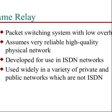
Frame Relay 33sp
August 2021 0
Frame Relay 33sp
December 2019 48
Tecnologia Frame Relay 2 6g4i1p
August 2022 0
Cisco - Frame Relay Pdf 3o1b20
June 2022 0
Frame Relay Y Atm 3d135h
January 2023 0More Documents from "Pk" 6d3k6j
Dsi Canada Dywidag Threadbar Imperial Units Ca 03 6p612j
October 2022 0
Specific Gravity Of Soil Solids 5d3z5e
November 2022 0
Analog Electronics Viva 71281e
November 2021 0
Surveying 6h5sx
November 2022 0
Habermas - The Philosophical Discourse Of Modernity 2p3f26
November 2019 151