Chain Surveying And Com Surveying 1r582t
This document was ed by and they confirmed that they have the permission to share it. If you are author or own the copyright of this book, please report to us by using this report form. Report r6l17
Overview 4q3b3c
& View Chain Surveying And Com Surveying as PDF for free.
More details 26j3b
- Words: 8,213
- Pages: 43
Surveying Definition of Surveying: 1. Surveying is the art of determining the relative position of points on, above or beneath the surface of the earth by means of direct or indirect measurement of distance, direction and elevation. 2. Surveying is a technique, profession and science of accurately determining the three dimensional position of points, the distance and angle between them. These points are usually on the surface of the earth and they are often used to establish land maps and boundaries for ownership. Primary division of survey. 1. Plane Surveying: It is that type of surveying in which the mean surface of the earth is considered as a plane and the spheroidal shape is neglected, all the triangles formed by survey lines are considered as plane triangles. Eg:
For 12km arc long line is only 1cm greater than subtended chord.
2. Geodetic surveying: It is that type of surveying in which the shape of the earth is taken into . All lines laying in the surface are curved lines and the triangles are spherical triangles.
Classification of Surveying 1. Classification based on the nature of the field survey * Land surveying * Topographical surveys * Cadastral surveys * City surveying * Marine or hydrographic surveying * Astronomical survey 2. Classification based on the object of survey * Engineering survey * Military survey * Mine Survey * Geological survey * Archeological survey 3. Classification based on instrument used * Chain survey * Theodolite survey * Traverse survey * Triangulation survey * Tachometric survey * Plane table survey * Photogrammetric survey * Aerial survey Principles of Surveying: 1. Location of a point by measurement from two points of reference: The relative position of the points to be surveyed should be located by measurement from at least 2 points of reference.
The position of which have already been fixed. Let A and B be the reference points on the ground. The distance AB can be measured accurately and the relative position of A and B can be plotted on the sheet to same scale. The A and B will survey as reference points for fixing the relative positions of other points. Any points such as C can be platted as follows.
2. Work from whole to part: The second principle of surveying is to work from whole to part. It is very essential to establish first a system of control points and to fix them with higher precision. Minor central points can then be established by less precise methods and the details can then be located using these minor central points by running minor traverse etc. The idea of working in this way is to prevent the accumulation of error and to control and localize minor error which otherwise, would expand to greater magnitude. If the reverse process is followed. Thus making me work uncontrollable at the end.
3. Chain Surveying: Chain Surveying is that type of survey in which only linear measurement are made in the field. This type of surveying is suitable for surveys of small extent. Principle of Chain Survey: The principle of chain survey is to provide a skeleton (or) frame work consisting of a number of connected triangles, as the triangle is the only simple figure that can be platted from the length of its sides measured in the field. To get a good result in platting, the framework should consist of triangles which are as nearly equilateral as possible. and definitions: Survey Stations: A survey station is a prominent points on the chain line and can be either at the beginning of the chain line or at the end of the chain line. Such station are known as main station. Survey lines: The line ing the main survey station are called main survey lines. The biggest of the main survey line is called the base line and the various survey station are platted with reference to base line. Check lines: The check lines (or) proof lines are the lines which are run is the field to check the accuracy of the work. Offset: It is the lateral distance of an object (or) ground features measured from a survey line. By method of offsets the points (or) object is located by measurement of a distance and angle from a points on the chain line. If the angle of offset is 90 0, it is
called perpendicular offset and if the angle is other than 900 it is called an oblique offset. Instruments for chaining: 1.Chain or tape, 2. Arrows, 3. Pegs, 4. Ranging rods, 5.Offset rod, 6. plumb bob.
1
Cross staff: The simple instrument used for setting out light angles is a cross staff. It consist of either a frame (or) box with two points of vertical slits and is mounted on a pole for fixing in the ground. Eg: (a) Open cross staff, (b) French cross staff, (c) Adjustable cross staff.
Optical square: Optical square is accurate instrument than the cross staff for setting out a line at right angle to other line. It consist of circular box with three slits at E, F and G. In line with the opening E and G a glass is silvered at the top and un-silvered at the bottom, is fixed facing the opening E. opposite to the opening F a silver glass is fixed at A making an angle 450 to the previous glass. A ray from the ranging rod at Q es through the lower un-silvered portion of the mirror at B and is seen directly by eye at the slit E another ray from the object at P is received by the mirror at A and is reflected towards the mirror at B which reflects it towards the eye. Thus the image P and Q are visible at ‘B’. If both the image are in the same vertical line the line PD and QD will be at right angle.
Let the ray PA makes an angle α with the mirror at A. ACB = 450 or ABC = 1800 – (450+ α) = 1350 – α By law reflection Ebb1 = ABC = 1350 – α ABE = 1800 – 2 (1350-α) = 2α-900 DAB = 1800 – 2 α From ∆le ADB ADB=1800 – (2α - 900) – (1800-2α) ADB = 180 - 2α + 90 - 1800 + 2α = 900 thus if the image of P and Q lie is the same vertical line, then the line PD and QD will be at right angle to each other. Obstacle in chaining:Obstacle to chaining prevents chainman from measuring directly between 2 points and give raise to a set of problems in which distance are found by indirect measurements.
Obstacle to chaining are of three types 1. Obstacle to ranging but not chaining This type of obstacle in which the ends are not inter-visible is quite common except in flat country. There are 2 cases of this obstacle. Both ends of the line may be intervisible from intermediate points on the line. Both ends of the line may not be visible from intermediate points on the line.
2. Obstacle to chaining but not ranging: There are 2 cases of this obstacle When it is possible to chain round the obstacle ie. pond.
Methods (a): select 2 points A and B on either side. Set out equal perpendicular AC and BD. Measure CD then CD= AB
Methods (b): set out perpendicular to the chain line measure AC and BC the length of AB is calculated from the relation AB =
BC 2−¿ AC 2 √¿
Methods (c): By optical square (or) cross staff find a point which subtends 900 with A and B. measure AC and BC. Then the length of AB is AB =
AC 2−¿ BC 2 √¿
Methods (d): Select 2 points C and D to both side of ‘A’ and is the same line measure. AC, AD, BC and BD, let angle BCD be θ from ∆le BCD. BD2 = BC2 + CD2 – 2BC x CD Cos θ Cos θ =
BC 2 +CD 2−2 BD 2 ……………..1 2 BC x CD
Similarly from ∆le BCA Cos θ =
BC 2 + AC 2− AB 2 ……………….2 2 BC x AC
Equating equation 1 and 2 we get AB =Sqrt[
BC (¿¿ 2 x AD)+ ( BD 2 x AC ) CD ¿
– (AC x AD)]
Method (e): Select any point ‘E’ and base ‘C’ is line with ‘AE’ making AE=EC range ‘D’ in line with BE making BE=ED measure CD; then AB=CD Method (f): select any suitable point ‘E’ and measure AE and BE mark ‘E’ and D on AE and BE such that CE =
AE n
and DF =
Measure CD; then
AE n
AB = n x CD.
When it is not possible to chain round the obstacle eg. River. Method (a): select point ‘B’ on one side and A and C on the other side. erect AD and CE as perpendicular to ‘AB’ and range B, D and E in one line. Measure AC, AD and CE. If a line DF is drawn parallel to AB and AB, cutting CE in F perpendicularly. Then the ∆le ABD and FDE will be similar. AB AD
=
DF FE
FE = CE - CF = CE – AD and DF = AC AB AD
AC
= CE−AD AC x AD
AB = CE− AD Method (b): erect perpendicular AC and bisect it at D. erect perpendicular CE at ‘C’ and Range ‘E’ in line with BD measure CE then AB = CE Method (c ) : erect a perpendicular AC at A and choose any convenient point ‘C’ with the help of an optical square, fix a point ‘D’ on a chain line in such a way that BCD is a right angle. Measure AC and AD. ∆le ABC and DAC are similar hence
AB AC
=
AC AD
; AB =
AC 2 AD
Method (d): fix point ‘C’ in such a way that it subtends 900 with AB. Range ‘D’ in line with AC and make AD=AC. At ‘D’ erect a perpendicular DE to cut the line in ‘E’ then AB = AE
3. Obstacle to both ranging and chaining.
Choose 2 points A and B to one side and erect perpendicular AC and BD of equal length CD and Prolong it the obstacle. Choose two points E and F on ‘CD’ and erect perpendicular EG and FH equal to that of AC. GH and prolong it measure DE evidently BG= DE. Problems: 1. A chain line ABC crosses a river, B and C being on the near and distant bank respectively. The respective bearing of C and A taken at ‘D’, a point 45m measured at right angles to AB from B are 300 0 and 2100, AB being 24m find the width of the river. Bearing of DC = 3000 Bearing of DA = 210 BD = 45m, AB = 24m ADC = Bearing of DC – Bearing DA ADC = 300 – 210 ADC= 900 24
BDA = 45 BDA = 280 A1 BDC = 900 – 280 A1 = 610551
From ∆ BDC BC = BD --- (BDC) = 45 – (610551) BC = 84.375 Assessment 1. In ing an obstacle is the form of a pond stations A and D, on the main line, were taken on the posit sides of the pond. On the left of AD, a line AB 225m long was laid down and a second line AC. 275m long, was longed on the right of AD, the points B, D and ‘C’ being in the same slight line. BD and DC were than chained and found to be 125 m and 137.5m resp. find the length AD Ans:212.9m Error due to incorrect chain: If the length of the chain used in measuring length of the line is not equal to the true length, the measured length of the line will not be correct and suitable correction will have to be applied. If the chain is too long, the measured distance. Will be less. The error will be negative and the correction is positive. Similarly if it is too short, the measured distance will be more, the error will be positive and correction is negative. Let L = true length of the chain (or) tape L1=Incorrect length of the chain (or) tape. 1. Correction to measured length l1 = measured length of the line l = actual length of the line 1
True length of line = measured length of line x L1 l=l ( L ) 1
2. Correction to Area A1= measured (or) computed area of the ground A = actual (or) true area of the ground
L L
1
Then true area = measured area x
l 2 ¿ l ¿
1
l 2 ¿ l ¿
A = A1 l1 L
L+ ∆ L L
=
=1+
∆L L
∆L= error in length of chain Let
∆L L
=e
(l + e) 2 = l + 2e + e2 = l + 2e (if e is small) A = (1 + 2c) A1 3. Correction to volume: V1 = measured (or) computed volume V= actual (or) true volume Then, true volume = measured volume x L1 3 ¿ L ¿
V = V1 1
L L
∆L L
L1 3 ¿ L ¿
=
L+ ∆ L L
=1+
∆L L
=e
1
L 3 ¿ L V =¿
x V = (1 + e) 3 V
(1+e)3= 1+e3+3e2+3e2+3e= (1+3e) V =( 1+3 e ) v if e is small
Problem: 1. The length of a line measure with a 20m chain was found to be 250m. Calculate the true length of the line if the chain was 10 cm too long.
1
In correct --- of the chain = L = 20 +
10 100
= 20.1m
Measured length = l1 = 250m 1
Hence =length of the line = l
L L
1
20.1 = 250 ( 20 ) = 251.25m
2. The length of the survey line was measured with a 20m chain and was fond to be equal to 1200m. As a check the length was again measured with a 25m chain and was fond to be 1212m. On comparing the 20m chain with the test gauge. It was found to be 1 decimates too long. Find the actual length of the 25m chain used. Sol with 20m chain = L1 = 20 + 0.10 = 20.1m 1
L=l
L L
1
= 1200 x
20.1 20
= 1026m (true length of line)
1
With 25m chain= l= 1026 = L1 =
L1 25
L L
x l1
1212
1206 x 25 1212
= 24.88m
Thus the 25m chain was 12 cm too short. Error in chaining: A cumulative error is that which occur in the same direction and tends to accumulate. A compensating error may occur is either direction and hence tends to compensate. 1. 2. 3. 4. 5. 6.
Error Incorrect length of tape Bad ranging Tape not stretched tight and straight, but both ends in line. Tape not stretched horizontally Error due to temperature Variation in pull
Type cumulative cumulative
Sign + (or) – +
cumulative cumulative cumulative compensating
+ + + (or) – ±
7. Error due to sag 8. Error is marking tape length 9. Disturbing arrows after they are set. 10.Error in reading the tape 11.Incorrect counting of chain length
cumulative compensating Blunder Mistake Blunder
+ ±
Tape correction: We have seen the different sources of errors in line or measurement. In most of the error, proper correction can be applied. Since in most of the cases a tape is used for precise work the correction are sometimes called tape correction. After having measured length, the correct length of the base is calculated by applying the following correction. 1. Correction for absolute length: It is the usual practice to express the absolute length of a tape as its nominal or designated length plus (or) minus a correction. The correction for the measured length is Ca =
L.C l
Where Ca = correction for absolute length L = measured length of a line (m) C = correction per tape length l = designated length of the tape (m) The sign of correction (Ca) will be the same as that of ‘C’, 2. Correction for temperature: If the temperature in the field is more than the temperature at which the tape was standardized, the length of the tape increases, measured distance become less and the correction is therefore additive. Similarly if the temperature is less the length of the tape decreases, measured distance become more and the correction is negative. the temperature correction is given by Ct = α(Tm – To) L Where: α = Co-efficient of thermal expansion
Tm = Mean temperature is the field during measurement To = Temperature during standardization of the tape L = measured length (tape length) 3. Correction for pull (or) tension: If the pull applied during measurement is more than the pull at which the tape was standardize, the length of the tape increases, measured distance become less and the correction is positive. Similarly if the pull in less, the length of the tape decreases. The measured distance become more and the correction is negative If is the correction for pull we have ( P m−P0 ) L = AE Pm = pull applied during measurement (N) Po = standard pull (N) L = measured length (m) A = C/s area of the tape (cm2) F = young’s modulus of elasticity (N/cm2) 4. Correction for sag: When the tape is stretched on s between two points. It takes the form of a horizontal catenary. The horizontal distance will be less than the distance along curve. The difference between horizontal distance and the measured length along catenary is called the sag correction. l1 = length of the tape (in meter) suspended between A and B Cs1=sag correction in m w= weight of the tape in kg/m p= pull applied in kg wl1= weight of the tape suspended between the The relation between curved length (l1) and the chord length (d1) of a very flat parabola is given by 8 l1 = d1 [ 1+ 3
h [ d 1 ] 2]
Cs1 = d1 - l1 =
−8 3
h2 d1
Note: sag correction in always negative Correction for slope or vertical alignment The distance measured along the slop is always greater than the horizontal distance and hence the correction is negative AB = L = inclined length measured AB1 = horizontal distance h = difference is elevation between the ends Cv = slop correction 2
Cv =
h 2L
Problems: 1. A line was measured with a steel tape which was exactly 30m long at 18 0C and found to be 452.343m the temperature during measurement was 32 0C. Find the true length of the line. Take the co-efficient of expansion of the tape per 0C = 0.0000035 Solution Given: Temperature correction per tape length Ct = α(Tm – To) l l = 30m, To = 180C, Tm=320C α = 0.0000035 Ct = 0.0000035 x [32-18] x 30=0.00147m Hence the length of the tape at 320c = 30+Ct = 30.00149m Now true length of a line = measured length x
L1 L
L = 30m, L1 = 30.00147m, aMeasured length = 452.343m True Length =
30.00147 30
x 452.343 = 452.365m
2. A line was measured with a steel tape which was exactly 30m at 18 oC and a pull of 5 kg and the measured length was 459.242m. Temperature during measurement was 280c and pull applied was 10kg the tape was uniformly ed during the measurement. Find the true length of the line. if the cross sectional area of the tape was 0.02cm 2 the co-efficient of expression per 10C=0.0000035 and the E = 2.1 x 10⁶ kg / cm2 Solution: Correction for temperature per tape length= α(Tm-To)L = 0.0000035 (28-18) x 30 = 0.00105 (+ve) sag correction per tape length = 0 ( P m−P0 ) L Correction for pull per tape length = AE (10−5) x 30 = 0.02 x 2.1 x 10 6
= 0.00357m (+ve) Total correction = 0.00105 + 0.00357 = 0.00462m True length of the tape = 30.00462m True length of the line =
30.00462 30
x 459.242 = 459.949, 459.313
3. A 50m tape is suspended between the ends under pull of 15 kg. The weight of the tape is 1.5kg find the corrected length of the tape between its ends. Solution: 2
Correction for sag = Cs =
l1 w p 24 p
2
l1 = 50m, w = 1.5kg, p=15kg Cs =
50 x 1.5 2 24 x 152
= 0.0208m
Corrected length of the tape = l-Cs = 50-0.0208 = 49.9792m 4. A steel tape 20m long standardized at 550F with a pull of 10kg was used for measuring a base line. Find the correction per tape length. If the temperature at the time of measurement was 80 0F and the pull exerted was 16kg. Weight
of 1 cubic cm of steel = 7.86g. weight of tape =0.8kg, and E = 2.109 x 10 6 kg / cm2, Co- efficient of expansion of tape per 10F = 6.2x 10⁻⁶ Solution: Correction for temperature = 20x6.2 x 10-6 (80-55) = 0.0031m (additive) p (¿ ¿ m− po ) x L AE ¿
Correction for pull =
Weight of tape = A (20x100) (7.86x10⁻³) kg = 0.8kg A= =
0.8 7.86 x 2
= 0.051cm2
( 16−10 ) 20 0.051 x 2.109 x 106
Correction for sag =
= 0.00112 (additive)
wl ¿ ¿ 1¿ 2 ¿ = 1¿ l¿ ¿
2
20 (0.8) 24 x 162
= 0.00208m (Subtractive)
Total correction = 0.0031 + 0.00112 – 0.00208 = 0.00214m 5. A steel tape is 30m long at a temperature of 65 oF when laying horizontally on the ground its sectional area is 0.082cm2, its weight 2kg and the coefficient of expansion 65 x 10-7 per 10F. The tape is stretched over three equal span. Calculate the actual length between the end gradations under the following condition; temperature = 850F, pull = 18kg, take E = 2x10⁶ kg / cm2 Ans: 30.005m (Assignment)
Com surveying Introduction: Chain surveying can be used when the area to be surveyed is comparatively small and is fairly flat. When large areas involved, methods of chain surveying is not sufficient. In such cases it is required to use some angle measuring instruments for the survey lines to be observed. Definition: Com surveying may be defined as that branch of surveying in which the position of an object is determined by angular measurement using com. Instruments for the direct measurement of directions: 1. Surveying’s com 2. Prismatic com Instrument for measurement of angles 1. Sextant 2. Theodolite Bearing and angle: The direction of a survey line can either be established a) with relation to each other b) with relation to any meridian Bearing: bearing of a line is its direction relative to a given meridian ie. true, magnetic and arbitrary meridian
1. True meridian: True meridian through a point is the line in which a plane, ing that point and the north and south pole and intersects with surface of the earth. 2. True bearing: True bearing of a line is the horizontal angle which it makes with the true meridian (through one of the extremities of the line). Since the direction of true meridian remains fixed hence the true bearing of a line is constant. 3. Magnetic meridian: Magnetic meridian through a point is the direction shown by a freely floating balanced magnetic needle free from all other attractive forces. The direction of magnetic meridian can be established by magnetic com. 4. Magnetic Bearing: The magnetic bearing of a line is the horizontal angle which it makes with magnetic meridian. The magnetic com used to measure it. 5. Arbitrary meridian: it is any convenient direction towards a permanent and prominent mark or signal such as church spire, top of chimney, light horse etc. 6. Arbitrary Bearing: Arbitrary bearing is a line is the horizontal angle which it makes with any arbitrary meridian a theodolite is used to measure. Systems of bearing: There are two types of bearing system 1. Whole circle bearing system (W.C.B) or azimuthal system In this system the bearing of a line is measured with magnetic north (or with south) is clock wise direction. the value of the bearing thus varies from 00-3600. Prismatic com is graduated on this system.
From figure This WCB of AB = θ1, of AC is θ2 of AD = θ3 of AF = θ4 2. The Quadrantal bearing system: (Reduced bearings) In this system the Bearing of a line is measured eastward or westward from north or south whichever is nearer. The direction can be either clock wise or anticlockwise depending upon the position of the line. By surveyor’s com. This system can be observed.
The QB of line AB is α and is written as NαE, the bearing is measured W.R.T, north meridian (since it is nearer) towards east. Conversion of bearing from one system to the others: Conversion from WCB to RB Line
WCB
Rule For R.B
Quadrat
AB AC AD
BETWEEN 0 and 900 900 and 1800 1800 and 2700
RB = WCB RB = 1800 – WEB RB = WCB – 180o
NE SE SW
AF 2700 and 3600 Conversion from RB to WCB Line AB AC AD AF
RB NαE SβE SθW N ϕ W
RB = 3600 – WCB Rule For ECB WCB = RB WEB= 1800 – RB WCB= 180o+RB WCB= 3600 –RB
NW WCB BETWEEN 0 and 900 900 and 1800 1800 and 2700 2700 and 3600
Fore bearing (FB) and back bearing (BB): The bearing of a line whether expressed in WCB or in QB system, differs according to the observation is made from one end of the line or from the other. Eg: if the bearing of a line AB is measured from A towards B, if is known as fore bearing as forward bearing. If the bearing of the line AB is measured from ‘B’ towards ‘A’, it is known as back bearing or backward bearing.
In the WCB system the back bearing of a line many be obtained from the fore bearing by BB= FB ± 1800 Use + sign if the given fore bearing is less than 180 0 and use ‘-’ sign is exceeds 1800. In QB system the FB and BB are numerically equal but with opposite letters. The BB of a line may therefore obtained by simple substuting N for S and S for N and E for W and W for E. thus, if the fore bearing of line CD is N40 0251E the back bearing of CD is S400 251W. Examples:
I) Convert the following WCB to QB 0 1. 68 321 -WCB ----- N 680 321 E QB 2. 1320121 -WCB QB = 180 – WCB = 180 – 1320121 = 470481 QB = S470481E 3. 2360371 QB = WCB – 180 QB = 2360371 – 180 = 560371 QB = 5560371W 4. 3340521 QB=360 – WCB = 360 – 3340521 = 25081 QB = N 25081W II) Convert the following RB in WCB a) N360161 E → 360161 b) S280141E → 1510461 c) S 470281W → 2270261 d) N580241W → 360-580241=3010361 III) The following are absorbed for bearing AB 38 0141; BC, 1420181; CD, 2080371; and DE, 3180261 find there BB Solution: FB of AB = 380141 BB of AB = 380141 + 180 = 2180141 FB of BC = 1420181 BB of AB = 180 + 1400181 = 3320181 FB of CD = 2080371 BB of AB = 2080371 – 180 = 280371 FB of DE = 31800261 BB of DE = 3180261 – 180 = 1380261 IV) The fore bearing of line are as follows AB, N32 0121E; CD, S260301W find their BB FB AB N320121E CD S260301W Calculation of angles from bearing:
BB S320121W N260301E
Case I: when the bearing of two lines measured from the point of intersection of the line are given Rule → FB of one line – FB of other
Case II: when bearing of 2 lines are given ⋉ = (180 + θ ) - θ 1 2 ⋉ = BB of previous line – FB of next line
Problem: Following bearing were observed with a com calculate the interior angles. Line FB AB 600301 BC 122001 CD 46001 DE 2050301 EA 300001 Included angle = bearing of previous line – Bearing of next line Angle A= Bearing of AE-Bearing of AB
= (3000-1800) – 600301=590301 Angle B = Bearing of BA – Bearing of BC = (60o301 + 1800) – 122o = 1180301 Angle C = Bearing of CB – Bearing of CD = (172o + 1800) -46o =2560 Angle D = Bearing of DC – Bearing of DE = (46o +180) – 2050301 Angle E = Bearing of FD – Bearing of EA =(2050201 – 1800) -300o +3600 = 850301 Sum of all angles = 540000 Check: (2n-4)900 = (10-4) 90 = 5400 3. The bearing of the sides of a traverse ABCDE are as follows. Line AB BC CD DE EA
FB 1070151 22001 2810301 1890151 1240451
Compute the interior angles of the traverse. Bearing of AE = BB of EA = 3040451 FB of AB = 1070151 = 1970301 Exterior angle Angle A = 3600 – 1970301 = 162o301 Bearing of BA = BB of AB = 2870151 FB of BC = 22001 =2650151 Exterior angle Angle B = 3600-2650151= 940451 Bearing of CB = BB of BC = 202001 FB of CD = 2810301 = 790301 = Interior angle Angle C = 790301 Bearing of DC = BB of CD = 1010301 FB of DF = 1890151 870451 interior angle Angle D = 870451 Bearing of FD = BB of DE = 9o51
BB 2870151 202001 1010301 90151 3040451
FB of EA = 1240451 1150301 interior angle Angle E = DEA = 1150301 Check Sum of angles = 5400 and (2n-4) 90=540 3.The following interior angles were measured with a sextant in a closed traverse. The bearing of the line AB was measured as 600 with a prismatic com. Calculate the bearing of all other line if ∟A = 140 0101 ∟B=90081, ∟C=600221, ∟D=699201 Note: To find the bearing of a line, add the measured clockwise angle to that bearing of the previous line. If the sum is more than 180 0, deduct 1800. If is sum is less than 1800, add 1800. clockwise angle will be obtained if we proceed in the anticlockwise direction round the traverse. Starting with A---- D, C, B Bearing of AD = bearing of BA + 1400101-1800 = (180 + 60) + 1400101 – 180 = 200010 Bearing of DC = bearing of AD + 690201 – 1800 = 2000101 + 690201 -1800 = 890301 Bearing of CB = Bearing of DC + 600201 + 1800 = 890301 + 600201 - 1800 = 3290521 Bearing of BA = bearing of CB + 90081 - 180 = 3290521 + 90081 – 180 = 2400 Then Bearing of AB = 2400 – 1800 = 600 (Check) Assignment: Determine the value of included angle in the closed com traverse ABCD conducted is the clockwise direction, given the following fore bearing of their respective line and apply the check.
Line AB BC CD DA
FB 400 700 2100 2800
The prismatic com: The prismatic com is the most convenient and portable form of magnetic com which can either be used as a hand instrument or can be fitted on a tripod. The magnetic needle is attached to the circular ring made of aluminum a nonmagnetic substance. When the needle is on the rivet, it will orient itself. In the magnetic meridian and therefore the north and south ends of the ring will be in this direction the line of sight is defined by the object vane and the eye slit, both attached to the com box, the object vane consist of vertical hair attached to a suitable frame while the eye slit consist of a vertical slit cut into the upper assembly of the prism unit. Both being hinged to the box. When an object is sighted, the sight vanes will rotate W.R.T the N-S end of ring through an angle which the two line makes with the magnetic meridian. A triangular prism in fitted below the eye slit, having suitable arrangement for focusing to suit different eye sights. The 00 or 3600 reading is engraved on the south end of the ring. So that bearing of the magnetic meridians read as 00. The reading increases in clockwise direction from 0 0 at south end to 900 at west end, 1800 at north end and 2700 at east end. The greatest advantage of prismatic com is that both sighting the object as well as the reading circle can be done. Simultaneously without changing the position of eye. Adjustment of prismatic com a) Temporary adjustments b) Permanent adjustment s
Temporary adjustment: Temporary adjustment are those adjustment which have to be made at every set up of the instrument. 1. Centering: Centering is the process of keeping the instrument exactly over the station. Ordinary prismatic com is not provided with fine centering device as it is generally fitted to engineer’s theodolite. The centering is invariable done by adjusting the legs of the tripod. A plumb bob may be used to Judge the centering and if it is not available, it may be judge by dropping a pebble from the center of the bottom of the instrument 2. Leveling: If the instrument is a hand instrument it must be held in hand in such a way that graduated disc is swinging freely and appears to be level. Generally a tripod is provided with ball and socket arrangement with the help of which the tap of the box can he levelled. 3. Focusing the prism: The prism attachment is slided up or down for focusing till the reading are seen to the sharp and clear. The surveyor’s com: In surveyor’s com the graduated ring is directly attached to the box and not with needle. The needle freely floats over the pivot thus the graduated ring is not oriented in the magnetic meridian. The object vane is similar to that of prismatic com. The eye vane consist of a simple metal vane with fine slit. The objects is to be sighted first and the reading is then taken against the north end of the needle, by looking vertically through the top glass. When the line of sight is in magnetic meridian the north and south ends of the needle will be over 00 N and 00 S graduations of the graduated card. The card is graduated in quadrantal system having 00 at N and S end and 90 0 at east and west ends. Magnetic Declaration: Magnetic declination at a place is the horizontal angle between the true meridian and the magnetic meridian shown by the needle at the time of observation.
If the magnetic meridian is to the right side or eastern side of the true meridian, declination is said to be eastern or +ve. If is to be the left side or western side the declination is said to be western or –ve
The lines drawn through the points of same declination are called isogonic line. The line made up of points having zero declination are called agonic line.
Example: 1. The magnetic bearing of a line AB is S320E and the magnetic declination is 80161E what is the true bearing of a line. True bearing of AB = magnetic bearing AB ± declination Convert given QB to WEB WCB of AB = 180-32=1480 True bearing of AB = 1480+8o161 = 1560161 In QB = S230441E Local attraction: A magnetic meridian at a place is established by a magnetic needle which is uninfluenced by other attracting forces. However, sometimes the magnetic needle may the attracted and prevented from indicating the true magnetic meridian. Local attraction is a term used to denote any inference, such as the attracting forces, which prevents the needle from pointing to the magnetic north is given locality. Detection of local attraction:
The local attracting at a particular place can be detected by observing the fore and back bearing of each line and finding the difference. If the difference between fore and back bearing in 1800, it may the taken that both the station are free from local attraction, provided there are no observational and instrumental error. Elimination of local attraction: First method: In the first method true included angle at the affected stations are computed from the observed bearing. Commencing from the in unaffected line and using these included angles, the correct bearing of the successive lines are competed. Example: The observed bearing of a lines AB, BC, CD and DA are Line AB BC CD DA
FB 460101 1190201 1690301 2800201
BB 2260101 2980401 3510101 990201
Solution: Difference for BB and FB of line AB = 2260101 – 460101 =1800 A and B are free from local attraction ∟A = Bearing of AD – Bearing of AB = 990201 – 460101 = 530101 ∟B = Bearing of BA – Bearing of BC = 2260101 – 1190201 = 1060501 Similarly ∟C = 1290101, ∟D = 700501 Check A + B + C + D = 3600 Commencing from the unaffected line AB. The correct bearings of the other lines may be calculated. Bearing AD = Bearing of BA + 530101 = 2260101 + 530101 – 180 = 990201 Bearing of DC = Bearing of AD + ∟D = 990201 + 700501 + 180 = 3500101 Bearing of CB = Bearing of DC + ∟C = 3500101 + 1290101 – 1800 = 2990201 Bearing of BA = Bearing of CB + ∟B = 2990201 + 1060501 – 1800 = 22600101 Corrected bearings are: Line AB BC CD
FB 460101 1190201 1700101
BB 2260101 2990201 3500101
2790201
DA
990201
2. The following bearings were observed in running a closed traverse. Line AB BC CD DE EA
FB 1910151 1200451 349051 3390351 2960001
BB 10051 3000451 690000 1600401 1150001
Calculate the interior angles and correct them for observational errors. Taking the bearing of BC as correct, find the corrected bearing of the remaining side. Solution: The difference between the FB of next line and BB of previous line will gives the angle ∟A = FB of AB – BB of EA = 1910151 – 1150 = 760151 ∟B = FB of BC – BB of AB = 1200451 – 100151 = 1100301 ∟C = FB of CD = BB of BC = 349051 - 3000451 = 480201 ∟D = FB of DE – BB of CD = 3390351 – 1690001 = 1700351 ∟E = FB of EA – BB of DE = 296001 – 1600401 = 1350201 Total = 5410001 Then by (2n-4) x 90 = (2x5-4) x 90 = 5400 The discrepancy = 5410 – 5400 = +10 Distributing error equally among 5 angles ∟A = 760151 – 121 = 76031 ∟B = 1100301 121 = 1100181 ∟C = 480201 – 121 = 48081 ∟D = 1700351 – 121 = 1700231 ∟E = 1350201 – 121 = 135081 5400001 Starts from the correct BB of BC Calculate as before 2nd method: It is in most common use the included angles are not computed but the amount and direction of error due to local attraction at each of the affected station is found starting from bearing unaffected by local attraction, the bearing of
the successive lines are adjusted by applying the correction to the observed bearing. Example: The following bearing were are observed while traversing with a com Line AB BC CD DE
Line
Observed
AB BA BC CB CD DC DE ED
bearing 450451 2260101 960551 277051 290451 2090101 3240481 1440481
FB 450451 960551 290451 3240481
Correction
-
0 at A 251at B 251at B 351at C 351 at C 0 at D 0 at D 0 at E
BB 2260101 277051 2090101 1440481
Corrected
Remark
450451 2250451 960301 2760301 290101 2090101 3240481 1440481
Station B and C are affected Local attraction
3. The following bearings were observed in running a closed traverse Line AB BC CD DE EA
FB 75051 1150201 1650351 2240501 3040501
BB 2540201 2960351 3450351 44051 125051
At what station do you served the local attraction? Determine the correct magnetic bearing. If declination was 50101E, what are the true bearings? Line
Observed bearing
Correction
Corrected
+50101E ---
Bearing
bearing
Remark
AB BA BC CB CD DC DE ED EA AE
75051 2540201 1150201 2960351 1650351 3450351 2240501 44051 3040501 125051
+00301 +10151 +10151 O at C O at C O at D O at D + O0451 + O0451 + O0301
750351 2550351 1160351 2960351 1650351 3450351 2240501 440501 3050351 1250351
800451 260451 1210451 3010451 1700451 3500451 230001 50001 3100451 1300451
Station A, B and E are affected by local Attraction
4. Assignment: The following fore and back bearing were observed in traversing with com. Where LA was suspected? Line FB BB 0 1 AB 38 30 2190151 BC 1000451 2780301 Cd 250451 2070151 DE 3250151 145015 Find the corrected fore and back bearings and the true bearing of each of the lines given that the magnetic declination was 100W. Co-ordinate method of platting for a froverse survey. If the length and bearing of a survey line are known, it can be represented on plane by 2 rectangles co-ordinates. The axis of the co-ordinates are the north and south line and east and west line. The latitude of survey line many be defined as its co-ordinate length measured parallel to the meridian direction. The departure of the survey line may be defined as its co-ordinates length measured at perpendicular to the meridian direction.
In fig the length of the line OA is given by l 1 and bearing of line OA is θ 1 then latitude L1 = +l1 cos θ1 and D1 = l1 sin θ1 WCB 0 to 90
0
900 to 1800 1800 to 2700 2700 to 3600
RB and Quadrent NθE → I S θ E → II SθW
→
III
Sign of Latitude Departure + + -
+
-
-
+
-
N θ W → IV Omitted measurements: In order to have a check on field work and in order to balance a traverse the length and direction of each line is generally measured in the field. Sometimes when it is not possible to take all measurements due to obstacles or because of some over sights such omitted measurement or missing quantities can
be calculated by latitudes and departure provided the quantities required are not more than two. For closed traverse ƸL and ƸD are Zero ƸL = l1 cos θ1 + l2 cos θ2 + 13 cos θ3 +……………….. = 0 ED = l1 sin θ1 + l2 sin θ2 + l3 sin θ3 + …………. = 0 Where l1, l2, l3…………. Are length of line and θ 1, θ2, θ3………….. are reduced bearings.
Given l1 ,θ
Required l
Formula l = l cas θ
l, θ
D
D = l sinθ
L1, D
Tan θ
Tan θ = D/L
L1, θ
l
l = L sec θ
D1, θ
l
l = D cosec θ
L1, l
Cas θ
Cos θ = L/l
D1,l
Sin θ
Sin θ = D/l
L, D
l
l=
√ D 2 + L2
Cases of omitted measurement Case I: Bearing or length or bearing and length of one side omitted
To calculate, bearing or length or bearing and length of line EA Calculate ƸL1 and ƸD1 of the four known sides AB, BC, CD, DE then ƸL = Latitude of EA + ƸL1 = 0 ED = Departure of EA + ƸD1 = 0 Departure of EA = -ƸD1 Knowing the latitude and departure of the line EA the length and bearing are calculated Case II: Length of one side and bears of another side omitted.
Let the length of DE and Bearing of EA be omitted DA which become the closing line of the traverse ABCD is which all quantities are known. Now Length and bearing can be calculated as in first case. In ∆ADE, the length of sides DA and EA are known and angle ADE is known. The angle β and length DE can be calculated.
Sin B = DE =
DA EA
sin ⋉ and ⋎ =180 - (B + ⋉ )
EA sin ⋎ sin ⋉
= DA
sin ⋎ sin B
Knowing ⋎ , the bearing of EA can be calculated Case III:Length of two sides omitted:
Length DE and EA be omitted the length and bearing of the closing line can be calculated by the 1st case. The angle
α
β,
⋎
can be calculated by knowing
bearing, length of DE of EA can be computed by ∆DEA DE =
sin ⋎ sin β
sin α
EA = sin β
x DA x DA
Problems: 1. The table below gives the length and bearing of the line of a traverse ABCDE and the length and bearing of EA having been omitted. Calculate the length and bearing of the line EA. Line AB BC CD DE EA
Length 204.0 226.0 187.0 192.0 ?
Bearing 870301 200201 280001 2100301 ?
The latitude and departure of lines AB, BC, CD, DE are calculated as under. Latitude + 8.9 211.92 32.48 165.44 253.3 165.44
Line AB BC CD DE Sum
Departure + 203.80 78.52 184.16 97.44 282.32 281.60
ƸL1 = +87.86 ƸD1 = +0.72 Latitude of EA = -ƸL1 = -87.86m Departure EA = -ƸD1 = -0.72m Since the latitude and departure of line EA is –ve The line in the S- W quadrant the reduced bearing of EA is given by Tan θ =
D L
=
0.72 0 87.86 = 0 281
Bearingof EA= S 0o281= 1800281 lat
87.86
Also length of EA = caso = cas o o 281 = 87.85m 2. A closed traverse was conducted round an obstacle and the following observations were made work out the missing quantity Side AB BC CD DE EA
Length (M) 500 620 468 ? ?
Azimuth 980301 300201 2980301 230001 1500101
Solution: The latitude and departure of closing line DA is calculated as below. Line AB BC
Latitude + 535.11
73.91
departure + 494.5 313.11
CD Sum
223.45 758.56 73.91 1 ƸL +684.55
411.29 807.61 411.29 1 ƸD = 396.32
Latitude of DA = - 684.55 SW
Departure of DA = - 396.32 Θ of DA is given by Tan θ =
D L
396.32
= 684.55 =
θ= 30041 Bearing DA = S 30041 W or 2100041 Length of DA = l = L sec θ = 684.55 sec 30041 = 791.01m From figure ∟ADE = ⋉ = 230001 – 210041 = 19056 ∟DEA =
β
= 1500101 – (2300-180) = 1000101
∟DAE = γ 1800 – (190561 – 1000101) = 590541 From ∆ ADE using sine rule we get sin γ
DE = DA sin β
= 695.27m
sin γ sin β
= 273.99m
EA = DA
Errors in com survey: The errors may be classified as a) Instrumental error 1. The needle not being perfectly straight 2. Pivot being bent 3. Sluggish needle 4. blunt pivot point 5. Improper balancing weight 6. Plane of sight not being vertical 7. Line of sight not ing through the center of the sight b) Personal errors: 1. Inaccurate leveling of the com box 2. Inaccurate centering
3. Inaccurate bisection of signals 4. Carelessness is reading and recording c) Natural errors: 1. Variation of dedication 2. Local affection 3. Magnetic changes in atmosphere due to clouds and storms etc. Graphical method of adjusting com traverse: For a rough survey such as com traverse the Bowditch rule may be applied graphically. According to the graphical method, it is not necessary to calculate latitude and departure etc. before plotting the traverse directly from the field notes, the angle or bearing may be adjusted to satisfy the geometric condition of the traverse.
In fig (a) polygon A B1 C1 D1 E1 A1 an unbalanced traverse having a closing error equal to A1A. The total closing error A1A is distributed linearly to all the sides in proportion to their length by a graphical construction shown in fig (b). In fig (b) AB1, B1C1, C1D1, D1E1 etc. represents the length of the sides of the traverse either to the same scale as that of fig (a) or to a reduced scale. The ordinate aA1 is made equal to closing error A1A, by constructing similar triangle corresponding error bB1, cC1, dD1, eE1 are found. In fig (a), lines E 1E, D1D, C1C, B1B are drawn parallel to the closing error A1A and made equal to eE1, dD1, cC1,
bB1 respectively. The polygon ABCDE thus obtained represents the adjusted traverse. It should note that the ordinates bB1, cC1, eE1, aA1 in fig (b) represents the corresponding error in magnitude only but not in direction.
Related Documents 171j1w
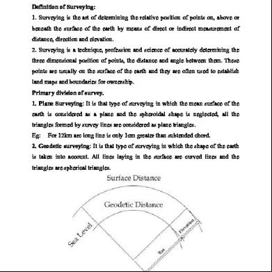
Chain Surveying And Com Surveying 1r582t
November 2021 0
Chain Surveying 1f1i3p
October 2021 0
Com Types In Surveying 15581t
October 2019 54
Surveying 6h5sx
November 2022 0
Surveying 6h5sx
December 2020 0
Chain Surveying Report d3n33
November 2021 0More Documents from "Lalith Koushik Ganganapalli" 543d3n

Importance Of Hydrology 2b2u29
November 2019 62
Chain Surveying And Com Surveying 1r582t
November 2021 0
Plc Soft Master Ml200 5356y
February 2022 0
Arm_system_developer_s_guide_deg_and_optimizing_system_software_chapter_2_arm_processor_fundamentals.pdf 436k5n
November 2019 23
Vxworks And Embedded Linux.ppt 6t642b
April 2021 0