Basics Of Communication Systems 2y1f8
This document was ed by and they confirmed that they have the permission to share it. If you are author or own the copyright of this book, please report to us by using this report form. Report r6l17
Overview 4q3b3c
& View Basics Of Communication Systems as PDF for free.
More details 26j3b
- Words: 4,443
- Pages: 14
UCCN2043 – Lecture Notes
1.0
Basics of Communication Systems
We begin the journey into the exciting field of telecommunications by studying the basic building blocks of a telecommunication system. We will study the various types of communication and how the electrical signal is impaired as it travels through the transmission medium. With the advances in digital electronics, digital communication systems slowly are replacing analog systems. We will discuss the differences between analog communication and digital communication. 1.1
Basic Telecommunication System
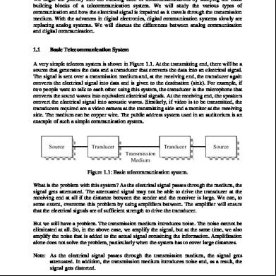
A very simple telecom system is shown in Figure 1.1. At the transmitting end, there will be a source that generates the data and a transducer that converts the data into an electrical signal. The signal is sent over a transmission medium and, at the receiving end, the transducer again converts the electrical signal into data and is given to the destination (sink). For example, if two people want to talk to each other using this system, the transducer is the microphone that converts the sound waves into equivalent electrical signals. At the receiving end, the speakers convert the electrical signal into acoustic waves. Similarly, if video is to be transmitted, the transducers required are a video camera at the transmitting side and a monitor at the receiving side. The medium can be copper wire. The public address system used in an auditorium is an example of such a simple communication system.
Source
Tranducer
Tranducer
Source
Transmission Medium Figure 1.1: Basic telecommunication system. What is the problem with this system? As the electrical signal es through the medium, the signal gets attenuated. The attenuated signal may not be able to drive the transducer at the receiving end at all if the distance between the sender and the receiver is large. We can, to some extent, overcome this problem by using amplifiers between. The amplifier will ensure that the electrical signals are of sufficient strength to drive the transducer. But we still have a problem. The transmission medium introduces noise. The noise cannot be eliminated at all. So, in the above case, we amplify the signal, but at the same time, we also amplify the noise that is added to the actual signal containing the information. Amplification alone does not solve the problem, particularly when the system has to cover large distances. Note: As the electrical signal es through the transmission medium, the signal gets attenuated. In addition, the transmission medium introduces noise and, as a result, the signal gets distorted.
Page 1 of 14
UCCN2043 – Lecture Notes The objective of deg a communication system is for the electrical signal at the transmitting end to be reproduced at the receiving end with minimal distortion. To achieve this, different techniques are used, depending on issues such as type of data, type of communication medium, distance to be covered, and so forth.
Figure 1.2 shows a communication system used to interconnect two computers. The computers output electrical signals directly (through the serial port, for example), and hence there is no need for a transducer. The data can be ed directly through the communication medium to the other computer if the distance is small (less than 100 meters).
Figure 1.2: PC-to-PC communication. Note: The serial ports of two computers can be connected directly using a copper cable. However, due to the signal attenuation, the distance cannot be more than 100 meters.
Figure 1.3 shows a communication system in which two PCs communicate with each other over a telephone network. In this system, we introduced a new device called a modem (modulator-demodulator) at both ends. The PCs send digital signals, which the modem converts into analog signals and transmits through the medium (copper wires). At the receiving end, the modem converts the incoming analog signal into digital form and es it on to the PC.
Figure 1.3: PC-to-PC communication over telephone network.
Figure 1.4 shows a generic communication system. In this figure, a block "medium access processing" is introduced. This block has various functions, depending on the requirement. In some communication systems, the transmission medium needs to be shared by a number of s. Sometimes the is allowed to transmit only during certain time periods. Sometimes the may need to send the same data to multiple s. Additional processing needs to be done to cater to all these requirements. At the transmitting side, the source generates information that is converted into an electrical signal. This signal, called the baseband signal, is processed and transmitted only when it is allowed. The signal is sent on to the transmission medium through a transmitter. At the receiving end, the receiver amplifies the signal and does the necessary operations to present the baseband signal to the . Any telecommunication system is a special form of this system. Consider the following examples: Page 2 of 14
UCCN2043 – Lecture Notes
Figure 1.4: Generic communication system.
In the case of a radio communication system for broadcasting audio programs, the electrical signal is transformed into a high-frequency signal and sent through the air (free space). A radio transmitter is used to do this. A reverse of this transformation — converting the highfrequency signal into an audio signal — is performed at the receiving station. Since it is a broadcasting system, many receivers can receive the information. In a communication system on which two persons communicate with two other persons located somewhere else, but only on one communication link, the voice signals need to be combined. We cannot mix the two voice signals directly because it will not be possible to separate them at the receiving end. We need to "multiplex" the two signals, using special techniques. In a mobile communication system, a radio channel has to be shared by a number of s. Each has to use the radio channel for a short time during which he has to transmit his data and then wait for his next turn. This mechanism of sharing the channel is known as multiple access. Hence, depending on the type of communication, the distance to be covered, etc., a communication system will consist of a number of elements, each element carrying out a specific function. Some important elements are: •
Multiplexer: Combines the signals from different sources to transmit on the channel. At the receiving end, a demultiplexer is used to separate the signals.
•
Multiple access: When two or more s share the same channel, each has to transmit his signal only at a specified time or using a specific frequency band.
•
Error detection and correction: If the channel is noisy, the received data will have errors. Detection, and if possible correction, of the errors has to be done at the receiving end. This is done through a mechanism called channel coding.
Page 3 of 14
UCCN2043 – Lecture Notes •
Source coding: If the channel has a lower bandwidth than the input signal bandwidth, the input signal has to be processed to reduce its bandwidth so that it can be accommodated on the channel.
•
Switching: If a large number of s has to be provided with communication facilities, as in a telephone network, the s are to be connected based on the numbers dialed. This is done through a mechanism called switching.
•
Signaling: In a telephone network, when you dial a particular telephone number, you are telling the network whom you want to call. This is called signaling information. The telephone switch (or exchange) will process the signaling information to carry out the necessary operations for connecting to the called party.
Note: Two voice signals cannot be mixed directly because it will not be possible to separate them at the receiving end. The two voice signals can be transformed into different frequencies to combine them and send over the medium.
1.2
Types Of Communication
Based on the requirements, the communications can be of different types: Point-to-point communication: In this type, communication takes place between two end points. For instance, in the case of voice communication using telephones, there is one calling party and one called party. Hence the communication is point-to-point. Point-to-multipoint communication: In this type of communication, there is one sender and multiple recipients. For example, in voice conferencing, one person will be talking but many others can listen. The message from the sender has to be multicast to many others. Broadcasting: In a broadcasting system, there is a central location from which information is sent to many recipients, as in the case of audio or video broadcasting. In a broadcasting system, the listeners are ive, and there is no reverse communication path. Simplex communication: In simplex communication, communication is possible only in one direction. There is one sender and one receiver; the sender and receiver cannot change roles. Half-duplex communication: Half-duplex communication is possible in both directions between two entities (computers or persons), but one at a time. A walkie-talkie uses this approach. The person who wants to talk presses a talk button on his handset to start talking, and the other person's handset will be in receive mode. When the sender finishes, he terminates it with an over message. The other person can press the talk button and start talking. These types of systems require limited channel bandwidth, so they are low cost systems. Full-duplex communication: In a full-duplex communication system, the two parties—the caller and the called — can communicate simultaneously, as in a telephone system. However, note that the communication system allows simultaneous transmission of data, but when two persons talk simultaneously, there is no effective communication! The ability of the communication system to transport data in both directions defines the system as full-duplex.
Page 4 of 14
UCCN2043 – Lecture Notes Depending on the type of information transmitted, we have voice communication, data communication, fax communication, and video communication systems. When various types of information are clubbed together, we talk of multimedia communications. Even a few years ago, different information media such as voice, data, video, etc. were transmitted separately by using their own respective methods of transmission. With the advent of digital communication and "convergence technologies," this distinction is slowly disappearing, and multimedia communication is becoming the order of the day. 1.3
Transmission Impairments
While the electrical signal is traversing over the medium, the signal will be impaired due to various factors. These transmission impairments can be classified into three types: (a) Attenuation distortion (b) Delay distortion (c) Noise 1.3.1
Attenuation Distortion
The amplitude of the signal wave decreases as the signal travels through the medium. This effect is known as attenuation distortion. 1.3.2
Delay Distortion
Delay distortion occurs as a result of different frequency components arriving at different times in the guided media such as copper wire or coaxial cable. 1.3.3
Noise
Noise can be divided into the following categories: • Thermal noise • Intermodulation • Crosstalk • Impulse noise Thermal noise: Thermal noise occurs due to the thermal agitation of electrons in a conductor. This is distributed uniformly across the spectrum and hence called white noise. This noise cannot be eliminated and hence, when deg telecom systems, we need to introduce some method to overcome the ill effects of thermal noise. Thermal noise for a bandwidth of 1 Hz is obtained from the formula: N0 = kT where N0 is noise power density, in watts per Hz k is Boltzmann's constant, with the value 1.3803 x 10⁻²³ J/K and T is temperature in Kelvin (K). Page 5 of 14
UCCN2043 – Lecture Notes Thermal noise for a bandwidth of B Hz is given by N = kTB (watts) If N is expressed in dB (decibels) N = 10 log k + 10 log T + 10log B dB watts = -228.6 + 10 log T + 10 log B Using this formula, thermal noise for a given bandwidth is calculated
Note: Thermal noise for a bandwidth of B Hz is given by N = kTB (watts) where k is Boltzmann's constant and T is temperature. N is generally expressed in decibels.
Intermodulation noise: When two signals of different frequencies are sent through the medium, due to nonlinearity of the transmitters, frequency components such as f1 + f2 and f1 – f2 are produced, which are unwanted components and need to be filtered out. Crosstalk: Unwanted coupling between signal paths is known as crosstalk. In the telephone network, this coupling is quite common. As a result of this, we hear other conversations. Crosstalk needs to be eliminated by using appropriate design techniques. Impulse noise: This is caused by external electromagnetic disturbances such as lightning. This noise is unpredictable. When the signal is traversing the medium, impulse noise may cause sudden bursts of errors. This may cause a temporary disturbance in voice communication. For data communication, appropriate methods need to be devised whereby the lost data is retransmitted. Note: Impulse noise occurs due to external electromagnetic disturbances such as lightning. Impulse noise causes burst of errors. Noise is the source of bread and butter for telecom engineers! If there were no noise, there would be no need for telecom engineers — for we can then design perfect communication systems. Telecom engineering is all about overcoming the effects of noise.
Page 6 of 14
UCCN2043 – Lecture Notes
1.4
Analog versus Digital Transmission
The electrical signal output from a transducer such as microphone or a video camera is an analog signal; that is, the amplitude of the signal varies continuously with time. Transmitting this signal (with necessary transformations) to the receiving end results in analog transmission. However, at the receiving end, it has to be ensured that the signal does not get distorted at all due to transmission impairments, which is very difficult. The output of a computer is a digital signal. The digital signal has a fixed number of amplitude levels. For instance, binary 1 can be represented by one voltage level (say, 5 volts) and binary 0 can be represented by another level (say, 0 volt). If this signal is transmitted through the medium (of course with necessary transformations), the receiving end needs only to detect these levels. Even if the signal is slightly impaired due to noise, still there is no problem. For example, we can say that if the signal is above 2.5 volts, it is 1 and if it is below 2.5 volts, it is zero. Unless the signal is badly damaged, we can easily find out whether the transmitted bit is a 1 or a 0. The voice and video signals (output of the transducer) are always analog. To take advantage of the digital transmission, we have to convert the analog signal into the digital format. This is achieved through analog-to-digital conversion. At this point, let us assume only that it is possible to convert an analog signal into its equivalent digital signal. We will study the details of this conversion process in later chapters. Digital transmission is much more advantageous than analog transmission because digital systems are comparatively immune to noise. Due to advances in digital electronics, digital systems have become cheaper, as well. The advantages of digital systems are: • • • •
More reliable transmission because only discrimination between ones and zeros is required. Less costly implementation because of the advances in digital logic chips. Ease of combining various types of signals (voice, video, etc.). Ease of developing secure communication systems.
Though a large number of analog communication systems are still in use, digital communication systems are now being deployed. Also, the old analog systems are being replaced by digital systems. In this course, we focus mainly on digital communication systems. Note: All the newly developed communication systems are digital systems. Only in broadcasting applications, is analog communication used extensively.
Page 7 of 14
UCCN2043 – Lecture Notes
1.5
Digital Communications
So what is digital communication? Definitions vary, but the simplest one is that it is the communication (or transmission) of a message using a finite alphabet (symbol set) during a finite time interval (symbol interval). As such the raising of an eyebrow, a wink, the nod of one’s head or a shoulder shrug may be considered to be digital communications. Some examples of primitive but meaningful digital communication systems: • The Roman army used shields and the sun to flash signals over line-of-sight distances; • North American natives used smoke signals; • Ancient Chinese soldiers use smoke and fire in the beacon towers of the Great Wall to signal the approaches of enemy. Modern communication systems started with the “harnessing” of electricity. This harnessing, which began in the mid-eighteenth century, meant that communication at distances further than one could see or hear became feasible. Table 1.1 shows some of the principal events in the development of electronic communications over the last century and a half. It all started by the ideas of sending a series of electrostatic charges over appropriate wire to represent letters in the alphabet. The subsequent introduction of Morse Code in the year 1837 marks the beginning of electronic communication era (which happened to be digital). Until 1875, all rapid long distance communication depended upon the telegraph, in essence digital communication with only text messages being transmitted. But in 1877 the telephone was invented by Alexander Graham Bell and this heralded the arrival of long distance analog communications. Coupled with Hertz’s discovery of the propagation of electromagnetic waves and Marconi’s subsequent exploitation of this phenomenon to greatly increase communication distances, analog communication was dominant for most of the twentieth century. However, the second half of the twentieth century, particularly the last two decades, saw a resurgence in digital communications. In 1948 Claude Shannon published a landmark paper in which he showed that by using digital communications it was possible even in the presence of noise to achieve a vanishingly small error probability at a finite communication rate (or finite bandwidth) and with finite signal power. At approximately the same time, R. W. Hamming proposed the Hamming codes for error detection and correction of digital data. The invention of the transistor, also in 1948, and subsequent development of integrated circuitry provided the last component for a digital communications resurrection. Initially digital communication systems were developed for deep space communications where data reliability was paramount and cost of lesser consideration. Analog communication was still dominant and the first mobile telephone system introduced in North America in the 1980s was analog based. But the ever increasing integrated chip densities follows by the decrease in cost meant that the intensive signal processing required by digital communications became feasible. The late 1980s and the last decade of the twentieth century saw several digital communication systems developed. Ever since then, digital communications dominant until now. Page 8 of 14
UCCN2043 – Lecture Notes
Table 1.1: Important events in the history of electronic communications. Page 9 of 14
UCCN2043 – Lecture Notes 1.6
Digital Communications System Design & Equipments
In the design of a communication system, the important objectives are often to minimize the following: • Equipment cost • System complexity • Power consumption • Bandwidth occupied by the signal • Transmission time Bandwidth is a measure of how rapidly the information-bearing part of a signal can change and is therefore an important parameter for communication system design. Table 1.2 compares the nominal bandwidth of three common types of information signal. Efficient use of bandwidth and transmission time ensures that as many subscribers as possible can be accommodated within the constraints of these limited, and therefore valuable, resources. Information Signal
Bnadwidth
Speech telephony
4 KHz
High quality radio (sound) broadcast
15 KHz
TV broadcast (video)
6 MHz
Table 1.2: Comparison of nominal bandwidths for several information signals.
The component parts of a hypothetical digital communications transceiver (transmitter/receiver) are shown in Figure 1.5. The transceiver in the figure has been chosen to include all the elements commonly encountered in digital communications systems. Not all transceivers will employ all of these elements though. 1.6.1
CODEC
At its simplest, a transceiver CODEC (coder/decoder) consists of an analogue to digital converter (ADC) in the transmitter, which converts a continuous analogue signal into a sequence of codewords represented by binary voltage pulses, and a digital to analogue converter (DAC) in the receiver, which converts these voltage pulses back into a continuous analogue signal.
Page 10 of 14
UCCN2043 – Lecture Notes
Figure 1.3: Hypothetical digital communications transceiver
Page 11 of 14
UCCN2043 – Lecture Notes The ADC consists of a sampling circuit, a quantiser and a pulse code modulator. • The sampling circuit provides discrete voltage samples taken, at regular intervals of time, from the analogue signal. • The quantiser approximates these voltages by the nearest level from an allowed set of voltage levels. (It is the quantisation process which converts the analogue signal to a digital one). • The PCM encoder converts each quantised level to a binary codeword, digital ones and zeros each being represented by one of two voltages. • An anti-aliasing filter is sometimes included prior to sampling in order to reduce distortion that can occur as a result of the sampling process. In the receiver’s DAC… • The received binary voltage pulses are converted to quantised voltage levels by a PCM decoder which is then smoothed by a low filter to reconstruct (at least a good approximation to) the original analogue signal.
Digitisation of analogue signals usually increases the signal’s transmission bandwidth but it permits reception at a lower signal-to-noise ratio than would otherwise be the case. This is an example of how one resource (bandwidth) can be traded off against another resource (transmitter power). CODECs make widespread use of sophisticated digital signal processing techniques to encode efficiently the signal prior to transmission and also to decode the received signals when they are corrupted by noise, distortion and interference. This increases transceiver complexity, but allows higher fidelity, repeatable, almost error-free transmission to be achieved. 1.6.2
Source, Security and Error Control Coding
In addition to PCM encoding and decoding a CODEC may have up to three additional functions. • Firstly (in the transmitter), it may reduce the number of binary digits (bits) required to convey a given message. This is source coding and can be thought of as effectively removing redundant digits. • Secondly, it may encrypt the source coded digits using a cipher for security. This can yield both privacy (which assures the sender that only those entitled to the information being transmitted can receive it) and authentication (which assures the receiver that the sender is who they claim to be). • Finally, the CODEC may add extra digits to the (possibly source coded and/or encrypted) PCM signal, which can be used at the receiver to detect, and possibly correct, errors made during symbol detection. This is error control coding and has the effect of incorporating binary digits at the transmitter which, from an information point of view, are redundant.
Page 12 of 14
UCCN2043 – Lecture Notes In some ways, error control coding, which adds redundancy to the bit stream, is the opposite of source coding, which removes redundancy. Both processes may be employed in the same system, however, since the type of redundancy which occurs naturally in the information being transmitted is not necessarily the type best suited to detecting and correcting errors at the receiver. The source, security and error control decoding operations in the receiver, are the inverse of those in the transmitter. 1.6.3
Multiplexers
In digital communications, multiplexing is often performed to accommodate several simultaneous transmissions. One of the common multiplexing techniques is time division multiplexing (TDM). Time division multiplexers interleave either PCM codewords, or individual PCM binary digits, to allow more than one information link to share the same physical transmission medium (which can be cable, optical fibre or a radio frequency channel). If communication is to occur in real time this implies that the bit rate of the multiplexed signal is at least N times that of each of the N-tributary PCM signals, and this in turn implies an increased bandwidth requirement. The requirement for an increase in bandwidth comes from the fact that the transmitted signal now comprises shorter duration pulses, which have a wider spectral response. Demultiplexers split the received composite bit stream back into its component PCM signals. 1.6.4
MODEM
MODEMs (modulators/demodulators) condition binary pulse streams so that the information they contain can be transmitted over a given physical medium, at a given rate, with an acceptable degree of distortion, in a specified or allocated frequency band. The modulator in the transmitter may change the voltage levels representing individual, or groups of, binary digits. Typically, the modulator also performs the following: • Shapes, or otherwise filters, the resulting pulses to restrict their bandwidth • Shifts the entire transmission to a convenient allowed frequency band. The input to a modulator is thus a baseband digital signal whilst the output is often a band waveform. The demodulator in a receiver reconverts the received waveform into a baseband signal. • Equalisation corrects (as far as possible) signal distortion that may have occurred during transmission. • Detection converts the demodulated baseband signal into a binary symbol stream. • The matched filter, shown as one component of the detector in Figure 1.3, represents one type of signal processing that can be employed, prior to the final digital decision process, in order to improve error performance. Page 13 of 14
UCCN2043 – Lecture Notes 1.6.5
Multiple Access
Multiple access refers to those techniques, and/or rules, which allow more than one transceiver pair to share a common transmission medium (e.g. one optical fibre, one satellite transponder, one piece of coaxial cable or one radio frequency channel). Several different types of multiple access techniques are currently in use, each type having its own advantages and disadvantages. The multiple access problem is essentially one of efficient and (in some sense) equitable sharing of the limited resource represented by the transmission medium. 1.7
Advantages of Digital Communications
Digital communications systems usually represent an increase in complexity over the equivalent analogue systems. Despite that, digital communications have become the preferred option for most new systems and, in many instances, have replaced existing analogue systems. Some of the reasons are listed below: • Increased demand for data transmission. • Increased scale of integration, sophistication and reliability of digital electronics for signal processing, combined with decreased cost. • Facilitate source coding for data compression. • Possibility of channel coding (line, and error control coding) to minimise the effects of noise and interference. • Ease with which bandwidth, power and time can be traded off in order to optimise the use of these limited resources. • Standardisation of signals, irrespective of their type, origin or the services they , leading to an integrated services digital network (ISDN).
Page 14 of 14
1.0
Basics of Communication Systems
We begin the journey into the exciting field of telecommunications by studying the basic building blocks of a telecommunication system. We will study the various types of communication and how the electrical signal is impaired as it travels through the transmission medium. With the advances in digital electronics, digital communication systems slowly are replacing analog systems. We will discuss the differences between analog communication and digital communication. 1.1
Basic Telecommunication System
A very simple telecom system is shown in Figure 1.1. At the transmitting end, there will be a source that generates the data and a transducer that converts the data into an electrical signal. The signal is sent over a transmission medium and, at the receiving end, the transducer again converts the electrical signal into data and is given to the destination (sink). For example, if two people want to talk to each other using this system, the transducer is the microphone that converts the sound waves into equivalent electrical signals. At the receiving end, the speakers convert the electrical signal into acoustic waves. Similarly, if video is to be transmitted, the transducers required are a video camera at the transmitting side and a monitor at the receiving side. The medium can be copper wire. The public address system used in an auditorium is an example of such a simple communication system.
Source
Tranducer
Tranducer
Source
Transmission Medium Figure 1.1: Basic telecommunication system. What is the problem with this system? As the electrical signal es through the medium, the signal gets attenuated. The attenuated signal may not be able to drive the transducer at the receiving end at all if the distance between the sender and the receiver is large. We can, to some extent, overcome this problem by using amplifiers between. The amplifier will ensure that the electrical signals are of sufficient strength to drive the transducer. But we still have a problem. The transmission medium introduces noise. The noise cannot be eliminated at all. So, in the above case, we amplify the signal, but at the same time, we also amplify the noise that is added to the actual signal containing the information. Amplification alone does not solve the problem, particularly when the system has to cover large distances. Note: As the electrical signal es through the transmission medium, the signal gets attenuated. In addition, the transmission medium introduces noise and, as a result, the signal gets distorted.
Page 1 of 14
UCCN2043 – Lecture Notes The objective of deg a communication system is for the electrical signal at the transmitting end to be reproduced at the receiving end with minimal distortion. To achieve this, different techniques are used, depending on issues such as type of data, type of communication medium, distance to be covered, and so forth.
Figure 1.2 shows a communication system used to interconnect two computers. The computers output electrical signals directly (through the serial port, for example), and hence there is no need for a transducer. The data can be ed directly through the communication medium to the other computer if the distance is small (less than 100 meters).
Figure 1.2: PC-to-PC communication. Note: The serial ports of two computers can be connected directly using a copper cable. However, due to the signal attenuation, the distance cannot be more than 100 meters.
Figure 1.3 shows a communication system in which two PCs communicate with each other over a telephone network. In this system, we introduced a new device called a modem (modulator-demodulator) at both ends. The PCs send digital signals, which the modem converts into analog signals and transmits through the medium (copper wires). At the receiving end, the modem converts the incoming analog signal into digital form and es it on to the PC.
Figure 1.3: PC-to-PC communication over telephone network.
Figure 1.4 shows a generic communication system. In this figure, a block "medium access processing" is introduced. This block has various functions, depending on the requirement. In some communication systems, the transmission medium needs to be shared by a number of s. Sometimes the is allowed to transmit only during certain time periods. Sometimes the may need to send the same data to multiple s. Additional processing needs to be done to cater to all these requirements. At the transmitting side, the source generates information that is converted into an electrical signal. This signal, called the baseband signal, is processed and transmitted only when it is allowed. The signal is sent on to the transmission medium through a transmitter. At the receiving end, the receiver amplifies the signal and does the necessary operations to present the baseband signal to the . Any telecommunication system is a special form of this system. Consider the following examples: Page 2 of 14
UCCN2043 – Lecture Notes
Figure 1.4: Generic communication system.
In the case of a radio communication system for broadcasting audio programs, the electrical signal is transformed into a high-frequency signal and sent through the air (free space). A radio transmitter is used to do this. A reverse of this transformation — converting the highfrequency signal into an audio signal — is performed at the receiving station. Since it is a broadcasting system, many receivers can receive the information. In a communication system on which two persons communicate with two other persons located somewhere else, but only on one communication link, the voice signals need to be combined. We cannot mix the two voice signals directly because it will not be possible to separate them at the receiving end. We need to "multiplex" the two signals, using special techniques. In a mobile communication system, a radio channel has to be shared by a number of s. Each has to use the radio channel for a short time during which he has to transmit his data and then wait for his next turn. This mechanism of sharing the channel is known as multiple access. Hence, depending on the type of communication, the distance to be covered, etc., a communication system will consist of a number of elements, each element carrying out a specific function. Some important elements are: •
Multiplexer: Combines the signals from different sources to transmit on the channel. At the receiving end, a demultiplexer is used to separate the signals.
•
Multiple access: When two or more s share the same channel, each has to transmit his signal only at a specified time or using a specific frequency band.
•
Error detection and correction: If the channel is noisy, the received data will have errors. Detection, and if possible correction, of the errors has to be done at the receiving end. This is done through a mechanism called channel coding.
Page 3 of 14
UCCN2043 – Lecture Notes •
Source coding: If the channel has a lower bandwidth than the input signal bandwidth, the input signal has to be processed to reduce its bandwidth so that it can be accommodated on the channel.
•
Switching: If a large number of s has to be provided with communication facilities, as in a telephone network, the s are to be connected based on the numbers dialed. This is done through a mechanism called switching.
•
Signaling: In a telephone network, when you dial a particular telephone number, you are telling the network whom you want to call. This is called signaling information. The telephone switch (or exchange) will process the signaling information to carry out the necessary operations for connecting to the called party.
Note: Two voice signals cannot be mixed directly because it will not be possible to separate them at the receiving end. The two voice signals can be transformed into different frequencies to combine them and send over the medium.
1.2
Types Of Communication
Based on the requirements, the communications can be of different types: Point-to-point communication: In this type, communication takes place between two end points. For instance, in the case of voice communication using telephones, there is one calling party and one called party. Hence the communication is point-to-point. Point-to-multipoint communication: In this type of communication, there is one sender and multiple recipients. For example, in voice conferencing, one person will be talking but many others can listen. The message from the sender has to be multicast to many others. Broadcasting: In a broadcasting system, there is a central location from which information is sent to many recipients, as in the case of audio or video broadcasting. In a broadcasting system, the listeners are ive, and there is no reverse communication path. Simplex communication: In simplex communication, communication is possible only in one direction. There is one sender and one receiver; the sender and receiver cannot change roles. Half-duplex communication: Half-duplex communication is possible in both directions between two entities (computers or persons), but one at a time. A walkie-talkie uses this approach. The person who wants to talk presses a talk button on his handset to start talking, and the other person's handset will be in receive mode. When the sender finishes, he terminates it with an over message. The other person can press the talk button and start talking. These types of systems require limited channel bandwidth, so they are low cost systems. Full-duplex communication: In a full-duplex communication system, the two parties—the caller and the called — can communicate simultaneously, as in a telephone system. However, note that the communication system allows simultaneous transmission of data, but when two persons talk simultaneously, there is no effective communication! The ability of the communication system to transport data in both directions defines the system as full-duplex.
Page 4 of 14
UCCN2043 – Lecture Notes Depending on the type of information transmitted, we have voice communication, data communication, fax communication, and video communication systems. When various types of information are clubbed together, we talk of multimedia communications. Even a few years ago, different information media such as voice, data, video, etc. were transmitted separately by using their own respective methods of transmission. With the advent of digital communication and "convergence technologies," this distinction is slowly disappearing, and multimedia communication is becoming the order of the day. 1.3
Transmission Impairments
While the electrical signal is traversing over the medium, the signal will be impaired due to various factors. These transmission impairments can be classified into three types: (a) Attenuation distortion (b) Delay distortion (c) Noise 1.3.1
Attenuation Distortion
The amplitude of the signal wave decreases as the signal travels through the medium. This effect is known as attenuation distortion. 1.3.2
Delay Distortion
Delay distortion occurs as a result of different frequency components arriving at different times in the guided media such as copper wire or coaxial cable. 1.3.3
Noise
Noise can be divided into the following categories: • Thermal noise • Intermodulation • Crosstalk • Impulse noise Thermal noise: Thermal noise occurs due to the thermal agitation of electrons in a conductor. This is distributed uniformly across the spectrum and hence called white noise. This noise cannot be eliminated and hence, when deg telecom systems, we need to introduce some method to overcome the ill effects of thermal noise. Thermal noise for a bandwidth of 1 Hz is obtained from the formula: N0 = kT where N0 is noise power density, in watts per Hz k is Boltzmann's constant, with the value 1.3803 x 10⁻²³ J/K and T is temperature in Kelvin (K). Page 5 of 14
UCCN2043 – Lecture Notes Thermal noise for a bandwidth of B Hz is given by N = kTB (watts) If N is expressed in dB (decibels) N = 10 log k + 10 log T + 10log B dB watts = -228.6 + 10 log T + 10 log B Using this formula, thermal noise for a given bandwidth is calculated
Note: Thermal noise for a bandwidth of B Hz is given by N = kTB (watts) where k is Boltzmann's constant and T is temperature. N is generally expressed in decibels.
Intermodulation noise: When two signals of different frequencies are sent through the medium, due to nonlinearity of the transmitters, frequency components such as f1 + f2 and f1 – f2 are produced, which are unwanted components and need to be filtered out. Crosstalk: Unwanted coupling between signal paths is known as crosstalk. In the telephone network, this coupling is quite common. As a result of this, we hear other conversations. Crosstalk needs to be eliminated by using appropriate design techniques. Impulse noise: This is caused by external electromagnetic disturbances such as lightning. This noise is unpredictable. When the signal is traversing the medium, impulse noise may cause sudden bursts of errors. This may cause a temporary disturbance in voice communication. For data communication, appropriate methods need to be devised whereby the lost data is retransmitted. Note: Impulse noise occurs due to external electromagnetic disturbances such as lightning. Impulse noise causes burst of errors. Noise is the source of bread and butter for telecom engineers! If there were no noise, there would be no need for telecom engineers — for we can then design perfect communication systems. Telecom engineering is all about overcoming the effects of noise.
Page 6 of 14
UCCN2043 – Lecture Notes
1.4
Analog versus Digital Transmission
The electrical signal output from a transducer such as microphone or a video camera is an analog signal; that is, the amplitude of the signal varies continuously with time. Transmitting this signal (with necessary transformations) to the receiving end results in analog transmission. However, at the receiving end, it has to be ensured that the signal does not get distorted at all due to transmission impairments, which is very difficult. The output of a computer is a digital signal. The digital signal has a fixed number of amplitude levels. For instance, binary 1 can be represented by one voltage level (say, 5 volts) and binary 0 can be represented by another level (say, 0 volt). If this signal is transmitted through the medium (of course with necessary transformations), the receiving end needs only to detect these levels. Even if the signal is slightly impaired due to noise, still there is no problem. For example, we can say that if the signal is above 2.5 volts, it is 1 and if it is below 2.5 volts, it is zero. Unless the signal is badly damaged, we can easily find out whether the transmitted bit is a 1 or a 0. The voice and video signals (output of the transducer) are always analog. To take advantage of the digital transmission, we have to convert the analog signal into the digital format. This is achieved through analog-to-digital conversion. At this point, let us assume only that it is possible to convert an analog signal into its equivalent digital signal. We will study the details of this conversion process in later chapters. Digital transmission is much more advantageous than analog transmission because digital systems are comparatively immune to noise. Due to advances in digital electronics, digital systems have become cheaper, as well. The advantages of digital systems are: • • • •
More reliable transmission because only discrimination between ones and zeros is required. Less costly implementation because of the advances in digital logic chips. Ease of combining various types of signals (voice, video, etc.). Ease of developing secure communication systems.
Though a large number of analog communication systems are still in use, digital communication systems are now being deployed. Also, the old analog systems are being replaced by digital systems. In this course, we focus mainly on digital communication systems. Note: All the newly developed communication systems are digital systems. Only in broadcasting applications, is analog communication used extensively.
Page 7 of 14
UCCN2043 – Lecture Notes
1.5
Digital Communications
So what is digital communication? Definitions vary, but the simplest one is that it is the communication (or transmission) of a message using a finite alphabet (symbol set) during a finite time interval (symbol interval). As such the raising of an eyebrow, a wink, the nod of one’s head or a shoulder shrug may be considered to be digital communications. Some examples of primitive but meaningful digital communication systems: • The Roman army used shields and the sun to flash signals over line-of-sight distances; • North American natives used smoke signals; • Ancient Chinese soldiers use smoke and fire in the beacon towers of the Great Wall to signal the approaches of enemy. Modern communication systems started with the “harnessing” of electricity. This harnessing, which began in the mid-eighteenth century, meant that communication at distances further than one could see or hear became feasible. Table 1.1 shows some of the principal events in the development of electronic communications over the last century and a half. It all started by the ideas of sending a series of electrostatic charges over appropriate wire to represent letters in the alphabet. The subsequent introduction of Morse Code in the year 1837 marks the beginning of electronic communication era (which happened to be digital). Until 1875, all rapid long distance communication depended upon the telegraph, in essence digital communication with only text messages being transmitted. But in 1877 the telephone was invented by Alexander Graham Bell and this heralded the arrival of long distance analog communications. Coupled with Hertz’s discovery of the propagation of electromagnetic waves and Marconi’s subsequent exploitation of this phenomenon to greatly increase communication distances, analog communication was dominant for most of the twentieth century. However, the second half of the twentieth century, particularly the last two decades, saw a resurgence in digital communications. In 1948 Claude Shannon published a landmark paper in which he showed that by using digital communications it was possible even in the presence of noise to achieve a vanishingly small error probability at a finite communication rate (or finite bandwidth) and with finite signal power. At approximately the same time, R. W. Hamming proposed the Hamming codes for error detection and correction of digital data. The invention of the transistor, also in 1948, and subsequent development of integrated circuitry provided the last component for a digital communications resurrection. Initially digital communication systems were developed for deep space communications where data reliability was paramount and cost of lesser consideration. Analog communication was still dominant and the first mobile telephone system introduced in North America in the 1980s was analog based. But the ever increasing integrated chip densities follows by the decrease in cost meant that the intensive signal processing required by digital communications became feasible. The late 1980s and the last decade of the twentieth century saw several digital communication systems developed. Ever since then, digital communications dominant until now. Page 8 of 14
UCCN2043 – Lecture Notes
Table 1.1: Important events in the history of electronic communications. Page 9 of 14
UCCN2043 – Lecture Notes 1.6
Digital Communications System Design & Equipments
In the design of a communication system, the important objectives are often to minimize the following: • Equipment cost • System complexity • Power consumption • Bandwidth occupied by the signal • Transmission time Bandwidth is a measure of how rapidly the information-bearing part of a signal can change and is therefore an important parameter for communication system design. Table 1.2 compares the nominal bandwidth of three common types of information signal. Efficient use of bandwidth and transmission time ensures that as many subscribers as possible can be accommodated within the constraints of these limited, and therefore valuable, resources. Information Signal
Bnadwidth
Speech telephony
4 KHz
High quality radio (sound) broadcast
15 KHz
TV broadcast (video)
6 MHz
Table 1.2: Comparison of nominal bandwidths for several information signals.
The component parts of a hypothetical digital communications transceiver (transmitter/receiver) are shown in Figure 1.5. The transceiver in the figure has been chosen to include all the elements commonly encountered in digital communications systems. Not all transceivers will employ all of these elements though. 1.6.1
CODEC
At its simplest, a transceiver CODEC (coder/decoder) consists of an analogue to digital converter (ADC) in the transmitter, which converts a continuous analogue signal into a sequence of codewords represented by binary voltage pulses, and a digital to analogue converter (DAC) in the receiver, which converts these voltage pulses back into a continuous analogue signal.
Page 10 of 14
UCCN2043 – Lecture Notes
Figure 1.3: Hypothetical digital communications transceiver
Page 11 of 14
UCCN2043 – Lecture Notes The ADC consists of a sampling circuit, a quantiser and a pulse code modulator. • The sampling circuit provides discrete voltage samples taken, at regular intervals of time, from the analogue signal. • The quantiser approximates these voltages by the nearest level from an allowed set of voltage levels. (It is the quantisation process which converts the analogue signal to a digital one). • The PCM encoder converts each quantised level to a binary codeword, digital ones and zeros each being represented by one of two voltages. • An anti-aliasing filter is sometimes included prior to sampling in order to reduce distortion that can occur as a result of the sampling process. In the receiver’s DAC… • The received binary voltage pulses are converted to quantised voltage levels by a PCM decoder which is then smoothed by a low filter to reconstruct (at least a good approximation to) the original analogue signal.
Digitisation of analogue signals usually increases the signal’s transmission bandwidth but it permits reception at a lower signal-to-noise ratio than would otherwise be the case. This is an example of how one resource (bandwidth) can be traded off against another resource (transmitter power). CODECs make widespread use of sophisticated digital signal processing techniques to encode efficiently the signal prior to transmission and also to decode the received signals when they are corrupted by noise, distortion and interference. This increases transceiver complexity, but allows higher fidelity, repeatable, almost error-free transmission to be achieved. 1.6.2
Source, Security and Error Control Coding
In addition to PCM encoding and decoding a CODEC may have up to three additional functions. • Firstly (in the transmitter), it may reduce the number of binary digits (bits) required to convey a given message. This is source coding and can be thought of as effectively removing redundant digits. • Secondly, it may encrypt the source coded digits using a cipher for security. This can yield both privacy (which assures the sender that only those entitled to the information being transmitted can receive it) and authentication (which assures the receiver that the sender is who they claim to be). • Finally, the CODEC may add extra digits to the (possibly source coded and/or encrypted) PCM signal, which can be used at the receiver to detect, and possibly correct, errors made during symbol detection. This is error control coding and has the effect of incorporating binary digits at the transmitter which, from an information point of view, are redundant.
Page 12 of 14
UCCN2043 – Lecture Notes In some ways, error control coding, which adds redundancy to the bit stream, is the opposite of source coding, which removes redundancy. Both processes may be employed in the same system, however, since the type of redundancy which occurs naturally in the information being transmitted is not necessarily the type best suited to detecting and correcting errors at the receiver. The source, security and error control decoding operations in the receiver, are the inverse of those in the transmitter. 1.6.3
Multiplexers
In digital communications, multiplexing is often performed to accommodate several simultaneous transmissions. One of the common multiplexing techniques is time division multiplexing (TDM). Time division multiplexers interleave either PCM codewords, or individual PCM binary digits, to allow more than one information link to share the same physical transmission medium (which can be cable, optical fibre or a radio frequency channel). If communication is to occur in real time this implies that the bit rate of the multiplexed signal is at least N times that of each of the N-tributary PCM signals, and this in turn implies an increased bandwidth requirement. The requirement for an increase in bandwidth comes from the fact that the transmitted signal now comprises shorter duration pulses, which have a wider spectral response. Demultiplexers split the received composite bit stream back into its component PCM signals. 1.6.4
MODEM
MODEMs (modulators/demodulators) condition binary pulse streams so that the information they contain can be transmitted over a given physical medium, at a given rate, with an acceptable degree of distortion, in a specified or allocated frequency band. The modulator in the transmitter may change the voltage levels representing individual, or groups of, binary digits. Typically, the modulator also performs the following: • Shapes, or otherwise filters, the resulting pulses to restrict their bandwidth • Shifts the entire transmission to a convenient allowed frequency band. The input to a modulator is thus a baseband digital signal whilst the output is often a band waveform. The demodulator in a receiver reconverts the received waveform into a baseband signal. • Equalisation corrects (as far as possible) signal distortion that may have occurred during transmission. • Detection converts the demodulated baseband signal into a binary symbol stream. • The matched filter, shown as one component of the detector in Figure 1.3, represents one type of signal processing that can be employed, prior to the final digital decision process, in order to improve error performance. Page 13 of 14
UCCN2043 – Lecture Notes 1.6.5
Multiple Access
Multiple access refers to those techniques, and/or rules, which allow more than one transceiver pair to share a common transmission medium (e.g. one optical fibre, one satellite transponder, one piece of coaxial cable or one radio frequency channel). Several different types of multiple access techniques are currently in use, each type having its own advantages and disadvantages. The multiple access problem is essentially one of efficient and (in some sense) equitable sharing of the limited resource represented by the transmission medium. 1.7
Advantages of Digital Communications
Digital communications systems usually represent an increase in complexity over the equivalent analogue systems. Despite that, digital communications have become the preferred option for most new systems and, in many instances, have replaced existing analogue systems. Some of the reasons are listed below: • Increased demand for data transmission. • Increased scale of integration, sophistication and reliability of digital electronics for signal processing, combined with decreased cost. • Facilitate source coding for data compression. • Possibility of channel coding (line, and error control coding) to minimise the effects of noise and interference. • Ease with which bandwidth, power and time can be traded off in order to optimise the use of these limited resources. • Standardisation of signals, irrespective of their type, origin or the services they , leading to an integrated services digital network (ISDN).
Page 14 of 14
Related Documents 171j1w
Basics Of Communication Systems 2y1f8
December 2019 35
Basics Of Technical Communication 5w292i
August 2021 0
Communication Basics 291m1l
May 2020 5
Fundamentals Of Communication Systems 6vb4l
December 2019 63
Different Types Of Communication Systems t3r40
November 2019 50
Communication Basics Principle 142k14
May 2020 13More Documents from "marxx" 3k2j1j

2c82t
August 2022 0
Basics Of Communication Systems 2y1f8
December 2019 35
2c82t
April 2020 16