Worthington Instruction Book Pci07 En 4o496k
This document was ed by and they confirmed that they have the permission to share it. If you are author or own the copyright of this book, please report to us by using this report form. Report r6l17
Overview 4q3b3c
& View Worthington Instruction Book Pci07 En as PDF for free.
More details 26j3b
- Words: 8,434
- Pages: 28
Instructions manual
EN
Electronic module
PCI07 62 205 827 15 ed00
CONTENTS
Chapter 1 - General description
2
Display language selection 1.1 - General 1) General description 2) Emergency stop, time-delayed stop 3) Analog sensors 4) Battery replacement
2 2 2 2 2 2
1.2 - Functions 1) Control 2) Data 3) Regulation 4) Control of condensate drain-off 5) Signalling of maintenance operations 6) Management of operating defects 7) Programmin compressor startup and stopping
2 2 2 2 2 2 2 2
1.3 - PCI front 1) LED indicators 2) Keys 3) Display
3 3 3 3
1.4 - PCI rear 1) Description of inputs/outputs
4 4
Schematics of PCI front and rear s 1.5 - Definitions
Chapter 2 - Menus 2.1 - Initialisation Menu 2.2 - Programming Menu 2.3 - Machine status information menu 2.4 - Machine configuration information menu
Chapter 3 - Description of messages
5 6
7 7 8 9 10
11
3.1 - Setting of machine operating parameters - Language selection - Setting of maintenance cycles - Setting startup and drain - Setting the clock - Setting the regulation pressure - Setting regulation mode - Selection and setting of timers
11 11 11 11 11 12 12 12
3.2 - Compressor data
13
3.3 - Warnings
15
3.4 - Maintenance
16
3.5 - Faults
16
Chapter 4 - Options
18
4.1 - Serial cable 4.2 - Serial interface
18 18
Chapter 5 - Temperature protection test
19
Chapitre 6 - Factory settings
20
Chapitre 7 - Alphabetic list of messages
21
Worthington-Creyssensac 62 205 827 15
1
Chapter 1 - General description Selecting the language: • Open the menu by pressing on F1 (pushbutton at the rear of the PCI) • Select the required language using key F3 • Exit the menu using key F1
1.1 - General 1) General description The PCI07 is a micro-processor-equipped electronic module ® ® used to start and stop the ROLLAIR , to manage ROLLAIR faults and alarms, generate information on the operating status, and control condensate drain-off and remote transmissions and remote control. The PCI07 executes the following functions in particular : • Management of 2 anaputs: a temperature probe and a pressure sensor • Programming of compressor start-up and shutdown • Control, fault reporting and remote display of compressor operating status (option) • Automation of alternating operation between several compressors (option) • Timed On/Off management of a dryer (according to parameters)
2) Emergency stop, time-delayed stop WARNING: All compressors fitted with an electronic management board PCI07 must be provided with an emergency knock off push button which stops the compressor and the dryer. WARNING: The compressor shutdown time can be delayed by pressing the PCI07 O key, although there is a minimum of 30 seconds noload operation prior to full machine shutdown. The shutdown phase is indicated by the "STOPPING" and the green LED associated with the | key.
3) Analog sensors The PCI07 manages 2 analogue measurement channels to measure the service pressure (machine outlet) and the oil temperature (compression unit outlet).
• On (|) • Stop (O) • Stopped under pressure (F2) • Reset (F3) • Scrolling (F4) A connector situated behind PCI07 can be used for compressor remote control (option).
2) Data The PCI07 display and the Leds provide: • display of the operating status of the compressor at a given instant, • display of maintenance messages (alarms, defects, etc.) • display of compressor control parameters.
3) Regulation The PCI07 executes compressor regulation. These functions include: • control of no-load operation as soon as the pressure measured by the pressure analog sensor reaches the regulation pressure • control of load operation as soon as the pressure measured by the analog pressure sensor reaches the minimum regulation pressure (regulation pressure – regulation deviation) • ordering of motor shutdown after the period of no-load operation • inhibiting of motor restart if the pressure in the oil tank is above 1.5 bars (RLR 75 at 220 or automatic restart option).
4) Control of condensate drain-off The frequency and the duration of drain solenoid valve opening can be programmed in order to adapt to the size of the machine and the volume of condensate to be evacuated.
5) Signalling of maintenance operations As soon as a maintenance operation is required, either because the machine has reached a number of hours requiring work, or because a sensor has detected that a threshold has been reached, a yellow light flashes and a message indicating the operation to be executed is displayed. The machine does not stop.
4) Battery replacement
6) Management of operating defects
The battery is used to keep date and time when the power supply is off. Its working life depends upon the length of time the machine is off. We recommend replacing the battery every 4 years. However, should the date and time disappear, change the battery as follows (no other parameter is lost): • Turn the power off • Open the flap at the rear of the PCI07 • Replace the old battery with a new one ref. CR2032 • Close the flap • Reset the date and time
As soon as a fault signal appears, the PCI07 stops the compressor, signals the fault through the red light of the reset key and displays a message allowing the cause of the incident to be quickly located. The 8 last faults occurring on the compressor are kept in the memory and can be displayed by a technician holding the electronic key (See 2.3).
1.2 - Functions 1) Control
7) Programming compressor startup and stopping After programming the timers, the real-time clock on the PCI07 allows automatic starting and stopping of the compressor. The clock which operates when the compressor is deenergized is supplied by a lithium battery with 8 years' service life. The maximum battery service life is 8 years with the compressor energized.
5 keys on the front face of the PCI07 can be used by the operator to control and monitor the compressor:
2
Worthington-Creyssensac 62 205 827 15
1.3 - PCI front (Fig.1) 1) LED indicators
Reset key (F3)
Power supply indicator
Color: yellow Symbol: R
Color: green Symbol: lightning This indicator remains on as long as the machine is energized.
Alarm indicator Color: yellow Symbol: spanner This indicator flashes as soon as a maintenance operation is needed, either because the machine has reached a number of hours requiring servicing, or because a sensor has detected a threshold. A message indicating the operation to be executed is displayed.
Under-pressure shutdown indicator (F2)
Pressing on the reset key: • trips a lamp test and condensate drainage, • in the presence of an alarm or a defect, displays the message for maintenance when the compressor is stopped, • when the machine is stopped, in defect or alarm mode, enables the defect or the alarm message to be cancelled after maintenance. If several defects or alarms are activated at the same time, it will be necessary to press on the reset key the same number of times necessary to eliminate them all, • enables the cancel of an under-pressure stop, • when the machine is stopped, enables the machine configuration information menu to be scrolled, • when the machine is operating, enables a return to the “onload” or “offload” display, • when in the programming or initialising menu, enables modification of settings.
Color: red
Machine start key
This indicator comes on as soon as the machine is stopped by the under-pressure stop key.
Color: green Symbol: |
Fault indicator (F3)
Pressing on the | key starts the machine.
Color: red
Machine stop key
This indicator comes on as soon as an operating fault is detected and has stopped the machine. A message indicates the nature of the fault.
Color: red Symbol: O
"On" indicator Color: green Symbol: | This indicator comes on as soon as a machine start has been requested. It goes out when a machine stop is requested through the machine stop key or when a fault trips machine stopping. During the compressor stop time-delay, the LED "on" indicator flashes.
2) Keys Under-pressure shutdown key (F2) Color: red Symbol: oil tank which empties Pressing the "under-pressure shutdown" key: • when the machine is operating, enables the machine to be stopped while maintaining the air pressure in the internal machine circuit during 2 or 3 minutes in order to: - drain the oil more easily, - carry out a check on the leaktightness of circuits under pressure, • when in the programming or initializing menu, enables validation of selected settings.
Worthington-Creyssensac 62 205 827 15
Pressing on the O key: • stops the machine. Since the machine only stops after 30 seconds no-load operation minimum, stopping can be time lagged. During the period of time-lagged stopping of the compressor, this can be restarted by pressing on the | key. • when the machine is stopped, enables the display of pressure, temperature and compressor status.
Data scroll key (F4) Color: yellow Symbol: • •
briefly pressing this key allows successive displays of machine status data. pressing on the key for more than 3 seconds generates an input on the programming menu.
3) Display The 2-line, 16 character back-lit liquid crystal display can be used to display status, alarm, fault messages together with operating parameters (pressure, temperature, etc.). On energizing the compressor, an initialising message gives the version of the software displayed (e.g.: EPROM P01PCI21). After initialising, the display of the data and the time is used to detect an eventual disturbance in the memory.
3
1.4 - PCI rear (Fig.2) 1) Description of inputs/outputs
•
8-pole withdrawable connector for the option or the connection of the electronic key (X6).
•
10-pole withdrawable connector for the 5 control outputs (dry s) (X2): Controlled load: 250V, 6A nominal – Cos ϕ=1
5 connectors on the rear of the PCI can be used to connect the inputs/outputs and the PCI power supply. •
7-pole withdrawable connector for the 6 on/off inputs (X3): 11. 12. 13. 14. 15. 16. 17.
•
4
Common Common from all on/off sensors. KM2 Star or Controls the star phase on main motor startup. PSH1 High pressure switch Provides high pressure protection. DPSH1 Clogging Detected by deoiler filter head losses. F1/Q1/F11 Internal combustion engine, dryer or fan fault Engine protection systems, main, dryer or fan. FS1 Water circulation Indicates the presence of water in cooling circuit. PSL1 Pressure above 1.5 bar Low pressure protection (restart).
1 and 2. KM3 Delta or Controls the delta or. 3 and 4. KM2 Star or Controls the star or. 5 and 6. KM1 Line or Control of the line or. 7 and 8. SOV2 Regulation solenoid valve Controls the regulation solenoid and vacuuming valve. 9 and 10. SOV1 Dryer or condensate bleed solenoid valve. Dryer operation or bleed control. •
the
3-pole withdrawable connector to supply 12Vac (X4) (18, 19 and PE). Required power: 6VA / 12Vac
5-pole withdrawable connector for 2 anaputs (X5):
•
20 and 21. TS Temperature probe Analog sensor for measuring the temperature at element output. 22 to 24. PT Pressure sensor Analog sensor for measuring the pressure at the machine output ().
In addition to these 5 connectors, a double Faston lug on rear plate of the PCI allows connection of the PE conductor and cable screening. Push button F1 in the middle of the rear of the PCI allows access to the initializing menu.
Worthington-Creyssensac 62 205 827 15
Fig.1 : Front of the PCI07
Fig.2 : Rear of the PCI07
Worthington-Creyssensac 62 205 827 15
5
1.5 - Definitions • Alarm
An alarm informs the that a maintenance operation is necessary either because the machine has reached a certain number of hours' operation, or because a sensor has detected a threshold. An alarm does not lead to compressor shutdown. It is indicated visually by the yellow alarm indicator light LED flashing and by a message informing the operator of the nature of the alarm or the operation to be executed.
• Fault
A fault leads to compressor shutdown and is linked to a machine malfunction. It is signalled by the red LED associated with the F3 reset key and by a message informing the operator of the nature of the defect (e.g.: overpressure, temperature fault, etc.).
• Analog sensor
An analog sensor is a sensor which has a continuous measuring range. The PCI07 manages two analogue inputs: one for the pressure sensor (0 to 17 bar), and one for the oil temperature probe (-20 to +151°C).
• Timer
A timer is used to program automatic startup and shutdown of the compressor. Starting and stopping can be programmed for one day of the week, work days (Monday to Friday), week-end or every day of the week. 8 timers can be programmed. Examples: • Timer 1 active for Monday, Start timer 1 = 8 a.m. and stop timer 1 = 4 p.m. Î the compressor will operate on Mondays from 8 a.m. until 4 p.m.. • Timer 5 active for Thursday, Start timer 1 = 6.30 a.m. and stop timer 1 = 8.15 p.m. Î the compressor will operate on Thursdays from 6.30 a.m. until 8.15 p.m..
When a compressor is pending restart by a timer, the message « WARNING AUTO RESTART BY TIMER » moves through the display. If the compressor is pending restart by a timer, the compressor can be forced to start manually by dual pressing on the start key ( I ). This forced operation will not alter the timer settings. Examples : In the examples above, if the key is double pressed before Monday 8.00 a.m. or Thursday 6.30 a.m., the compressor will start and stop automatically on Monday at 4 p. m. or on Thursday at 8.15 p.m..
• Regulation pressure / differential pressure
The regulation pressure is the use pressure from which the compressor will begin operating in a no-load configuration. The differential pressure defines the no-load operating range of the compressor. Load operation restarts when the machine outlet pressure has fallen from the regulation deviation relative to the regulation pressure.
• Remote control
Possibility of starting and stopping the compressor remotely. In all cases, local mode shutdown has priority. If the compressor is stopped remotely, it will be possible to restart it remotely and the ‘stopping’ message will be displayed. If the compressor has been stopped locally, its remote restart will be impossible. The remote start/stop mode has priority over timer operation: - When a compressor is stopped remotely, the « WARNING: REMOTE RESTART » message moves through the display. - If a compressor is started remotely when outside the operating times programmed on the active timers, the « WARNING AUTO RESTART BY TIMER » message moves through the display.
• Remote control option
This option allows the compressor to be started or stopped remotely and a general fault reported (light, siren, etc.). - Operation as main compressor and back-up for 2 compressors (serial cable). - To control and display the status of a remote compressor (serial interface).
• Serial port option
Using an interface, this option allows alternating operation of 2 compressors or all the operating parameters from the compressor to be displayed on the PC.
• Automatic restart
This option enables automatic restart of the compressor after a power outage.
• Max. number of starts authorized per hour
This function is for defining the minimum operating time of the motor between its last startup and automatic shutdown as a result of prolonged no-load operation. If, on a prolonged no-load operation, the motor no-load operating time is exceeded, compressor shutdown will only be authorized if the number of maximum restarts per hour is complied with. Example: - The maximum number of restarts authorized per hour is set at 3, - the motor operating time is 10 minutes. In these conditions, the motor must be capable of operating for 20 minutes minimum before its shutdown is authorized (60/3). If, 5 minutes after restarting the motor, the compressor transfers to no-load operation, motor shutdown will take place 5 minutes after the end of the motor time lag in order to reach the 20 minutes minimum operating time (5+10+5 minutes).
• Stand-by pressure and differential stand-by
Regulation pressure and differential pressure of the stand-by compressor when 2 compressors operate simultany (OPTION).
• Onload operation
The compressor is generating at full load (inlet valve 100% open) or at part load (inlet valve partly open).
• Offload operation
The compressor operates at nil flow and with the oil tank empty.
6
Worthington-Creyssensac 62 205 827 15
Chapter 2 - Menus 2.1 - Initialisation menu
For selecting the display language, maintenance cycles, startups, condensate drain and real-time clock. Menu access condition: Access to menu: Exit the menu: Modify selection: Validate selection:
machine shutdown press on F1 (PCI rear ) press on F1 (PCI rear ) press on F3 press on F2
LANGUAGE FRANÇAIS ENGLISH ESPANOL ITALIANO DEUTSCH PORTUGUESA NEDERLANDS
Language
AIR FILTER OIL FILTER SEPARATOR
Maintenance cycles
OIL CHANGE BEARINGS OFFLOAD MINIMUM TIME UNIT NUMBER CONDENSATE DRAIN FREQ. CONDENSATE DRAIN DURATION
Startups and drains
MOTOR STARTUPS STAR TIME MOTOR STARTUPS No/HOUR DRYER DURATION CLOCK YEAR CLOCK MONTH CLOCK DAY
Real-time clock
CLOCK HOUR CLOCK MINUTES
Worthington-Creyssensac 62 205 827 15
7
2.2 - Programming menu
For setting the regulation and the timers Menu access condition: Menu access: Exit the menu: Modify the selection: Validate the selection:
machine stopped press on F4 for more than 3 seconds press on F4 press on F3 press on F2
REGULATION PRESSURE DIFFERENTIAL PRESSURE INTERNAL REGULATION EXTERNAL REGULATION
Régulation
STAND-BY PRESSURE DIFFERENTIAL STAND-BY OPERATION WITH TIMERS WITHOUT TIMER TIMER 1 ACTIF ON TIMER 1 OFF TIMER 1 ON TIME HOUR
Timers
TIMER 1 ON TIME MINUTES TIMER 1 OFF TIME HOUR TIMER 1 OFF TIME MINUTES
The back-up pressure and the back-up deviation are only adjusted for the 2-compressor mode, compressor A (option).
TIMER PROGRAMMING 8 timers are available. The choice of the active timers and their adjustment is only possible when operating 'with timers'. Timer operating days: Monday, Tuesday, … : weekdays Weekend : Saturday and Sunday Week: Monday to Friday All: everyday of the week (7 days out of 7) Timer stop time: --- : no stopping of the compressor by the timer.
TEMPERATURE SAFETY TEST (See Chapter 5) Pressing simultaneously on O and | when in the programming menu will set up the safety temperature test configuration. The message 'TEMPERATURE SYSTEM TEST' is displayed and the menu automatically exited. The test can be started by compressor startup (key |).
8
Worthington-Creyssensac 62 205 827 15
2.3 - Machine status information menu For displaying hours' operation, maintenance cycles, date and hour
Menu access condition: Access to the menu: Scrolling: Exit the menu:
compressor stopped, load or no-load configuration press on F4 press on F4 press on F3 (compressor operating) or key O (compressor stopped)
TOTAL HOURS ONLOAD HOURS
Hours operation
LOAD RATIO AIR FILTER OIL FILTER SEPARATOR
Maintenance
OIL CHANGE BEARINGS Tuesday 01/01/98 12 : 00
Worthington-Creyssensac 62 205 827 15
Date and time
9
2.5 - Machine configuration information menu
For displaying the startup mode, the pressure and temperature protection limits and the option.
Condition of access to menu: Access to menu: Scrolling: Exit the menu:
machine stopped press once on F3 press on F3 press once on the O key
MANUAL AUTOMATIC RESTART
Machine configuration
AIR WATER COOLING MAXIMUM PRESSURE TEMPERATURE MAX
P and T protections
TEMPERATURE MIN OPTION SERIAL PORT OFF SERIAL PORT ON SERIAL INTERFACE SERIAL CABLE COMPRESSOR A DAILY WEEKLY
Option
COMPRESSOR B DRYER ON OFF DRAIN DURING SHUTDOWN NO YES
10
Worthington-Creyssensac 62 205 827 15
Chapter 3 - Description of messages 3.1 - Setting of machine operating parameters ** LANGUAGE selection ** (Initializing menu)
LANGUAGE
Select the language for displaying the information on the PCI (Eight language options).
** Setting the MAINTENANCE CYCLES ** (Initializing menu)
AIR FILTER
Input the air filter life (hours).
OIL FILTER
Input the oil filter life (hours).
SEPARATOR
Input the separator filter life (hours).
OIL CHANGE
Input the oil life (hours).
BEARINGS
Input the service life of the main motor bearings (hours). 100 to 9900h / 100h. --- : counter inhibited
** Setting STARTUP and DRAIN ** (Initializing menu)
OFFLOAD MINIMUM TIME
Input the compressor no-load operating time before motor stops (minutes).
UNIT NUMBER
Input the machine number.
CONDENSATE DRAIN FREQ. CONDENSATE DRAIN DURATION MOTOR STARTUPS STAR TIME MOTOR STARTUPS No/HOUR
Input the frequency of condensate drain valve opening (minutes). Input condensate drain valve opening time (seconds). Input star startup phase time lag (seconds). Input maximum number of motor starts/hour.
** Setting the CLOCK ** (Initializing menu)
CLOCK YEAR
Input the year to set the clock real time.
CLOCK MONTH
Input the month to set the clock real time.
CLOCK DAY
Input the day to set the clock real time.
CLOCK HOUR
Input the hour to set the clock real time.
CLOCK MINUTES
Input the minutes to set the clock real time.
Once the date and time have been set, the clock only starts after quitting the setting menu using key F1 on the rear of the PCI.
Worthington-Creyssensac 62 205 827 15
11
** Setting the REGULATION pressure ** (Programming menu)
REGULATION PRESSURE DIFFERENTIAL PRESSURE STAND-BY PRESSURE DIFFERENTIAL STAND-BY
Input the regulation pressure leading to compressor no-load operation (bars). Input the deviation between the regulation pressure and the pressurizing pressure corresponding to the no-load operation range (bars). OPTION When two compressors are operating alternately, inputting the regulation pressure leads to no-load operation of the back-up compressor (bars). OPTION When two compressors are working alternately, input the deviation between the regulation pressure and the pressurizing pressure for the backup compressor corresponding to the no-load operation range (bars).
** Setting the REGULATION mode ** (Programming menu)
INTERNAL REGULATION EXTERNAL REGULATION
OPTION Operation with a serial interface. The regulation instructions set on PCI07 and the analog pressure sensor are used for load and no-load operation of the compressor. Regulation is dependent on the internal compressor settings. OPTION Operation with a serial interface. The load and no-load start orders are external to the compressor (load/no-load start inputs from the serial interface). The compressor internal pressure sensors remain active for the protection functions.
** Selection and setting of TIMERS ** (Programming menu)
OPERATION WITH TIMERS OPERATION WITHOUT TIMERS TIMER X ON TIMER X OFF TIMER X DAY TIMER X ON TIME HOUR TIMER X ON TIME MINUTES TIMER X OFF TIME HOUR TIMER X OFF TIME MINUTES
12
Compressor operation through timers (8 timers can be programmed to stop and start the machine automatically). Compressor operation without timers. Timer x is activated, and will be programmed. Timer x is deactivated. Input the days of the week for compressor startup by timer x : • Monday, Tuesday, …..: weekdays • Week-end: Saturday and Sunday • Week: Monday to Friday • All: all the days of the week (7 days in 7) Input the hour for compressor startup by timer x. Input the minute for compressor startup by timer x. Input the hour for compressor stopping by timer x (-- : no stopping by timer). Input the minute for compressor stopping by timer x (-- : no stopping by timer).
Worthington-Creyssensac 62 205 827 15
3.2 - Compressor data ** RESTART and COOLING modes ** (Machine configuration menu)
MANUAL RESTART AUTOMATIC RESTART AIR COOLING WATER COOLING DRAIN DURING STOP
Manual restart of the compressor after a current outage lasting more than 250 ms. OPTION Automatic restart of the compressor after a current outage. Air-cooled compressor. Water-cooled compressor. NO: condensate drainage operations only carried out during compressor load operation (default) YES: condensate drainage operations carried out whatever the compressor operating configuration (load operation, no-load operation, energized, etc.)
** PRESSURE AND TEMPERATURE PROTECTIONS ** (Machine configuration menu)
MAXIMUM PRESSURE
Maximum value authorized for regulation pressure setting (bar) = maximum service pressure protection).
TEMPERATURE MAX
Maximum compressor operating temperature (C°) leading to compressor fault trip (temperature protection).
TEMPERATURE MIN
Minimum compressor operating temperature (°C) It is impossible to stop the compressor below the minimum operating temperature (temperature protection). --- : the low temperature safety mechanism is inhibited.
** OPTION ** (Machine configuration menu)
SERIAL CONNECTION OPTION OFF SERIAL CONNECTION OPTION ON
No option has been selected. The compressor operates in self-contained mode and makes adjustments based on its own settings and sensors. Default adjustment.
SERIAL INTERFACE
COMPRESSOR A WEEKLY
OPTION Configuration allowing the connection of the serial interface. The compressor can operate without the interface if the internal regulation mode is selected OPTION The two compressors can operate alternately (one main compressor and one back-up). The PCI07 for both compressors have to be linked by their X6 option connectors to the connection cable. OPTION When two compressors operate alternately, automatic permutation takes place every 24 hours. Setting the regulation set points takes place on this compressor. OPTION When two compressors operate alternately, automatic permutation takes place every week. The regulation set points are input on this compressor.
COMPRESSOR B
OPTION When two compressors operate alternately, compressor A is controlled by compressor B.
SERIAL CABLE COMPRESSOR A DAILY
Worthington-Creyssensac 62 205 827 15
Serial connection option selected (serial interface or connection cable between 2 compressors)
13
** DRYER ** (machine configuration menu)
DRYER ON
Actives the On/Off control of the dryer via the digital output SOV1.
(initialization menu) Timeout for compressor startup after the dryer: The cooling dryer temperature drops before the compressor starts. This timeout is also taken into for the remote On/Off control. The timeout is not taken into with automatic restart.
DRYER DURATION
** STATUS / PRESSURE ** 00.0 BAR
000 °C
POWER ON ONLOAD
OFFLOAD
DUTY ONLOAD DUTY OFFLOAD ST-BY ONLOAD ST-BY OFFLOAD
STOPPING
Displays the use pressure measured at the machine output (bars) and the temperature at the discharge of the compressor part (C°). The compressor is energized and stopped. The compressor is operating at full load or at part load. The pressure measured by the analog sensor at the machine output is less than the regulation pressure. The compressor operates at nil flow and with the oil tank empty. The pressure measured by the analog sensor at the use is within the regulation deviation. • No-load operation start: - The use pressure (analog pressure sensor) reaches the regulation pressure. • End of no-load operation: - The compressor output pressure falls and reaches the pressurizing restart pressure (regulation pressure – regulation deviation). - The offload operation time exceeds the offload minimum time and the compressor stops (if allowed by the maximum number of starts per hour data). In the event of alternating operation of 2 machines (optional), message displayed on the compressor used as main compressor when this operates at full load or part load. In the event of alternating operation of 2 machines (optional), message displayed on the compressor used as the main one when this operates at nil flow and with the oil tank empty. In the event of alternating operation of 2 machines (optional), message displayed on the regulating compressor as the backup when operating at full load or part load. In the event of alternating operation of 2 machines (optional), message displayed on the regulating compressor as backup when operating at nil flow and with empty oil tank. Flashing display during compressor time-lagged stop. During compressor shutdown, the led associated with key | flashes. Before full shutdown of the compressor, the PCI operates at no load for a minimum of 30 seconds in order to bring down the pressure in the tank and thereby avoid back flow of oil via the air filter. If, when pressing on stop key O , the compressor is already empty, the time lag is adapted in order to ensure minimum 30 seconds no-load operation. During compressor shutdown, this may be restarted by pressing on key |.
** HOURS' OPERATION ** (Machine status data)
TOTAL HOURS
Displays the total number of hours of compressor operation (main motor rotating). incrementation takes place when output KM1 (line) is active.
Hourmeter
ONLOAD HOURS
Displays the number of compressor load operation hours. The load operation hours is incremented when the output KM1 (line) and SOV2 (control valve) are activated simultaneously.
LOAD RATIO
Displays the ratio between the number of hours load operation and the total number of hours.
** Maintenance ** (Machine status data)
AIR FILTER
Displays the remaining service life of the air filter before next maintenance (hours).
OIL FILTER
Displays the remaining service life of the oil filter before next maintenance (hours).
SEPARATOR
Displays the remaining service life of the separator filter before next maintenance (hours).
OIL CHANGE
Displays the remaining service life of the filter before drainage by maintenance (hours).
BEARINGS
Displays the remaining service life for the main motor bearings before any maintenance work (hours).
14
Worthington-Creyssensac 62 205 827 15
** TEMPERATURE PROTECTION TEST ** (From programming menu)
TEMPERATURE SYSTEM TEST
Test of the temperature protection trip has been selected. The maximum temperature setting is lowered to 60 °C. The compressor is on operating standby ready to begin the test.
SENSOR OK
The temperature protection trip test has been executed and the compressor fault has been activated. The test is valid. Reset by pressing on the reset key F3. The maximum temperature setting is brought to its initial value for normal operation.
** OTHER information ** STAR STARTING
Displayed during all the motor start star phase (based on the star duration setting).
DELTA TRANSITION
Displayed while the microprocessor checks that transfer to delta mode has indeed been executed (around 3 seconds). At the end of the age onto delta, the compressor transfers to load and condensate drainage takes place.
PRESSURE ABOVE 1.5 BAR
OPTION for belt drive compressor The compressor is on restart standby. The pressure in the tank is greater than 1.5b. Restart as soon as the pressure in the tank falls below 1.5 bar.
STOP UNDER PRESSURE, DOT NOT RESTART
The compressor has been stopped using the under pressure stop key F2. Restart is only possible after resetting (key F3) and for a pressure in the tank less than 1.5 b (OPTION for belt drive compressor).
WARNING: AUTO RESTART
CAUTION: AUTOMATIC RESTART BY TIMER AUTOMATIC LOW TEMPERATURE RESTART WARNING : REMOTE START
• Displayed on stopping the compressor after prolonged no-load operation. Restarts when the build-up pressure has been reached. • Displayed in the event of compressor startup although the pressure measured by the analog sensor is situated in the regulation deviation range. Restarts when the build-up pressure has been reached. • On a micro-break (less than 250 ms), message displayed for 10 seconds before compressor restart. • OPTION. If the compressor is in automatic restart configuration, message displayed as a result of a current break (micro-break or long-duration break). After 10 seconds display, the compressor restarts. • Displayed for 10 seconds before compressor restart by a timer. When operating with timers, this message is displayed when a timer(s) is active and outside the programmed operating times. Compressor startup possible: • Automatic by timer, when within the programmed operating times. • Forced by double pressing on the start key (I) of PCI07. Displayed when the temperature meausured by the temperature probe at the element output is less than or equal to the minimum operating temperature (protection). The compressor cannot start as long as the temperature is below the minimum threshold. OPTION Displayed on remote stopping of the machine. Remote restart available. On local mode stopping of the compressor, remote restart is not available.
3.3 - Warnings WARNING , HIGH TEMPERATURE
Worthington-Creyssensac 62 205 827 15
Message is displayed when the temperature measured by the analog sensor at the element outlet reaches the maximum alarm threshold (max. temperature of the protection less than 5 °C). The compressor continues to operate. The alarm is cancelled after pressing on reset key F3, with the compressor stopped, if the temperature has fallen below the max. alarm threshold.
15
3.4 - Maintenance st
CHANGE AIR FILTER CHANGE AIR/OIL SEPARATOR CHANGE OIL CHANGE OIL FILTER MOTOR BEARINGS LUBRICATION
1 display of the message when the remaining air filter life is 5 hours. nd 2 display of the message when the air filter life counter has reached 0. After changing the filter and resetting the life counter, cancellation after pressing on reset key F3. 2 case: • displayed after deoiler clogging detected by differential pressure gauge. st 1 display of the message when the separator filter life is 5 hours. nd 2 display of the message when the separator filter life counter has reached 0. After changing the filter and resetting the life counter, cancellation after pressing on reset key F3. st 1 display of message when the remaining oil life is 5 hours. nd 2 display of the message when the oil life counter reaches 0. After drainage and resetting the life counter, cancellation after pressing on reset key F3. st 1 display of message when the remaining oil filter life is 5 hours. nd 2 display of the message when the oil filter life counter reaches 0. After changing the filter and resetting the life counter, cancellation after pressing on reset key F3. st 1 display of the message 5 hours before main motor bearing lubrication. nd 2 display of the message when the bearing lubrication counter has reached 0. After bearing lubrication and reinitializing the counter, cancellation after pressing on the reset button F3.
3.5 - Faults SHORT CIRCUIT IN TEMPERATURE SENSOR
TEMPERATURE SENSOR NOT CONNECTED PRESSURE SENSOR FAILURE
MAIN OF FAN MOTOR OVERLOAD FAULT
STAR OR FAULT
16
Compressor stopped. Possible causes: • sensor badly connected • faulty sensor Restart after eliminating the fault and after resetting by pressing on reset key F3. This fault can be associated to a low temperature fault. Compressor stopped. Possible causes: • sensor badly connected • faulty sensor Restart after eliminating the fault and after resetting by pressing on reset key F3. This fault can be associated to a high temperature fault. Compressor stopped. Possible causes: • sensor badly connected • faulty sensor Restart after eliminating the fault and after resetting by pressing on reset key F3. The compressor is stopped. Possible causes: • heat setting • insufficient supply voltage • motor overload • motor bearings • imbalance between the 3 phases • Dryer error: dryer temperature low (if the dew point display module is defective and connected to the digital input F1/Q1/F11). Restart after eliminating the fault and after resetting by pressing on reset key F3. The PCI has not detected the star phase on main motor startup. Compressor stops. Possible causes: • disconnected coil (KM2) Restart after eliminating the defect and after resetting by pressing on reset key F3.
Worthington-Creyssensac 62 205 827 15
HIGH PRESSURE FAULT
HIGH TEMPERATURE FAULT
WATER FLOW FAULT
SERIAL INTERFACE FAULT
Worthington-Creyssensac 62 205 827 15
The HP is tripped after detecting overpressure in tank or the analog pressure sensor at the machine output has reached the safe HP level (max. pressure+1bar) . Compressor stops. Possible cause: • intake chamber valve does not close • Analog pressure sensor fault Restart possible if pressure falls below HP trip value after resetting by pressing on reset key F3. The analog temperature probe measures a temperature at the element outlet which is above the compressor maximum operating temperature (temperature protection). The compressor is stopped. Possible causes: • low oil • ambient temperature too high • obstruction of cooling air age through oil radiators • clogging of oil/water exchanger • obstructed oil circuit • stopped fan • defective temperature probe Restart possible if the temperature has fallen below the maximum safe temperature and after resetting by pressing on reset key F3. This fault is detected when the compressor is onload or offload (water cooling). The fault is displayed after a 6 second confirmation time laps. The compressor stops. Possible causes: • general inlet closed • solenoid valve has not opened • clogging of exchangers • water flow controller defective Restart is possible after having eliminated the fault and after resetting by pressing on reset key F3. The compressor is operating with the serial interface option. The EXTERNAL regulation mode has been selected. The serial interface is not detected by PCI07. The compressor stops. Possible causes: • the communication cable connecting the electronic board to the serial interface has not been connected • the serial interface is not supplied • communication cable fault • serial interface electronic board fault. Restart possible after eliminating the fault and resetting by pressing on the reset key F3.
17
Chapter 4 - Options The 8-pole connector situated behind the PCI07 is used to connect up the 2 following options: - Serial cable - Serial connection interface In order to connect one of the options, PCI07 has to be set to 'SERIAL CONNECTION OPTION ON' (machine configuration menu).
Alternancy: The operation described previously is reversed every 24 hours or every week based on the selected operating mode. During a permutation, compressor A is regulated according to the main set point and compressor B according to the backup set point. On the next permutation, compressor A regulates according to the backup set point and compressor B according to the main set point.
Timer management:
This option can be used to operate 2 compressors alternately after connecting their PCI07 using the connection cable.
Each compressor operates through its own timers. As soon as one compressor is outside its programmed operating times, the « CAUTION: AUTOMATIC RESTART BY TIMER » message is displayed. The second compressor then operates independently and based on its own settings and its own sensor. The « MAIN » and « BACKUP » display disappears. When both compressors are in their programmed operating times, the main/backup mode is automatically reactivated.
Configuration of the PCI07:
Protection management
To allow alternating operation of 2 compressors, configure the PCI07 of both compressors using the explanatory notice ref. 62 139 391 11.
On a malfunction of one of the two compressors or shutdown under pressure, this transfers to autonomous operation and each one regulates according to its own measured pressure and its own regulation set point. Thus, if a fault appears on one set or if it is stopped by a , the other set is not blocked and transfers onto autonomous operation.
4.1 - Serial cable Alternating operation of 2 compressors (Kit ref.: 62 590 810 00, cable ref.. 62 363 691 00)
Cabling: The PCI07 of the two compressors must be with the option cable by their X6 optional connectors. The shielded cable must be connected to the earth of each PCI. The shielded cable must not be installed near the main supply cables. WARNING : The earth connections of the two machines must be equipotential.
Regulation: When one of the 2 compressors is started by pressing on the | key, this compressor operates separately its own regulation settings and pressure sensor. As soon as two compressors operate simultaneously, the main/backup mode is activated. The pressure sensor used for regulation is then the compressor A sensor. On main/backup dual operation, the following are displayed: - regulating compressor as main compressor: ‘DUTY ONLOAD’ ‘DUTY OFFLOAD' - compressor acting as backup: ‘ST-BY ONLOAD’ ‘ST-BY OFFLOAD’ •
When the pressure exceeds the backup pressure, compressor the backup set transfers onto vacuum operation and is then stopped by its motor time-delay and its number of startups per hour. • When the pressure exceeds the regulation pressure, compressor the main set transfers onto no-load operation and is then stopped in relation to its motor time-delay and its number of starts per hour. • If the pressure falls below the regulation pressure less the regulation deviation, the main compressor transfers onto load operation. • If the pressure falls below the backup pressure less the backup deviation, the backup compressor restarts if it had stopped and transfers onto load operation.
18
4.2 - Serial interface (Kit ref.: 62 590 879 00, interface ref.: 62 363 784 00) This option is used for remote control and display of compressor status.
Interface description: The bidirectional serial interface continually communicates with the electronics board controlling the compressor. The data are sent from the board to the interface and vice versa via a cable. This option takes the form of a box fixing on DIN rail. The controls and data available on the interface are: - Remote start / stop of the compressor - Load / no-load start of the compressor - Pressure switch type output (load/no-load) - Regulation mode (internal or external) - Compressor start (motor rotation) - Machine availability - General fault reporting If this option is used, it will require selection of the type of regulation in the programming menu: Internal (regulation by the settings given by PCI07 and the internal pressure sensor) - External (use of load/no-load operation input)
Configuration / Cabling: See diagram ref. 62 139 444 00.
Worthington-Creyssensac 62 205 827 15
Inputs / outputs: (See diagram ref. 62 139 444 00) Inputs: • input 1: remote start / stop This input controls starting and stopping of the compressor. • input 2: load / no-load operation This input can be used to force load or no-load operation of the compressor. The input is activated if the external regulation mode is selected in the programming menu. Outputs: • output 1: unused • output 2: compressor internal regulation status Pressure switch type output reflecting the compressor theoretical operating mode (load or no load) relative to the regulation instructions set on PCI07. Active output when operating with load. • output 3: local / remote regulation This output reflects the regulation mode configured on PCI07 (internal or external regulation). With internal regulation, the compressor uses its own settings and internal pressure sensor to regulate operation. In external regulation, input 2 is used for the load or no-load start order. Active output in external regulation. • output 4: load operation Active output when the compressor motor is rotating • output 5: availability Active output when the compressor is ready to operate (no fault, machine energized and start pressed) • output 6: general fault Active output when no fault. On a break of the communication cable connecting PCI07 and the interface, the outputs are inactive (open). If PCI07 is configured for external regulation, this changes to fault.
Chapter 5 - Temperature protection test The temperature protection trip of a compressor can be tested. This test has to be carried out once every year in order to check that this protection operates properly.
Test procedure: • • •
Set the compressor to shut down, and energize. When the temperature measured by the analog sensor exceeds 60 °C, place the cursor in the programming menu (press on key F4 longer than 3 seconds). In the programming menu, press on keys Ο and | simultaneously. The « TEMPERATURE SYSTEM TEST » message comes on.
When the « TEMPERATURE SYSTEM TEST » message is displayed, the compressor is ready to carry out a temperature protection trip test. For this test, the maximum operating temperature setting is less than 60 °C in order to cause tripping of a protection in the normal conditions of operation. • • • •
Set the compressor to On by pressing on key |. Wait for the temperature protection to trip. Check that this trip takes place at 60 °C. After tripping the protection, the « SENSOR OK » message is displayed. The fault indicator is on. The test is valid. Eliminate the fault by pressing on the reset key F3.
After eliminating the fault, the maximum temperature setting automatically adopts its initial value. The compressor is able to operate normally .
Worthington-Creyssensac 62 205 827 15
19
Chapter 6 - Factory settings Data
Message example
Unit
Possible choices
Language selection
English
/
Air filter service life Oil filter service life
Air filter Oil filter
h h
Français English Espanol Italiano Deutsch Nederlands Portuguesa Svenska 500 to 9500 500 to 9500
Separator service life
Separator
h
500 to 9500
English
2000 2000 2000 – 3000, 15 - 40
4000 h
Oil service life
Oil change
h
Bearings service life
Motor bearings
h
No-load motor operating time Machine number
Offload minimum time Unit number Condensate drain Freq. Condensate drain Duration Motor startups Star time Motor startups No/Hour Clock year Clock month Clock day Clock hour Clock minutes
min /
500 to 9500 100 to 9900 --- : inhibited counter 1 to 30 0 to 7
min
1 to 30
s
1 to 15
s
1 to 15
Condensate drain frequency Condensate drain duration Star phase time Maximum number of motor starts per hour Setting of clock date Setting of clock time
/ / h min
Factory setting
2000 --1 0 ≤100ch >100ch 3 2 <50ch 50/100ch >100ch 2 4 6 <50ch ≥50ch 7 10
0 to 15
6
00 to 99 1 to 12 1 to 31 0 to 23 0 to 59
Date Effective time On/Off
Regulation pressure
Regulation pressure
bar
Regulation deviation Operation with or without timer
Differential pressure Operation with timers
bar
Timer activation
Timer x active
/
Day setting for timer x
Timer x day
/
Dryer timeout
Start timer x hour Start timer x minutes Stop timer x hour Stop timer x minutes Dryer duration
h min h min mm
Selection of restart mode
Manual restart
/
Cooling type
Air cooling
/
Timer x startup time Timer x stop time
/
40 to 220 6000 h
Min.: 4 Max.: as per version 0.2 to 4 Operation with timers Operation without timer Timer x active Timer x inactive Monday, Tuesday Weekday, weekend, all 0 to 23 0 to 59 0 to 23 or -0 to 59 or -/ Manual restart Automatic restart Air cooling Water cooling
A B C
8 10 13
Prog BD DD 8,5 8 10,5 10,5 13,5 13
1.5 Operation without timer / / / / 0 Manual restart (except option) According to machine ON/OFF
Maximum use pressure
Maximum pressure
bar
4 to 16
Maximum operating temperature Minimum operating temperature
Max. temperature Min. temperature
°C °C
Option
Serial port option OFF
/
Permanent drain Dryer activation
Drain during stop Dryer ON/OFF
/ /
80 to 150 -10 to 20 or -Serial port option On Serial port option OFF Yes / No ON/OFF
On/Off: on/off regulation h: hour min: minute
20
Prog: progressive regulation s: second °C: degree Celsius
BD: Belt Drive /: NA
Prog BD DD A 8 8.5 8 B 10 10.5 10.5 C 13 13.5 13 110 2 OFF (exception option) No OFF
DD: Direct Driver Setting by electronic key
Worthington-Creyssensac 62 205 827 15
Chapter 7 - Alphabetic list of messages
LISTE OF MESSAGES *** A *** Air cooling Air filter Automatic restart
TYPE OF MESSAGE
PAGE
info setting/info info/option
10,13 7,9,11,14 10,13
*** C *** Change air filter Change air/oil separator Change oil Change oil filter Clock day Clock hour Clock minutes Clock month Clock year Compressor A daily Compressor A weekly Compressor B Condensate drain duration Condensate drain fréq.
maintenance maintenance maintenance maintenance setting setting setting setting setting info/option info/option setting setting setting
16 16 16 16 7,11 7,11 7,11 7,11 7,11 10,13 10,13 10,13,17 7,11 7,11
*** D *** Delta transition Differential pressure Differential stand-by Drain during stop Dryer Dryer ON/OFF Duty offload Duty onload
info setting setting/option info setting/info setting/info info info
15 6,8,12 6,8,12 10,13 7,14 10,14 14,18 14,18
*** E *** External regulation
setting/option
8,12,18
*** H *** High temperature fault High pressure fault *** I *** Internal regulation
fault fault
17 17
setting/option
8,12,18
*** L *** Language Load ratio Low temperature automatic restart
setting info info
2,7,11 9,14 15
*** M *** Main or fan motor overload fault Manual restart Maximum pressure Motor startups No/Hour Motor startups star time
fault info info setting setting
16 10,13 10,13 6,7,11 7,11
Worthington-Creyssensac 62 205 827 15
21
LISTE OF MESSAGES
TYPE OF MESSAGE
*** O *** Offload Offload minimum time Oil change Oil filter Onload Onload hours Operation without timer Operation with timers
info setting setting/info setting/info info info setting setting
*** P *** Power on Pressure above 1.5 bar Pressure sensor failure
info info fault
*** R *** Regulation pressure
setting
PAGE 14 7,11 7,9,11,14 7,9,11,14 14 9,14 8,12 8,12 14 15 16 6,8,12
*** S *** Sensor OK Separator Serial cable Serial interface fault Serial Interface Serial port option OFF Serial port option ON Short circuit in temperature sensor Stand-by pressure Star or fault Star starting St-by offload St-by onload Stopping Stop under pressure, do not restart
info setting/info info/option fault info/option info/option info/option fault setting fault info info info info info
*** T *** Temperature max Temperature min Temperature sensor not connected Temperature system test Timer x day Timer x off Timer x off time hour Timer x off time minutes Timer x on Timer x on time hour Timer x on time minutes Total hours
info info fault info setting setting setting setting setting setting setting info
10,13 10,13 16 15,19 8,12 8,12 8,12 8,12 8,12 8,12 8,12 9,14
*** U *** Unit number
setting
7,11
22
15,19 7,9,11,14 10,13,18 17 10,13,18,19 10,13,18 10,13,18,19 16 6,8,12 16 15 14,18 14,18 2,14 15
Worthington-Creyssensac 62 205 827 15
LISTE OF MESSAGES *** W *** Warning : auto restart Warning auto restart by timer Warning, high temperature Warning : remote restart Water cooling Water flow fault
Worthington-Creyssensac 62 205 827 15
TYPE OF MESSAGE
PAGE
info info alarm info info fault
15 6,15,18 15 6,15 10,13 17
23
NOTA ___________________________________________________________________________________________________________________________________________________ ___________________________________________________________________________________________________________________________________________________ ___________________________________________________________________________________________________________________________________________________ ___________________________________________________________________________________________________________________________________________________ ___________________________________________________________________________________________________________________________________________________ ___________________________________________________________________________________________________________________________________________________ ___________________________________________________________________________________________________________________________________________________ ___________________________________________________________________________________________________________________________________________________ ___________________________________________________________________________________________________________________________________________________ ___________________________________________________________________________________________________________________________________________________ ___________________________________________________________________________________________________________________________________________________ ___________________________________________________________________________________________________________________________________________________ ___________________________________________________________________________________________________________________________________________________ ___________________________________________________________________________________________________________________________________________________ ___________________________________________________________________________________________________________________________________________________ ___________________________________________________________________________________________________________________________________________________ ___________________________________________________________________________________________________________________________________________________ ___________________________________________________________________________________________________________________________________________________ ___________________________________________________________________________________________________________________________________________________ ___________________________________________________________________________________________________________________________________________________ ___________________________________________________________________________________________________________________________________________________ ___________________________________________________________________________________________________________________________________________________ ___________________________________________________________________________________________________________________________________________________ ___________________________________________________________________________________________________________________________________________________ ___________________________________________________________________________________________________________________________________________________ ___________________________________________________________________________________________________________________________________________________ ___________________________________________________________________________________________________________________________________________________ ___________________________________________________________________________________________________________________________________________________ ___________________________________________________________________________________________________________________________________________________ ___________________________________________________________________________________________________________________________________________________ ___________________________________________________________________________________________________________________________________________________ ___________________________________________________________________________________________________________________________________________________ ___________________________________________________________________________________________________________________________________________________ ___________________________________________________________________________________________________________________________________________________ ___________________________________________________________________________________________________________________________________________________ ___________________________________________________________________________________________________________________________________________________ ___________________________________________________________________________________________________________________________________________________ ___________________________________________________________________________________________________________________________________________________ ___________________________________________________________________________________________________________________________________________________ ___________________________________________________________________________________________________________________________________________________ ___________________________________________________________________________________________________________________________________________________ ___________________________________________________________________________________________________________________________________________________ ___________________________________________________________________________________________________________________________________________________ ___________________________________________________________________________________________________________________________________________________ ___________________________________________________________________________________________________________________________________________________
24
Worthington-Creyssensac 62 205 827 15
NOTA ___________________________________________________________________________________________________________________________________________________ ___________________________________________________________________________________________________________________________________________________ ___________________________________________________________________________________________________________________________________________________ ___________________________________________________________________________________________________________________________________________________ ___________________________________________________________________________________________________________________________________________________ ___________________________________________________________________________________________________________________________________________________ ___________________________________________________________________________________________________________________________________________________ ___________________________________________________________________________________________________________________________________________________ ___________________________________________________________________________________________________________________________________________________ ___________________________________________________________________________________________________________________________________________________ ___________________________________________________________________________________________________________________________________________________ ___________________________________________________________________________________________________________________________________________________ ___________________________________________________________________________________________________________________________________________________ ___________________________________________________________________________________________________________________________________________________ ___________________________________________________________________________________________________________________________________________________ ___________________________________________________________________________________________________________________________________________________ ___________________________________________________________________________________________________________________________________________________ ___________________________________________________________________________________________________________________________________________________ ___________________________________________________________________________________________________________________________________________________ ___________________________________________________________________________________________________________________________________________________ ___________________________________________________________________________________________________________________________________________________ ___________________________________________________________________________________________________________________________________________________ ___________________________________________________________________________________________________________________________________________________ ___________________________________________________________________________________________________________________________________________________ ___________________________________________________________________________________________________________________________________________________ ___________________________________________________________________________________________________________________________________________________ ___________________________________________________________________________________________________________________________________________________ ___________________________________________________________________________________________________________________________________________________ ___________________________________________________________________________________________________________________________________________________ ___________________________________________________________________________________________________________________________________________________ ___________________________________________________________________________________________________________________________________________________ ___________________________________________________________________________________________________________________________________________________ ___________________________________________________________________________________________________________________________________________________ ___________________________________________________________________________________________________________________________________________________ ___________________________________________________________________________________________________________________________________________________ ___________________________________________________________________________________________________________________________________________________ ___________________________________________________________________________________________________________________________________________________ ___________________________________________________________________________________________________________________________________________________ ___________________________________________________________________________________________________________________________________________________ ___________________________________________________________________________________________________________________________________________________ ___________________________________________________________________________________________________________________________________________________ ___________________________________________________________________________________________________________________________________________________ ___________________________________________________________________________________________________________________________________________________ ___________________________________________________________________________________________________________________________________________________ ___________________________________________________________________________________________________________________________________________________
Worthington-Creyssensac 62 205 827 15
25
Export Department
U.K. Operation
Great Britain
Phone : 33 (0) 3 44 52 67 31 Fax : 33 (0) 3 44 52 67 35
Phone : (01709) 87 69 20 Fax : (01709) 87 62 34
Zone industrielle – BP 80419 4 rue Émile Zola F-60114 Méru Cedex
Worthington Creyssensac Air Compressor Products Ltd Unit 4 Silverwood Court, Fairfield Park Manvers, Rotherham South Yorkshire S63 SDB
Worthington - Creyssensac Zone industrielle - BP 80419 - 4 rue Émile Zola - 60114 Méru Cedex http://www.airwco.com
26
Worthington-Creyssensac 62 205 827 15
Related Documents 171j1w
Worthington Instruction Book Pci07 En 4o496k
December 2019 77
Hatz Diesel Instruction Book 3z6j6a
December 2021 0
Es360 Instruction Book 384sv
March 2021 0
Dms2 Ge Instruction Book d2i4u
November 2019 39
Tdr94 94d Instruction Book s295j
November 2019 92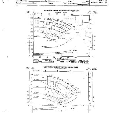
Worthington-d1000-pump-curves.pdf 4f586l
December 2021 0More Documents from "sebastian" o425n

Present Perfect Progressive 32325y
July 2021 0
Tipos De Prototipos 294i1n
November 2019 164
Worthington Instruction Book Pci07 En 4o496k
December 2019 77
Actividad De Estadistica 7 3t322q
July 2020 0
Derecho Sucesorio Tomo I 4z4wm
September 2020 0