Voith Torque Converter 6q6r37
This document was ed by and they confirmed that they have the permission to share it. If you are author or own the copyright of this book, please report to us by using this report form. Report r6l17
Overview 4q3b3c
& View Voith Torque Converter as PDF for free.
More details 26j3b
- Words: 6,169
- Pages: 22
Cr228e_Torque.qxd
12.08.2004
9:26 Uhr
Seite U1
Voith Turbo
Voith Torque Converter starting system for gas turbines
Cr228e_Torque.qxd
12.08.2004
9:26 Uhr
Seite 2
Voith – Our company
Voith is a reliable partner to essential industries. We set standards worldwide for paper making technology, power transmission, energy technology and for industrial services. With annual sales of approx.
€ 3.1 billion,
24,000 employees and 180 locations worldwide Voith is one of the large family-owned companies in Europe.
We want to be our customers’ preferred
The engine of our strong growth:
supplier and business partner
innovative power and reliability
Quality, reliability and soundness are key concepts of our identity.
Voith engineers have again and again written new chapters in the history of technology. Today, Voith holds over 7,000 active patents worldwide. Approximately 400 new ones are added every year.
These are expressed in three words: Voith – Engineered reliability.
The dynamic development and the growth over the last few years confirm that we have taken the right steps. We will continue to expand our worldwide dedication to our markets.
Cr228e_Torque.qxd
12.08.2004
9:26 Uhr
Seite 3
Reliability & Availability: Choosing the right system is important Gas turbines are often started several times a day. Choosing the right starting system will affect the start-up reliability of the gas turbine. Voith supplies torque converters to all leading gas turbine manufacturers and their licensees, to start gas turbines ranging in power from 20 to 270 MW.
The combination of an induction motor with a Voith torque converter is synonymous with trouble free start-ups, high reliability, and long service life. More than 3,500 gas turbine starters worldwide is outstanding evidence of our experience and know-how in this area.
We believe no other starting system or method equals the reliability and availability of the Voith torque converter starting system. Our exceptionally high MTBF (mean time between failure) leads to a statistical reliability of 99.97%. We also know of no other starting system
M
that matches the 35-year design life of the Voith torque converter; and this comes with a guaranteed availability of parts and service matching the life of our machines. The compact and rigid design offers trouble free operation while maintenance expenses are at a minimum.
TC
Starter System
Generator
Gas Turbine
2 3
Cr228e_Torque.qxd
12.08.2004
9:11 Uhr
Seite 4
Torque Converter benefits, function and design
Basic Design Hydrodynamic Torque Converter
The Benefits
Typical Gas Turbine Start-Up Curve MT MP η 1 2 3
Voith torque converters are designed and built to meet customer requirements. No other torque converter manufacturer offers this service.
Guide Vanes (adjustable)
Pump Wheel
MT MP η
Turbine Wheel
= = = = = =
Turbine torque Pump torque Efficiency Turbine wheel Pump wheel Mass flow (oil)
Typical gas turbine start-up curve Typical high speed setting Typical low speed setting
Torsional vibration dampening and shock free MT
power transmission; consequently, no stress η
applied to connected equipment thus delivering long service life.
Using a multi-position guide vane actuator, multiple hold points and acceleration speeds can easily be part of the control logic.
MP
“No-load starting” condition on the starting
1
motor by decoupling the motor from the load nT = 0
through the “working oil shut-off valve” feature.
nT = nTmax
1 Breakaway 2 Unfired resistance 3 Purge point (air exchange) 4 Firing speed 5 Acceleration resistance to selfsustained speed 6 Self-sustained speed
1 2 3 4
2
1 M
5
R
5 6 7 8 9 10 11
6
3
T
Low maintenance expenses.
Torque converter Torque converter housing Fill and drain valve Control valve (Filling and draining) Guide vane adjustment Orifice plate Working oil supply Lube oil and cooling oil supply Working oil return Lube oil and cooling oil return Lube oil tank of gas turbine
4
4
8
The Voith torque converter decouples the =n
nT
mechanical clutch through our exclusive “work-
ax Tm
M t n T = n op
3
ing oil shut-off valve” feature. Smooth and stepless output speed & torque
2
adjustment of the torque converter.
Because of the change in mass flow (due to the adjustable guide vanes) the turbine wheels’ speed is variable and can be adjusted to match the various operating points of the gas turbine. At low speed, the turbine develops its highest torque. With increasing turbine speed, output torque decreases.
Depending on the design of the turbine wheel the output torque at the break-away (nT = 0) point is two to ten times that of the pump (input) torque. The guide vanes absorb the torque differential between the turbine (output) and the pump (input) and transfer it to
2
nT = 0
7
9
10
M
5
11
Torque
1
gas turbine operation without the need for a
to the gas turbine/generator shaft. The adjustable vanes of the guide wheel regulate the mass flow in the circuit. At closed guide vanes (small mass flow) the power transmission is at its minimum. With the guide vanes completely open (large mass flow), the power transmission is at its maximum. Commonly, a constant speed driver such as an induction motor or a diesel engine drives the pump wheel (input shaft of the torque converter).
10
3
starting motor from the gas turbine train during
The heart of Voith’s hydrodynamic torque converter is its hydraulic circuit; consisting of a pump, turbine, and a guide wheel with adjustable guide vanes (see picture above right). This is combined in a common housing filled with hydraulic oil. The mechanical energy of the motor is converted into hydraulic energy through the pump wheel. In the turbine wheel the same hydraulic energy is converted back into mechanical energy and transmitted
Typical Starter System P&I Diagram
6 0% Speed
the foundation. By placing the guide vanes upstream of the pump wheel, the torque requirement of the pump (input) remains constant at a given guide vane setting, independent of the load on the turbine (output). That means an overload of the driver (motor or engine) is not possible
100%
through the hydraulic circuit. When the hydraulic fluid is removed from the torque converter circuit, the pump (input) is “uncoupled” from the turbine (output) and consequently, the starter motor or engine is disconnected from the gas turbine.
Through its characteristic of high torque at low output speed, the torque converter is the ideal gas turbine starter. With the abundant acceleration torque available, the gas turbine can be quickly accelerated to and above its self-sustained speed, an important requirement of the state-of-the-art, high temperature gas turbines.
4 5
Start Up
Other Functions
Break-away of the gas turbine through the torque converter or the integral turning gear Acceleration to purge speed Acceleration to firing speed Assisting the gas turbine to and above self sustained speed Uncoupling the starting system from the gas turbine
Turning the gas turbine by means of the integral turning gear for slow-roll functions Indexing the gas turbine for inspections Fast spin-cooling of the gas turbine for rapid maintenance availability Extended gas turbine waterwash cycles
6
12.08.2004
9:11 Uhr
Seite 7
Torque Converter power chart
Torque Converter Model EL..Y the classic design
Power Chart
Torque/Speed Characteristics 1
n P = constant 4.0
Torque converter for gas turbine starting
400
3.5
200 Torque converter in pump storage power plants
100
3.0
6
5
3
2 12
11
4
6
13
Simplified longitudinal section of Torque Converter
14
1.0
Lx = 100% Lx = 75% Lx = 50% Lx = 25% Lx = 0%
Type EL 10 YFG 6.5 0.5 MP
600
2.5 2.0 20 1.5
1 2 3 4 5 6 7 8 9 10 11 12 13 14
0 Lx = MP = MT = nP = nT =
40
Guide vanes open Input torque Output torque Input speed Output speed
10 1.0 4 MT/MP
Converter input power Pp [MW]
2
10
0.5
10 0 0.2 nT/nP
1
Input shaft Pump wheel Turbine wheel Output shaft Adjustable guide vanes Adjusting mechanism Filling and draining valve Working oil supply Working oil return Lube oil return Axial bearing Radial bearing Hydraulic cylinder Guide vane actuator
0 0.6
1.0
7
8
9
0.4 400 600
1000
2000
4000
6000 8000
Converter input speed nP [min-1]
Power versus input speed chart of exiting torque converters.
7
Selection of EL..Y
Type EL 6,8 YFG 1.5 / Type EL 7,5 YFG 2.2
Type EL 10 YFG 6.5
870
2,200
1,270
6,500
3,700
Input speed (min-1)
3,600
3,000
3,600
3,000
3,600
3,000 475
1,500
852
EL 10 YFG 6.5
ø110
EL 7,5 YFG 2.2
ø80
EL 6,8 YFG 1.5
1100
Starter Model Max. Input power (kW)
650
torque converter becomes a true variable speed drive with peak precision. The hydraulic fluid for the torque converter can be supplied by the gas turbine lube-oil system or through a complete packaged starter version including an oil reservoir system as available from Voith Turbo. Examples of other options for turning the gas turbine are: Installing a “pony” motor at the ODE of the starting motor or installing a separate turning gear.
ø160
The model EL..Y with its single stage turbine offers a torque multiplication factor of 4. Its balance of features and torque characteristics in combination with an integral turning gear makes it the ideal starter for a broad range of gas turbines. With the powerful hydraulic guide vane system, controlled by solenoid valves or an electric actuator, the various operating points of the gas turbine are easily obtained. When combining the actuator with a 4-20 mA system, the
ø100
Cr228e_Torque.qxd
323
360
690 1651
174 900
600 1164
720
8 9
Cr228e_Torque.qxd
12.08.2004
9:27 Uhr
Seite 10
Torque Converter Model EL..Z the mighty one
the torque converter can be supplied by the gas turbine lube-oil system or through a complete packaged starter version including an oil reservoir system as available from Voith Turbo. By activating a simple solenoid valve the torque converter operating fluid is emptied from the torque converter circuit and thus,
uncouples the starting system from the gas turbine. Turning can be done using an integral or separate turning gear or a pony motor.
Torque/Speed Characteristics n P = constant 10
1.0
9 Lx = 100% Lx = 75% Lx = 50% Lx = 25% Lx = 0%
7 6
0,5 MP
8
0 Lx = Guide vanes open MP = Input torque MT = Output torque nP = Input speed nT = Output speed
5 4 3 2 MT/MP
We call it the mighty one because, with its double stage turbine, it offers a torque multiplication factor of 10! It is used in applications with high break-away torque. For various operation points of the gas turbine, the guide vane adjustment is equipped, in this case, with an electric actuator. The hydraulic fluid for
1 0 0 nT/nP
0.2
0.4
0.6
0.8
9:27 Uhr
Seite 11
Selection of EL..Z Starter Model
Type EL 10 ZFG EL 10 ZFG 1092
1,800
Input speed (min-1)
3,000
555
ø82
Max. Input power (kW)
1485
12.08.2004
ø127
Cr228e_Torque.qxd
864
720 111,8
1
6
5
3
2
4
6
Simplified longitudinal section of Torque Converter Type EL 10 ZFG 1 2 3 4 5 6 7 8 9 10
Input shaft Pump wheel Turbine wheel Output shaft Adjustable guide vanes Adjusting mechanism Filling and draining valve Working oil supply Working oil return Lube and cooling oil return
10 7
8
9
10 11
Cr228e_Torque.qxd
12.08.2004
9:27 Uhr
Seite 12
Torque Converter Model EL.. where power meets speed
MT/MP
Torque/Speed Characteristics
2.00 1.75 1.50 1.25 1.00 0.75 0.50 0.25 0
Lx = 100% Lx = 75% Lx = 50% Lx = 25% Lx = 0%
MT
0.2 0 nT/nP
0.4
0.6
0.8
1.0
1.2
1.4
MP
MP 1.00 0.75 0.50 0.25 0 Lx = Guide vanes open MP = Input torque MT = Output torque
With its single stage turbine and its torque multiplication factor of approximately 2, the EL.. model offers over-synchronous output speed. With the powerful hydraulic guide vane system, controlled by solenoid valves or an electric actuator, the various operating points of the gas turbine are easily obtained. The robust, modular housing is designed for various torque converter sizes as well as other torque converter types.
The hydraulic fluid for the torque converter can be supplied by the gas turbine lube-oil system or through a complete packaged starter version including an oil reservoir system as available from Voith Turbo. Turning can be done using an integral or separate turning gear or a pony motor.
nP = Input speed nT = Output speed
Selection of EL.. Starter Model
EL 9 G 6.0
Max. Input power (kW)
6,000
3,400
Input speed (min-1)
3,600
3,000
Turning speed (min-1)
–
–
Breakaway Torque (Nm)
–
–
Cr228e_Torque.qxd
1
12.08.2004
6 5 3
9:27 Uhr
Seite 13
2
4
10
7
8
7
6
9
Simplified longitudinal section of Torque Converter Type EL 9 G 6.0 1 2 3 4 5 6 7 8 9 10 11 12
Input shaft Pump wheel Turbine wheel Output shaft Adjustable guide vanes Adjusting mechanism Hydraulic cylinder for guide vane adjusting Guide vane actuator Housing Fill and drain valve Operating oil supply Operating oil return
11
12
2.2
50,000
86,000
1945
3.0
650
3,600
ø180
3,600
ø119
7,500
650
6,000
ø119
EL 10 GTM 7.5-86
ø100
EL 9 GTM 6.0-50
Type EL 10 GTM 7.5-86
1895
Type EL 9 G 6.0
337
1006 1700
1260
357
540 880 2150
1260 1195
12 13
Cr228e_Torque.qxd
12.08.2004
9:27 Uhr
Seite 14
Torque Converter Model EL..YGTM with integral continuous turning gear
Like many of Voiths’ torque converters, this powerful unit is equipped with an integrated turning gear connected to the output shaft with an over-running clutch. Among the advantages of this design are space savings and reduced cost through the elimination of an additional coupling and subsequently, reduced assembly and alignment work. The turning gear is designed for long-life with emphasis on high
break-away torque and long periods of low-speed turning over the design life of 35 years. With this modular design, a large number of system combinations are available (different turning gear and torque converter sizes) permitting a high degree of customization. A large number of this model torque converter are in operation worldwide with integrated turning gears from 3,600 ft-lb (5000 Nm) to 80,000 ft-lb (110,000 Nm).
The turning gears are available with either AC or DC drive motors. In addition, an electro-pneumatic turning device is available for connection to the turning gear drive motor accessory shaft for ultra-slow indexing of the gas turbine. The same turning gears are also available as stand alone units.
Simplified longitudinal section of Torque Converter with integral turning gear Type EL 7,5 YGTM 2.2-86 1 2 3 4 5 6 7 8 9 10 11 12 13 14
Input shaft Output shaft Pump wheel Turbine wheel Adjustable guide vanes Housing Filling and draining valve Control valve for filling and draining Working oil supply Working oil return Overrunning clutch Worm gear Electric motor Bevel gear
9:27 Uhr
Seite 15
Selection of EL..YGTM EL 10,5 YGTM 10-110
Max. Input power (kW)
2,200
10,000
Input speed (min-1)
3,600
3,600
2.4
6.0
86,000
110,000
Breakaway Torque (Nm)
1
9
1187
475
Turning speed (min-1)
8
Type EL 7,5 YGTM 2.2-86
EL 7,5 YGTM 2.2-86
1064
Starter Model
ø180
12.08.2004
ø80
Cr228e_Torque.qxd
5
4
7 10
3
6
2
12 11
174
600
2
12 11
600 1726
720
13
14
14 15
Cr228e_Torque.qxd
12.08.2004
9:27 Uhr
Seite 16
Torque Converter EL..ZGTM with integral hydraulic turning device
Simplified longitudinal section of Torque Converter with integral turning device Type EL 7,5 ZGTM 1 2 3 4 5 6 7 8 9 10 11 12 13
This Voith torque converter with integrated hydraulic turning device is a well-proven design with hundreds of installations worldwide. Hydraulic cylinders produce the output torque, which is transmitted to the output shaft via an overrunning clutch. With each forward piston stroke, the gas turbine is turned 45 degrees.
Input shaft Output shaft Pump wheel Turbine wheel Adjustable guide vanes Housing Filling and draining valve Control valve for filling and draining Working oil supply Working oil return Overrunning clutch Return stroke piston/cylinder Working stroke piston/cylinder
With its double stage turbine the torque converter offers a torque multiplication factor of 10. For the various operating points of the gas turbine, the guide vane adjustment system is equipped, in this case, with an electric actuator with various limit and position switches.
12.08.2004
1
5
4
9
3 6
Seite 17
11
2
13
11
10 7
12
EL 7,5 ZGTM
EL 10 ZGTM-46
Max. Input power (kW)
1,000
1,800
Input speed (min-1)
3,600
3,000
45° intermittent
45° intermittent
35,000
46,000
Turning speed (min-1) Breakaway Torque (Nm)
475
Starter Model
Type EL 7,5 ZGTM
1009
Selection of EL..ZGTM
13
ø80
8
9:27 Uhr
ø119
Cr228e_Torque.qxd
108
600
251,5 1340
720
16 17
Cr228e_Torque.qxd
12.08.2004
9:27 Uhr
Seite 18
Torque Converter Type E.. with Fixed Guide Vanes the compact one
For gas turbines with a power of up to 45 MW, torque converters with fixed guide vanes are available and in operation in a large international fleet. The design is purposely built for high reliability and has a proven availability, superior to other types of starters. The output speed of this unit is controllable using a pressure reduction valve. Optionally, a hydraulic turning device can be integrated into this torque converter. Economical savings are achieved through the compact and simple design. With its integral gear step, this torque converter can be easily matched to any gas turbine speed requirements. For starters, where a diesel engine is used instead of an electric starting motor, the torque converter is ideally suited to the diesel motor characteristic and offers a no-load engine start.
Selection of E.. 5
Starter Model
4
Max. Input power (kW)
3 MT
2
E 5 WAT
E 6 WAT
E 6 YAT
E 7 WAT
E7W
E7Y
E8W
280/300
450
450
460/460
700
700
700
Input speed (min-1)
3,000/3,600
3,000
3,600
2,300/2,100
3,000
3,600
2,100
Turning speed (min-1)
45° intermittent
45° intermittent
45° intermittent
45° intermittent
–
–
–
11,000
11,000
11,000
11,000
–
–
–
MP M
1 0 0
0.2
0.4
0.6
0.8
n T/n P n P = constant
MP = Input torque MT = Output torque
1.0
1.2
Breakaway Torque (Nm)
Cr228e_Torque.qxd
12.08.2004
9:27 Uhr
Seite 19
P&I Diagram of Type E 7 WAT 1
4 2
3
5 6
7
Simplified longitudinal section of Torque converter
5
Type E 7 WAT nP
nT R
6
1 Input shaft with connecting coupling 2 Pump wheel 3 Turbine wheel 4 Fixed guide vanes 5 Gear stage 6 Output shaft 7 Hydrostatic turning device 8 Working oil supply 9 Working oil return
1 4 na
3
2
1 2 3 4 5
Torque converter Oil pump Relief valve Helical gear stage Hydrostatic turning device 6 Overrunning clutch 8
Type E 6 WAT
9
Type E 7 W without turning device ø78.3
614.1
50.8
ø 78.3 ø 620
ø 466.8
ø 511.18
ø447,7 ø352.48
305
342.9
633
74
628.2
870
18 19
Cr228e_Torque.qxd
12.08.2004
9:27 Uhr
Seite 20
Packaged Starter a complete-system solution
Schematic diagram for oil circuit of El 9 G 6.0 Package 1 2 3 4 5 6 7 8 9 10 11 12 13
Torque converter Torque converter housing Starting motor Control valve for guide vane position Guide vane actuator Transducer Filter for control oil Filling and draining valve Thermocouples Cooling oil Indicator for guide vane position Working oil pump Pressure gauge lube oil pressure
Voith engineers configure gas turbine starting packages specifically for your gas turbines. The table shows examples of starters in worldwide operation. The Voith engineers are eager to design and offer a system for your requirements.
Gas Turbine Starters GT Starter EL 6,8 YFG Modell
EL 6,8 YFG
EL 7,5 ZGTM EL 7,5 YGTM EL 7,5 YGTM EL 7,5 YGTM EL 10 YGTM 2.2-86 2.2-36 2.2-46 6.5-110
EL 9 G 6.0
EL 9 G 6.0
EL 9 GTM 6.0-50
Cranking
1,076 hp
1,005 hp
1,200 hp
2,500 hp
2,146 hp
2,500hp
5,000 hp
3,755 hp
4,025 hp
4,025 hp
Power
800 kW
750 kW
896 kW
1,865 kW
1,600 kW
1,865 kW
3,700 kW
2,800 kW
3,000 kW
3,000 kW
Speed
3,600 rpm
3,000 rpm
3,600 rpm
3,600 rpm
3,600 rpm
3,600 rpm
3,000 rpm
3,000 rpm
3,600 rpm
3,600 rpm
Turning Speed
–
–
45° Intermittent
2.4 rpm
2.3 rpm
2.3 rpm
3.0 rpm
–
–
3.0 rpm
Breakway Torque
– –
– –
35,000 Nm 86,000 Nm 36,000 Nm 46,000 Nm 110,000 Nm 25,800 ft-lbs 63,400 ft-lbs 26,500 ft-lbs 33,900 ft-lbs 81,100 ft-lbs
– –
– –
50,000 Nm 36,800 ft-lbs
Cr228e_Torque.qxd
12.08.2004
9:27 Uhr
Seite 21
Torque converter, motor, and all required accessory equipment are factory mounted on a common base. For more demanding requirements such as retro-fitting to older gas turbines, the design can include an integral oil tank for a self contained, packaged starter. An optionally available, onboard PLC system controls the various phases of the starting sequence. With this allinclusive solution, site assembly, alignment, and commissioning time is greatly reduced. The components of the packaged starting system are selected to compliment each other, achieving an economical and space conscious design. Due to the torque converter characteristic, the driver can be designed as a true starting motor. This means the driver (motor) can be used above its continuous rating during the short start-up of the gas turbine. This results in a smaller, space saving, and economical motor.
13
2 10 12
3 1
9
8 4 11
6
7 5
Type EL 9 G 6.0
12,874 hp
7,500 kW
9,600 kW
3,600 rpm
3,600 rpm
2.2 rpm
6.0 rpm
86,000 Nm 63,400 ft-lbs
110,000 Nm 81,100 ft-lbs
1700
1876
10,060 hp
2530
1651
EL 10,5 YGTM 10-110
2986
EL 10 GTM 7.5-86
3505
366 6180
20 21
Cr228e_Torque.qxd
12.08.2004
9:26 Uhr
Seite U4
Voith Turbo GmbH & Co. KG Variable Speed Drive P.O. Box 1555 74555 Crailsheim/ Tel. +49-7951-32-0 Fax +49-7951-32-650 [email protected] www.voith-variable-speed.com www.voithturbo.com
Cr 228 e 08.2004 2000 MSW/WA Printed in . Technical data and illustrations subject to change.
Voith Transmissions, Inc. 25 Winship Road, York PA 17402, USA Tel. +717-767-3200 Fax +717-767-3210 [email protected] www.usa.voithturbo.com
12.08.2004
9:26 Uhr
Seite U1
Voith Turbo
Voith Torque Converter starting system for gas turbines
Cr228e_Torque.qxd
12.08.2004
9:26 Uhr
Seite 2
Voith – Our company
Voith is a reliable partner to essential industries. We set standards worldwide for paper making technology, power transmission, energy technology and for industrial services. With annual sales of approx.
€ 3.1 billion,
24,000 employees and 180 locations worldwide Voith is one of the large family-owned companies in Europe.
We want to be our customers’ preferred
The engine of our strong growth:
supplier and business partner
innovative power and reliability
Quality, reliability and soundness are key concepts of our identity.
Voith engineers have again and again written new chapters in the history of technology. Today, Voith holds over 7,000 active patents worldwide. Approximately 400 new ones are added every year.
These are expressed in three words: Voith – Engineered reliability.
The dynamic development and the growth over the last few years confirm that we have taken the right steps. We will continue to expand our worldwide dedication to our markets.
Cr228e_Torque.qxd
12.08.2004
9:26 Uhr
Seite 3
Reliability & Availability: Choosing the right system is important Gas turbines are often started several times a day. Choosing the right starting system will affect the start-up reliability of the gas turbine. Voith supplies torque converters to all leading gas turbine manufacturers and their licensees, to start gas turbines ranging in power from 20 to 270 MW.
The combination of an induction motor with a Voith torque converter is synonymous with trouble free start-ups, high reliability, and long service life. More than 3,500 gas turbine starters worldwide is outstanding evidence of our experience and know-how in this area.
We believe no other starting system or method equals the reliability and availability of the Voith torque converter starting system. Our exceptionally high MTBF (mean time between failure) leads to a statistical reliability of 99.97%. We also know of no other starting system
M
that matches the 35-year design life of the Voith torque converter; and this comes with a guaranteed availability of parts and service matching the life of our machines. The compact and rigid design offers trouble free operation while maintenance expenses are at a minimum.
TC
Starter System
Generator
Gas Turbine
2 3
Cr228e_Torque.qxd
12.08.2004
9:11 Uhr
Seite 4
Torque Converter benefits, function and design
Basic Design Hydrodynamic Torque Converter
The Benefits
Typical Gas Turbine Start-Up Curve MT MP η 1 2 3
Voith torque converters are designed and built to meet customer requirements. No other torque converter manufacturer offers this service.
Guide Vanes (adjustable)
Pump Wheel
MT MP η
Turbine Wheel
= = = = = =
Turbine torque Pump torque Efficiency Turbine wheel Pump wheel Mass flow (oil)
Typical gas turbine start-up curve Typical high speed setting Typical low speed setting
Torsional vibration dampening and shock free MT
power transmission; consequently, no stress η
applied to connected equipment thus delivering long service life.
Using a multi-position guide vane actuator, multiple hold points and acceleration speeds can easily be part of the control logic.
MP
“No-load starting” condition on the starting
1
motor by decoupling the motor from the load nT = 0
through the “working oil shut-off valve” feature.
nT = nTmax
1 Breakaway 2 Unfired resistance 3 Purge point (air exchange) 4 Firing speed 5 Acceleration resistance to selfsustained speed 6 Self-sustained speed
1 2 3 4
2
1 M
5
R
5 6 7 8 9 10 11
6
3
T
Low maintenance expenses.
Torque converter Torque converter housing Fill and drain valve Control valve (Filling and draining) Guide vane adjustment Orifice plate Working oil supply Lube oil and cooling oil supply Working oil return Lube oil and cooling oil return Lube oil tank of gas turbine
4
4
8
The Voith torque converter decouples the =n
nT
mechanical clutch through our exclusive “work-
ax Tm
M t n T = n op
3
ing oil shut-off valve” feature. Smooth and stepless output speed & torque
2
adjustment of the torque converter.
Because of the change in mass flow (due to the adjustable guide vanes) the turbine wheels’ speed is variable and can be adjusted to match the various operating points of the gas turbine. At low speed, the turbine develops its highest torque. With increasing turbine speed, output torque decreases.
Depending on the design of the turbine wheel the output torque at the break-away (nT = 0) point is two to ten times that of the pump (input) torque. The guide vanes absorb the torque differential between the turbine (output) and the pump (input) and transfer it to
2
nT = 0
7
9
10
M
5
11
Torque
1
gas turbine operation without the need for a
to the gas turbine/generator shaft. The adjustable vanes of the guide wheel regulate the mass flow in the circuit. At closed guide vanes (small mass flow) the power transmission is at its minimum. With the guide vanes completely open (large mass flow), the power transmission is at its maximum. Commonly, a constant speed driver such as an induction motor or a diesel engine drives the pump wheel (input shaft of the torque converter).
10
3
starting motor from the gas turbine train during
The heart of Voith’s hydrodynamic torque converter is its hydraulic circuit; consisting of a pump, turbine, and a guide wheel with adjustable guide vanes (see picture above right). This is combined in a common housing filled with hydraulic oil. The mechanical energy of the motor is converted into hydraulic energy through the pump wheel. In the turbine wheel the same hydraulic energy is converted back into mechanical energy and transmitted
Typical Starter System P&I Diagram
6 0% Speed
the foundation. By placing the guide vanes upstream of the pump wheel, the torque requirement of the pump (input) remains constant at a given guide vane setting, independent of the load on the turbine (output). That means an overload of the driver (motor or engine) is not possible
100%
through the hydraulic circuit. When the hydraulic fluid is removed from the torque converter circuit, the pump (input) is “uncoupled” from the turbine (output) and consequently, the starter motor or engine is disconnected from the gas turbine.
Through its characteristic of high torque at low output speed, the torque converter is the ideal gas turbine starter. With the abundant acceleration torque available, the gas turbine can be quickly accelerated to and above its self-sustained speed, an important requirement of the state-of-the-art, high temperature gas turbines.
4 5
Start Up
Other Functions
Break-away of the gas turbine through the torque converter or the integral turning gear Acceleration to purge speed Acceleration to firing speed Assisting the gas turbine to and above self sustained speed Uncoupling the starting system from the gas turbine
Turning the gas turbine by means of the integral turning gear for slow-roll functions Indexing the gas turbine for inspections Fast spin-cooling of the gas turbine for rapid maintenance availability Extended gas turbine waterwash cycles
6
Cr228e_Torque.qxd
12.08.2004
9:11 Uhr
Seite 4
Torque Converter benefits, function and design
Basic Design Hydrodynamic Torque Converter
The Benefits
Typical Gas Turbine Start-Up Curve MT MP η 1 2 3
Voith torque converters are designed and built to meet customer requirements. No other torque converter manufacturer offers this service.
Guide Vanes (adjustable)
Pump Wheel
MT MP η
Turbine Wheel
= = = = = =
Turbine torque Pump torque Efficiency Turbine wheel Pump wheel Mass flow (oil)
Typical gas turbine start-up curve Typical high speed setting Typical low speed setting
Torsional vibration dampening and shock free MT
power transmission; consequently, no stress η
applied to connected equipment thus delivering long service life.
Using a multi-position guide vane actuator, multiple hold points and acceleration speeds can easily be part of the control logic.
MP
“No-load starting” condition on the starting
1
motor by decoupling the motor from the load nT = 0
through the “working oil shut-off valve” feature.
nT = nTmax
1 Breakaway 2 Unfired resistance 3 Purge point (air exchange) 4 Firing speed 5 Acceleration resistance to selfsustained speed 6 Self-sustained speed
1 2 3 4
2
1 M
5
R
5 6 7 8 9 10 11
6
3
T
Low maintenance expenses.
Torque converter Torque converter housing Fill and drain valve Control valve (Filling and draining) Guide vane adjustment Orifice plate Working oil supply Lube oil and cooling oil supply Working oil return Lube oil and cooling oil return Lube oil tank of gas turbine
4
4
8
The Voith torque converter decouples the =n
nT
mechanical clutch through our exclusive “work-
ax Tm
M t n T = n op
3
ing oil shut-off valve” feature. Smooth and stepless output speed & torque
2
adjustment of the torque converter.
Because of the change in mass flow (due to the adjustable guide vanes) the turbine wheels’ speed is variable and can be adjusted to match the various operating points of the gas turbine. At low speed, the turbine develops its highest torque. With increasing turbine speed, output torque decreases.
Depending on the design of the turbine wheel the output torque at the break-away (nT = 0) point is two to ten times that of the pump (input) torque. The guide vanes absorb the torque differential between the turbine (output) and the pump (input) and transfer it to
2
nT = 0
7
9
10
M
5
11
Torque
1
gas turbine operation without the need for a
to the gas turbine/generator shaft. The adjustable vanes of the guide wheel regulate the mass flow in the circuit. At closed guide vanes (small mass flow) the power transmission is at its minimum. With the guide vanes completely open (large mass flow), the power transmission is at its maximum. Commonly, a constant speed driver such as an induction motor or a diesel engine drives the pump wheel (input shaft of the torque converter).
10
3
starting motor from the gas turbine train during
The heart of Voith’s hydrodynamic torque converter is its hydraulic circuit; consisting of a pump, turbine, and a guide wheel with adjustable guide vanes (see picture above right). This is combined in a common housing filled with hydraulic oil. The mechanical energy of the motor is converted into hydraulic energy through the pump wheel. In the turbine wheel the same hydraulic energy is converted back into mechanical energy and transmitted
Typical Starter System P&I Diagram
6 0% Speed
the foundation. By placing the guide vanes upstream of the pump wheel, the torque requirement of the pump (input) remains constant at a given guide vane setting, independent of the load on the turbine (output). That means an overload of the driver (motor or engine) is not possible
100%
through the hydraulic circuit. When the hydraulic fluid is removed from the torque converter circuit, the pump (input) is “uncoupled” from the turbine (output) and consequently, the starter motor or engine is disconnected from the gas turbine.
Through its characteristic of high torque at low output speed, the torque converter is the ideal gas turbine starter. With the abundant acceleration torque available, the gas turbine can be quickly accelerated to and above its self-sustained speed, an important requirement of the state-of-the-art, high temperature gas turbines.
4 5
Start Up
Other Functions
Break-away of the gas turbine through the torque converter or the integral turning gear Acceleration to purge speed Acceleration to firing speed Assisting the gas turbine to and above self sustained speed Uncoupling the starting system from the gas turbine
Turning the gas turbine by means of the integral turning gear for slow-roll functions Indexing the gas turbine for inspections Fast spin-cooling of the gas turbine for rapid maintenance availability Extended gas turbine waterwash cycles
6
Cr228e_Torque.qxd
12.08.2004
9:11 Uhr
Seite 4
Torque Converter benefits, function and design
Basic Design Hydrodynamic Torque Converter
The Benefits
Typical Gas Turbine Start-Up Curve MT MP η 1 2 3
Voith torque converters are designed and built to meet customer requirements. No other torque converter manufacturer offers this service.
Guide Vanes (adjustable)
Pump Wheel
MT MP η
Turbine Wheel
= = = = = =
Turbine torque Pump torque Efficiency Turbine wheel Pump wheel Mass flow (oil)
Typical gas turbine start-up curve Typical high speed setting Typical low speed setting
Torsional vibration dampening and shock free MT
power transmission; consequently, no stress η
applied to connected equipment thus delivering long service life.
Using a multi-position guide vane actuator, multiple hold points and acceleration speeds can easily be part of the control logic.
MP
“No-load starting” condition on the starting
1
motor by decoupling the motor from the load nT = 0
through the “working oil shut-off valve” feature.
nT = nTmax
1 Breakaway 2 Unfired resistance 3 Purge point (air exchange) 4 Firing speed 5 Acceleration resistance to selfsustained speed 6 Self-sustained speed
1 2 3 4
2
1 M
5
R
5 6 7 8 9 10 11
6
3
T
Low maintenance expenses.
Torque converter Torque converter housing Fill and drain valve Control valve (Filling and draining) Guide vane adjustment Orifice plate Working oil supply Lube oil and cooling oil supply Working oil return Lube oil and cooling oil return Lube oil tank of gas turbine
4
4
8
The Voith torque converter decouples the =n
nT
mechanical clutch through our exclusive “work-
ax Tm
M t n T = n op
3
ing oil shut-off valve” feature. Smooth and stepless output speed & torque
2
adjustment of the torque converter.
Because of the change in mass flow (due to the adjustable guide vanes) the turbine wheels’ speed is variable and can be adjusted to match the various operating points of the gas turbine. At low speed, the turbine develops its highest torque. With increasing turbine speed, output torque decreases.
Depending on the design of the turbine wheel the output torque at the break-away (nT = 0) point is two to ten times that of the pump (input) torque. The guide vanes absorb the torque differential between the turbine (output) and the pump (input) and transfer it to
2
nT = 0
7
9
10
M
5
11
Torque
1
gas turbine operation without the need for a
to the gas turbine/generator shaft. The adjustable vanes of the guide wheel regulate the mass flow in the circuit. At closed guide vanes (small mass flow) the power transmission is at its minimum. With the guide vanes completely open (large mass flow), the power transmission is at its maximum. Commonly, a constant speed driver such as an induction motor or a diesel engine drives the pump wheel (input shaft of the torque converter).
10
3
starting motor from the gas turbine train during
The heart of Voith’s hydrodynamic torque converter is its hydraulic circuit; consisting of a pump, turbine, and a guide wheel with adjustable guide vanes (see picture above right). This is combined in a common housing filled with hydraulic oil. The mechanical energy of the motor is converted into hydraulic energy through the pump wheel. In the turbine wheel the same hydraulic energy is converted back into mechanical energy and transmitted
Typical Starter System P&I Diagram
6 0% Speed
the foundation. By placing the guide vanes upstream of the pump wheel, the torque requirement of the pump (input) remains constant at a given guide vane setting, independent of the load on the turbine (output). That means an overload of the driver (motor or engine) is not possible
100%
through the hydraulic circuit. When the hydraulic fluid is removed from the torque converter circuit, the pump (input) is “uncoupled” from the turbine (output) and consequently, the starter motor or engine is disconnected from the gas turbine.
Through its characteristic of high torque at low output speed, the torque converter is the ideal gas turbine starter. With the abundant acceleration torque available, the gas turbine can be quickly accelerated to and above its self-sustained speed, an important requirement of the state-of-the-art, high temperature gas turbines.
4 5
Start Up
Other Functions
Break-away of the gas turbine through the torque converter or the integral turning gear Acceleration to purge speed Acceleration to firing speed Assisting the gas turbine to and above self sustained speed Uncoupling the starting system from the gas turbine
Turning the gas turbine by means of the integral turning gear for slow-roll functions Indexing the gas turbine for inspections Fast spin-cooling of the gas turbine for rapid maintenance availability Extended gas turbine waterwash cycles
6
12.08.2004
9:11 Uhr
Seite 7
Torque Converter power chart
Torque Converter Model EL..Y the classic design
Power Chart
Torque/Speed Characteristics 1
n P = constant 4.0
Torque converter for gas turbine starting
400
3.5
200 Torque converter in pump storage power plants
100
3.0
6
5
3
2 12
11
4
6
13
Simplified longitudinal section of Torque Converter
14
1.0
Lx = 100% Lx = 75% Lx = 50% Lx = 25% Lx = 0%
Type EL 10 YFG 6.5 0.5 MP
600
2.5 2.0 20 1.5
1 2 3 4 5 6 7 8 9 10 11 12 13 14
0 Lx = MP = MT = nP = nT =
40
Guide vanes open Input torque Output torque Input speed Output speed
10 1.0 4 MT/MP
Converter input power Pp [MW]
2
10
0.5
10 0 0.2 nT/nP
1
Input shaft Pump wheel Turbine wheel Output shaft Adjustable guide vanes Adjusting mechanism Filling and draining valve Working oil supply Working oil return Lube oil return Axial bearing Radial bearing Hydraulic cylinder Guide vane actuator
0 0.6
1.0
7
8
9
0.4 400 600
1000
2000
4000
6000 8000
Converter input speed nP [min-1]
Power versus input speed chart of exiting torque converters.
7
Selection of EL..Y
Type EL 6,8 YFG 1.5 / Type EL 7,5 YFG 2.2
Type EL 10 YFG 6.5
870
2,200
1,270
6,500
3,700
Input speed (min-1)
3,600
3,000
3,600
3,000
3,600
3,000 475
1,500
852
EL 10 YFG 6.5
ø110
EL 7,5 YFG 2.2
ø80
EL 6,8 YFG 1.5
1100
Starter Model Max. Input power (kW)
650
torque converter becomes a true variable speed drive with peak precision. The hydraulic fluid for the torque converter can be supplied by the gas turbine lube-oil system or through a complete packaged starter version including an oil reservoir system as available from Voith Turbo. Examples of other options for turning the gas turbine are: Installing a “pony” motor at the ODE of the starting motor or installing a separate turning gear.
ø160
The model EL..Y with its single stage turbine offers a torque multiplication factor of 4. Its balance of features and torque characteristics in combination with an integral turning gear makes it the ideal starter for a broad range of gas turbines. With the powerful hydraulic guide vane system, controlled by solenoid valves or an electric actuator, the various operating points of the gas turbine are easily obtained. When combining the actuator with a 4-20 mA system, the
ø100
Cr228e_Torque.qxd
323
360
690 1651
174 900
600 1164
720
8 9
12.08.2004
9:11 Uhr
Seite 7
Torque Converter power chart
Torque Converter Model EL..Y the classic design
Power Chart
Torque/Speed Characteristics 1
n P = constant 4.0
Torque converter for gas turbine starting
400
3.5
200 Torque converter in pump storage power plants
100
3.0
6
5
3
2 12
11
4
6
13
Simplified longitudinal section of Torque Converter
14
1.0
Lx = 100% Lx = 75% Lx = 50% Lx = 25% Lx = 0%
Type EL 10 YFG 6.5 0.5 MP
600
2.5 2.0 20 1.5
1 2 3 4 5 6 7 8 9 10 11 12 13 14
0 Lx = MP = MT = nP = nT =
40
Guide vanes open Input torque Output torque Input speed Output speed
10 1.0 4 MT/MP
Converter input power Pp [MW]
2
10
0.5
10 0 0.2 nT/nP
1
Input shaft Pump wheel Turbine wheel Output shaft Adjustable guide vanes Adjusting mechanism Filling and draining valve Working oil supply Working oil return Lube oil return Axial bearing Radial bearing Hydraulic cylinder Guide vane actuator
0 0.6
1.0
7
8
9
0.4 400 600
1000
2000
4000
6000 8000
Converter input speed nP [min-1]
Power versus input speed chart of exiting torque converters.
7
Selection of EL..Y
Type EL 6,8 YFG 1.5 / Type EL 7,5 YFG 2.2
Type EL 10 YFG 6.5
870
2,200
1,270
6,500
3,700
Input speed (min-1)
3,600
3,000
3,600
3,000
3,600
3,000 475
1,500
852
EL 10 YFG 6.5
ø110
EL 7,5 YFG 2.2
ø80
EL 6,8 YFG 1.5
1100
Starter Model Max. Input power (kW)
650
torque converter becomes a true variable speed drive with peak precision. The hydraulic fluid for the torque converter can be supplied by the gas turbine lube-oil system or through a complete packaged starter version including an oil reservoir system as available from Voith Turbo. Examples of other options for turning the gas turbine are: Installing a “pony” motor at the ODE of the starting motor or installing a separate turning gear.
ø160
The model EL..Y with its single stage turbine offers a torque multiplication factor of 4. Its balance of features and torque characteristics in combination with an integral turning gear makes it the ideal starter for a broad range of gas turbines. With the powerful hydraulic guide vane system, controlled by solenoid valves or an electric actuator, the various operating points of the gas turbine are easily obtained. When combining the actuator with a 4-20 mA system, the
ø100
Cr228e_Torque.qxd
323
360
690 1651
174 900
600 1164
720
8 9
12.08.2004
9:11 Uhr
Seite 7
Torque Converter power chart
Torque Converter Model EL..Y the classic design
Power Chart
Torque/Speed Characteristics 1
n P = constant 4.0
Torque converter for gas turbine starting
400
3.5
200 Torque converter in pump storage power plants
100
3.0
6
5
3
2 12
11
4
6
13
Simplified longitudinal section of Torque Converter
14
1.0
Lx = 100% Lx = 75% Lx = 50% Lx = 25% Lx = 0%
Type EL 10 YFG 6.5 0.5 MP
600
2.5 2.0 20 1.5
1 2 3 4 5 6 7 8 9 10 11 12 13 14
0 Lx = MP = MT = nP = nT =
40
Guide vanes open Input torque Output torque Input speed Output speed
10 1.0 4 MT/MP
Converter input power Pp [MW]
2
10
0.5
10 0 0.2 nT/nP
1
Input shaft Pump wheel Turbine wheel Output shaft Adjustable guide vanes Adjusting mechanism Filling and draining valve Working oil supply Working oil return Lube oil return Axial bearing Radial bearing Hydraulic cylinder Guide vane actuator
0 0.6
1.0
7
8
9
0.4 400 600
1000
2000
4000
6000 8000
Converter input speed nP [min-1]
Power versus input speed chart of exiting torque converters.
7
Selection of EL..Y
Type EL 6,8 YFG 1.5 / Type EL 7,5 YFG 2.2
Type EL 10 YFG 6.5
870
2,200
1,270
6,500
3,700
Input speed (min-1)
3,600
3,000
3,600
3,000
3,600
3,000 475
1,500
852
EL 10 YFG 6.5
ø110
EL 7,5 YFG 2.2
ø80
EL 6,8 YFG 1.5
1100
Starter Model Max. Input power (kW)
650
torque converter becomes a true variable speed drive with peak precision. The hydraulic fluid for the torque converter can be supplied by the gas turbine lube-oil system or through a complete packaged starter version including an oil reservoir system as available from Voith Turbo. Examples of other options for turning the gas turbine are: Installing a “pony” motor at the ODE of the starting motor or installing a separate turning gear.
ø160
The model EL..Y with its single stage turbine offers a torque multiplication factor of 4. Its balance of features and torque characteristics in combination with an integral turning gear makes it the ideal starter for a broad range of gas turbines. With the powerful hydraulic guide vane system, controlled by solenoid valves or an electric actuator, the various operating points of the gas turbine are easily obtained. When combining the actuator with a 4-20 mA system, the
ø100
Cr228e_Torque.qxd
323
360
690 1651
174 900
600 1164
720
8 9
Cr228e_Torque.qxd
12.08.2004
9:27 Uhr
Seite 10
Torque Converter Model EL..Z the mighty one
the torque converter can be supplied by the gas turbine lube-oil system or through a complete packaged starter version including an oil reservoir system as available from Voith Turbo. By activating a simple solenoid valve the torque converter operating fluid is emptied from the torque converter circuit and thus,
uncouples the starting system from the gas turbine. Turning can be done using an integral or separate turning gear or a pony motor.
Torque/Speed Characteristics n P = constant 10
1.0
9 Lx = 100% Lx = 75% Lx = 50% Lx = 25% Lx = 0%
7 6
0,5 MP
8
0 Lx = Guide vanes open MP = Input torque MT = Output torque nP = Input speed nT = Output speed
5 4 3 2 MT/MP
We call it the mighty one because, with its double stage turbine, it offers a torque multiplication factor of 10! It is used in applications with high break-away torque. For various operation points of the gas turbine, the guide vane adjustment is equipped, in this case, with an electric actuator. The hydraulic fluid for
1 0 0 nT/nP
0.2
0.4
0.6
0.8
9:27 Uhr
Seite 11
Selection of EL..Z Starter Model
Type EL 10 ZFG EL 10 ZFG 1092
1,800
Input speed (min-1)
3,000
555
ø82
Max. Input power (kW)
1485
12.08.2004
ø127
Cr228e_Torque.qxd
864
720 111,8
1
6
5
3
2
4
6
Simplified longitudinal section of Torque Converter Type EL 10 ZFG 1 2 3 4 5 6 7 8 9 10
Input shaft Pump wheel Turbine wheel Output shaft Adjustable guide vanes Adjusting mechanism Filling and draining valve Working oil supply Working oil return Lube and cooling oil return
10 7
8
9
10 11
Cr228e_Torque.qxd
12.08.2004
9:27 Uhr
Seite 12
Torque Converter Model EL.. where power meets speed
MT/MP
Torque/Speed Characteristics
2.00 1.75 1.50 1.25 1.00 0.75 0.50 0.25 0
Lx = 100% Lx = 75% Lx = 50% Lx = 25% Lx = 0%
MT
0.2 0 nT/nP
0.4
0.6
0.8
1.0
1.2
1.4
MP
MP 1.00 0.75 0.50 0.25 0 Lx = Guide vanes open MP = Input torque MT = Output torque
With its single stage turbine and its torque multiplication factor of approximately 2, the EL.. model offers over-synchronous output speed. With the powerful hydraulic guide vane system, controlled by solenoid valves or an electric actuator, the various operating points of the gas turbine are easily obtained. The robust, modular housing is designed for various torque converter sizes as well as other torque converter types.
The hydraulic fluid for the torque converter can be supplied by the gas turbine lube-oil system or through a complete packaged starter version including an oil reservoir system as available from Voith Turbo. Turning can be done using an integral or separate turning gear or a pony motor.
nP = Input speed nT = Output speed
Selection of EL.. Starter Model
EL 9 G 6.0
Max. Input power (kW)
6,000
3,400
Input speed (min-1)
3,600
3,000
Turning speed (min-1)
–
–
Breakaway Torque (Nm)
–
–
Cr228e_Torque.qxd
1
12.08.2004
6 5 3
9:27 Uhr
Seite 13
2
4
10
7
8
7
6
9
Simplified longitudinal section of Torque Converter Type EL 9 G 6.0 1 2 3 4 5 6 7 8 9 10 11 12
Input shaft Pump wheel Turbine wheel Output shaft Adjustable guide vanes Adjusting mechanism Hydraulic cylinder for guide vane adjusting Guide vane actuator Housing Fill and drain valve Operating oil supply Operating oil return
11
12
2.2
50,000
86,000
1945
3.0
650
3,600
ø180
3,600
ø119
7,500
650
6,000
ø119
EL 10 GTM 7.5-86
ø100
EL 9 GTM 6.0-50
Type EL 10 GTM 7.5-86
1895
Type EL 9 G 6.0
337
1006 1700
1260
357
540 880 2150
1260 1195
12 13
Cr228e_Torque.qxd
12.08.2004
9:27 Uhr
Seite 14
Torque Converter Model EL..YGTM with integral continuous turning gear
Like many of Voiths’ torque converters, this powerful unit is equipped with an integrated turning gear connected to the output shaft with an over-running clutch. Among the advantages of this design are space savings and reduced cost through the elimination of an additional coupling and subsequently, reduced assembly and alignment work. The turning gear is designed for long-life with emphasis on high
break-away torque and long periods of low-speed turning over the design life of 35 years. With this modular design, a large number of system combinations are available (different turning gear and torque converter sizes) permitting a high degree of customization. A large number of this model torque converter are in operation worldwide with integrated turning gears from 3,600 ft-lb (5000 Nm) to 80,000 ft-lb (110,000 Nm).
The turning gears are available with either AC or DC drive motors. In addition, an electro-pneumatic turning device is available for connection to the turning gear drive motor accessory shaft for ultra-slow indexing of the gas turbine. The same turning gears are also available as stand alone units.
Simplified longitudinal section of Torque Converter with integral turning gear Type EL 7,5 YGTM 2.2-86 1 2 3 4 5 6 7 8 9 10 11 12 13 14
Input shaft Output shaft Pump wheel Turbine wheel Adjustable guide vanes Housing Filling and draining valve Control valve for filling and draining Working oil supply Working oil return Overrunning clutch Worm gear Electric motor Bevel gear
9:27 Uhr
Seite 15
Selection of EL..YGTM EL 10,5 YGTM 10-110
Max. Input power (kW)
2,200
10,000
Input speed (min-1)
3,600
3,600
2.4
6.0
86,000
110,000
Breakaway Torque (Nm)
1
9
1187
475
Turning speed (min-1)
8
Type EL 7,5 YGTM 2.2-86
EL 7,5 YGTM 2.2-86
1064
Starter Model
ø180
12.08.2004
ø80
Cr228e_Torque.qxd
5
4
7 10
3
6
2
12 11
174
600
2
12 11
600 1726
720
13
14
14 15
Cr228e_Torque.qxd
12.08.2004
9:27 Uhr
Seite 16
Torque Converter EL..ZGTM with integral hydraulic turning device
Simplified longitudinal section of Torque Converter with integral turning device Type EL 7,5 ZGTM 1 2 3 4 5 6 7 8 9 10 11 12 13
This Voith torque converter with integrated hydraulic turning device is a well-proven design with hundreds of installations worldwide. Hydraulic cylinders produce the output torque, which is transmitted to the output shaft via an overrunning clutch. With each forward piston stroke, the gas turbine is turned 45 degrees.
Input shaft Output shaft Pump wheel Turbine wheel Adjustable guide vanes Housing Filling and draining valve Control valve for filling and draining Working oil supply Working oil return Overrunning clutch Return stroke piston/cylinder Working stroke piston/cylinder
With its double stage turbine the torque converter offers a torque multiplication factor of 10. For the various operating points of the gas turbine, the guide vane adjustment system is equipped, in this case, with an electric actuator with various limit and position switches.
12.08.2004
1
5
4
9
3 6
Seite 17
11
2
13
11
10 7
12
EL 7,5 ZGTM
EL 10 ZGTM-46
Max. Input power (kW)
1,000
1,800
Input speed (min-1)
3,600
3,000
45° intermittent
45° intermittent
35,000
46,000
Turning speed (min-1) Breakaway Torque (Nm)
475
Starter Model
Type EL 7,5 ZGTM
1009
Selection of EL..ZGTM
13
ø80
8
9:27 Uhr
ø119
Cr228e_Torque.qxd
108
600
251,5 1340
720
16 17
Cr228e_Torque.qxd
12.08.2004
9:27 Uhr
Seite 18
Torque Converter Type E.. with Fixed Guide Vanes the compact one
For gas turbines with a power of up to 45 MW, torque converters with fixed guide vanes are available and in operation in a large international fleet. The design is purposely built for high reliability and has a proven availability, superior to other types of starters. The output speed of this unit is controllable using a pressure reduction valve. Optionally, a hydraulic turning device can be integrated into this torque converter. Economical savings are achieved through the compact and simple design. With its integral gear step, this torque converter can be easily matched to any gas turbine speed requirements. For starters, where a diesel engine is used instead of an electric starting motor, the torque converter is ideally suited to the diesel motor characteristic and offers a no-load engine start.
Selection of E.. 5
Starter Model
4
Max. Input power (kW)
3 MT
2
E 5 WAT
E 6 WAT
E 6 YAT
E 7 WAT
E7W
E7Y
E8W
280/300
450
450
460/460
700
700
700
Input speed (min-1)
3,000/3,600
3,000
3,600
2,300/2,100
3,000
3,600
2,100
Turning speed (min-1)
45° intermittent
45° intermittent
45° intermittent
45° intermittent
–
–
–
11,000
11,000
11,000
11,000
–
–
–
MP M
1 0 0
0.2
0.4
0.6
0.8
n T/n P n P = constant
MP = Input torque MT = Output torque
1.0
1.2
Breakaway Torque (Nm)
Cr228e_Torque.qxd
12.08.2004
9:27 Uhr
Seite 19
P&I Diagram of Type E 7 WAT 1
4 2
3
5 6
7
Simplified longitudinal section of Torque converter
5
Type E 7 WAT nP
nT R
6
1 Input shaft with connecting coupling 2 Pump wheel 3 Turbine wheel 4 Fixed guide vanes 5 Gear stage 6 Output shaft 7 Hydrostatic turning device 8 Working oil supply 9 Working oil return
1 4 na
3
2
1 2 3 4 5
Torque converter Oil pump Relief valve Helical gear stage Hydrostatic turning device 6 Overrunning clutch 8
Type E 6 WAT
9
Type E 7 W without turning device ø78.3
614.1
50.8
ø 78.3 ø 620
ø 466.8
ø 511.18
ø447,7 ø352.48
305
342.9
633
74
628.2
870
18 19
Cr228e_Torque.qxd
12.08.2004
9:27 Uhr
Seite 20
Packaged Starter a complete-system solution
Schematic diagram for oil circuit of El 9 G 6.0 Package 1 2 3 4 5 6 7 8 9 10 11 12 13
Torque converter Torque converter housing Starting motor Control valve for guide vane position Guide vane actuator Transducer Filter for control oil Filling and draining valve Thermocouples Cooling oil Indicator for guide vane position Working oil pump Pressure gauge lube oil pressure
Voith engineers configure gas turbine starting packages specifically for your gas turbines. The table shows examples of starters in worldwide operation. The Voith engineers are eager to design and offer a system for your requirements.
Gas Turbine Starters GT Starter EL 6,8 YFG Modell
EL 6,8 YFG
EL 7,5 ZGTM EL 7,5 YGTM EL 7,5 YGTM EL 7,5 YGTM EL 10 YGTM 2.2-86 2.2-36 2.2-46 6.5-110
EL 9 G 6.0
EL 9 G 6.0
EL 9 GTM 6.0-50
Cranking
1,076 hp
1,005 hp
1,200 hp
2,500 hp
2,146 hp
2,500hp
5,000 hp
3,755 hp
4,025 hp
4,025 hp
Power
800 kW
750 kW
896 kW
1,865 kW
1,600 kW
1,865 kW
3,700 kW
2,800 kW
3,000 kW
3,000 kW
Speed
3,600 rpm
3,000 rpm
3,600 rpm
3,600 rpm
3,600 rpm
3,600 rpm
3,000 rpm
3,000 rpm
3,600 rpm
3,600 rpm
Turning Speed
–
–
45° Intermittent
2.4 rpm
2.3 rpm
2.3 rpm
3.0 rpm
–
–
3.0 rpm
Breakway Torque
– –
– –
35,000 Nm 86,000 Nm 36,000 Nm 46,000 Nm 110,000 Nm 25,800 ft-lbs 63,400 ft-lbs 26,500 ft-lbs 33,900 ft-lbs 81,100 ft-lbs
– –
– –
50,000 Nm 36,800 ft-lbs
Cr228e_Torque.qxd
12.08.2004
9:27 Uhr
Seite 21
Torque converter, motor, and all required accessory equipment are factory mounted on a common base. For more demanding requirements such as retro-fitting to older gas turbines, the design can include an integral oil tank for a self contained, packaged starter. An optionally available, onboard PLC system controls the various phases of the starting sequence. With this allinclusive solution, site assembly, alignment, and commissioning time is greatly reduced. The components of the packaged starting system are selected to compliment each other, achieving an economical and space conscious design. Due to the torque converter characteristic, the driver can be designed as a true starting motor. This means the driver (motor) can be used above its continuous rating during the short start-up of the gas turbine. This results in a smaller, space saving, and economical motor.
13
2 10 12
3 1
9
8 4 11
6
7 5
Type EL 9 G 6.0
12,874 hp
7,500 kW
9,600 kW
3,600 rpm
3,600 rpm
2.2 rpm
6.0 rpm
86,000 Nm 63,400 ft-lbs
110,000 Nm 81,100 ft-lbs
1700
1876
10,060 hp
2530
1651
EL 10,5 YGTM 10-110
2986
EL 10 GTM 7.5-86
3505
366 6180
20 21
Cr228e_Torque.qxd
12.08.2004
9:26 Uhr
Seite U4
Voith Turbo GmbH & Co. KG Variable Speed Drive P.O. Box 1555 74555 Crailsheim/ Tel. +49-7951-32-0 Fax +49-7951-32-650 [email protected] www.voith-variable-speed.com www.voithturbo.com
Cr 228 e 08.2004 2000 MSW/WA Printed in . Technical data and illustrations subject to change.
Voith Transmissions, Inc. 25 Winship Road, York PA 17402, USA Tel. +717-767-3200 Fax +717-767-3210 [email protected] www.usa.voithturbo.com
Related Documents 171j1w

Voith Torque Converter 6q6r37
December 2019 55
Variable Capacity Torque Converter 6y2k54
November 2019 57
Rpp Diagnosis Torque Converter 5q215g
April 2020 28
Makalah Torque Converter 272r3a
October 2020 0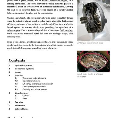
Torque Converter - Wikipedia 4d2g11
December 2019 65