Mit Electrical Electronics Open Ware 6.002-3 Handout S07015 Homework Hw2 565u58
This document was ed by and they confirmed that they have the permission to share it. If you are author or own the copyright of this book, please report to us by using this report form. Report r6l17
Overview 4q3b3c
& View Mit Electrical Electronics Open Ware 6.002-3 Handout S07015 Homework Hw2 as PDF for free.
More details 26j3b
- Words: 470
- Pages: 3
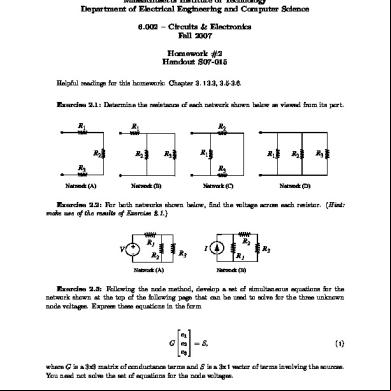
Massachusetts Institute of Technology Department of Electrical Engineering and Computer Science 6.002 – Circuits & Electronics
Fall 2007
Homework #2
Handout S07-015
Helpful readings for this homework: Chapter 3. 1 3.3, 3.5-3.6.
Exercise 2.1: Determine the resistance of each network shown below as viewed from its port.
R1
R2
R1 R2
R1
R3
R2
R3 Network (A)
R1
R2
R3
R3 Network (B)
Network (C)
Network (D)
Exercise 2.2: For both networks shown below, find the voltage across each resistor. (Hint: make use of the results of Exercise 2.1.)
V + -
R1 R2
I
R3
R2 R1
Network (A)
R3
Network (B)
Exercise 2.3: Following the node method, develop a set of simultaneous equations for the network shown at the top of the following page that can be used to solve for the three unknown node voltages. Express these equations in the form
⎡
⎤
e1 ⎢ ⎥ G ⎣ e2 ⎦ = S, e3
( 1)
where G is a 3x3 matrix of conductance and S is a 3x 1 vector of involving the sources. You need not solve the set of equations for the node voltages.
1 Cite as: Anant Agarwal and Jeffrey Lang, course materials for 6.002 Circuits and Electronics, Spring 2007. MIT OpenCourseWare (http://ocw.mit.edu/), Massachusetts Institute of Technology. ed on [DD Month YYYY].
e1 R2
V +-
R5
R1 e 2
R4 e 3
R3
R6
I
Exercise 2.4: Determine the power consumed by the 15Ω resistor in the network shown below. (Hint: use the series/parallel simplification method shown in Section 2.4 of the course notes.)
5Ω
4Ω
10V +
5Ω
15Ω
-
Problem 2.1: Find the Thevenin and Norton equivalents of the following networks, and graph their i−v relations as viewed from their ports. (Hint: use superposition for Network B.)
i
R2 +
+ v
R2
i
R1
V +-
v R1
-
I
V +-
Network (B)
Network (A)
Problem 2.2: Problem 3.9 from Chapter 3 of A&L (page 1 87).
2
Cite as: Anant Agarwal and Jeffrey Lang, course materials for 6.002 Circuits and Electronics, Spring 2007. MIT OpenCourseWare (http://ocw.mit.edu/), Massachusetts Institute of Technology. ed on [DD Month YYYY].
Problem 2.3: Two networks, N 1 and N2, are described graphically in of their i−v
relations, and connected together through a single resistor, as shown below.
(A) Find the Thevenin and Norton equivalents of N1 and N2.
(B) Find the voltages v1 and v2 that result from the interconnection of N1 and N2.
R
i1
N1
+ v1 −
i2 + v2 −
N2
1
v1
v2 V2 I1 i1
−I2
i2
−V1
(b) Network 2 (N2)
(a) Network 1 (N1)
3
Cite as: Anant Agarwal and Jeffrey Lang, course materials for 6.002 Circuits and Electronics, Spring 2007. MIT OpenCourseWare (http://ocw.mit.edu/), Massachusetts Institute of Technology. ed on [DD Month YYYY].
Related Documents 171j1w
Mit Electrical Electronics Open Ware 6.002-3 Handout S07015 Homework Hw2 565u58
November 2019 36
Mit Electrical Electronic Circuits Open Ware 6.002-2 Handout S07011 Homework Hw1 69f15
November 2019 62
Electrical Electronics 66384e
December 2019 60
Hw2 31n1g
December 2019 38
Hw2 31n1g
December 2019 40
February 2022 0
More Documents from "John Bofarull Guix" 2o3f3v
Altera Online Training Read First 6o2w6y
December 2019 44
Acronyms And Abbreviations - Businessball 4y592p
November 2019 201
Digital Signal Processing With Matlab 23252o
September 2020 0
Rae Poster 07 703k5i
April 2023 0
Mit Electrical Electronics Open Ware 6.002-3 Handout S07015 Homework Hw2 565u58
November 2019 36