Manual For Duct Air Conditioning Test Rig 4m6m6p
This document was ed by and they confirmed that they have the permission to share it. If you are author or own the copyright of this book, please report to us by using this report form. Report r6l17
Overview 4q3b3c
& View Manual For Duct Air Conditioning Test Rig as PDF for free.
More details 26j3b
- Words: 1,632
- Pages: 9
INSTRUCTIONAL MANUAL FOR
AIR CONDITIONING TEST RIG
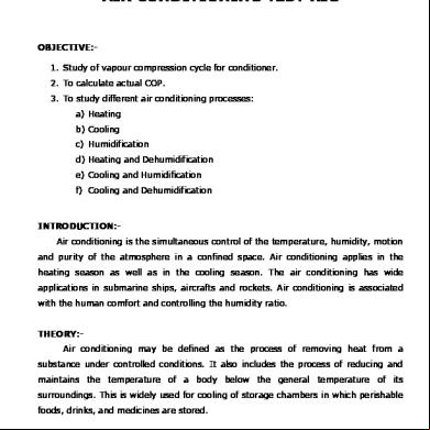
OBJECTIVE:1. Study of vapour compression cycle for conditioner. 2. To calculate actual COP. 3. To study different air conditioning processes: a) Heating b) Cooling c) Humidification d) Heating and Dehumidification e) Cooling and Humidification f) Cooling and Dehumidification
INTRODUCTION:Air conditioning is the simultaneous control of the temperature, humidity, motion and purity of the atmosphere in a confined space. Air conditioning applies in the heating season as well as in the cooling season. The air conditioning has wide applications in submarine ships, aircrafts and rockets. Air conditioning is associated with the human comfort and controlling the humidity ratio. THEORY:Air conditioning may be defined as the process of removing heat from a substance under controlled conditions. It also includes the process of reducing and maintains the temperature of a body below the general temperature of its surroundings. This is widely used for cooling of storage chambers in which perishable foods, drinks, and medicines are stored.
Simple Vapour Compression Figure shows the schematic diagram of simple vapour compression refrigeration system. It consists of following parts:
COMPRESSOR: The low pressure and temperature of refrigerant from the evaporator is drawn into the compressor through the inlet and suction valve as it is compressed to high temperature and pressure. This high temperature and pressure vapour refrigerant is discharged into the condenser through the delivery pipe. CONDENSER: The condenser or cooler consists of pipe in which the high pressure and temperature refrigerant is cooled and condensed. The refrigerant while ing through the condenser gives up heat to the surrounding which consists of condensing medium which is normally air or water. CAPILLARY TUBE: It expends the liquid refrigerant at high pressure to the liquid refrigerant at low pressure so that a measured quantity of the liquid refrigerant is ed into the evaporator. EVAPORATOR: It consists of coils of pipe in which the liquid vapour refrigerant at low pressure and temperature is evaporated and changed to the vapour refrigerant at low temperature and pressure. In evaporating the liquid vapour refrigerant absorbs the latent heat of vaporization from the medium which is to be cooled. Evaporator the liquid refrigerant by absorbing the heat into vapor refrigerant and sends back in to the compressor.
VAPOUR COMPRESSOR: The refrigerant start at some initial state or condition es through a series of processes in a definite sequence and return to the initial condition. This series of processes is called cycle.
The standard vapor compressor cycle (SVCC) consists of the following processes: 1. Reversible adiabatic compression from the saturation vapor to a super heated condition. 2. Reversible heat rejection at constant pressure (sub cooling liquid and condensation of the refrigeration) 3. Irreversible is enthalpy expansion from saturated liquid to a low-pressure sub cool liquid. 4. Reversible heat addition at constant pressure. DESCRIPTION: The air conditioning test rig unit is required to conduct experiments and demonstrate the process cooling of atmospheric air. The unit consists of a compressor. Both evaporator and the air cooled condenser are mounted on board with separate fans. Air is sucked from the room and is supplied to the room after cooling. The system is provided with voltmeter and ammeter, a digital temperature indicator. The unit will be fitted with all instruments facilities so that temperature and pressure can be measured at different points in the air conditioning system.
TECHNICAL SPECIFICATION:
Compressor Condenser Evaporator
: : :
Refrigeration : Fan Blower Set : Refrigeration :
Control
:
Digital Temp Air Velocity
: :
ISI Kirloskar Hermetically sealed compressor Fined Tube type air cooled condenser with fan Suitable for above compressor immersed in duct. Fins and Copper tube type cooling coil Freon R – 134a Standard make. a) Glass tube Rotameter b) Capillary tube expression devices. c) Filter cum Drier d) Suction & Discharge pressure gauge e) LP/HP cut-off a) Main Switch b) Digital Voltmeter c) Digital Amp. Meter d) Energy Meter e) Blower ON/OFF Switch f) Compressor ON/OFF Switch g) Heater ON/OFF Switch h) Boiler (Humidity) ON/OFF Switch RTD thermocouple for various temperature Indicator Digital Air Anemometer
The whole Set-up is mounted on a sturdy frame and base plate. UTILITIES REQURIED:
Electricity Supply: Single Phase, 220 VAC, 50Hz, 5-15Amp socket with earth connection.
TEMPERATURE SENSOR & ENTHALPY DETAILS:
T1 T2 T3 T4 T5
= = = = =
H1 H2 H3 H4 P1 P2
Inlet DBT
= = = = = =
Temperature Temperature Temperature Temperature Temperature
Enthalpy of Enthalpy of Enthalpy of Enthalpy of Pressure at Pressure at
Of Of Of Of Of
Compressor Inlet Compressor Outlet (Condenser Inlet) Condenser Outlet Evaporator Inlet Air Duct
refrigeration effects at Compressor Inlet, kJ/kg. compressor work at Compressor Inlet, kJ/kg. sub cooling at the outlet of Condenser, kJ/kg. refrigerant Inlet of Evaporator, kJ/kg. Compressor Suction, kJ/cm2. Compressor Discharge, kJ/cm2
= ………°F
=
(°F -32)/1.8 °C
=
…..°C
Outlet DBT = ……..°F
=
(°F -32)/1.8 °C
=
….. °C
PRECAUTIONS: 1. Before taking the readings ensure that the sensing bulb of wet bulb thermometer is properly wetted by soft cloth. 2. Do not start the heater while conducting the experiment for calculating COP. 3. Keep the heater ON during dehumidification process. STARTING PROCEDURE:1. Clean the apparatus and make it free from dust. 2. Ensure that all ON/OFF switches given on the are at OFF position. 3. Switch on the main supply. 4. Start the condenser fan motor. 5. Start the blower fan motor of the cooling coil (Evaporator). 6. Start the compressor. 7. Note down the readings of ampmeter, voltmeter, and energy meter. 8. Note down the readings of the various pressure gauges. 9. Note down the reading of DBT and WBT. 10. Take down the readings of Anemometer. 11. Take down the readings of various temperatures. 12. Note down the readings of Mass Flow rate of refrigerant through the Rotameter. 13. Switch ON the heater fitted in supply duct and note down readings. 14. Please note down that when the compressor should be OFF when the heater is ON. 15. Take readings. 16. Switch on the boiler to provide steam for humidification as required. 17. Note down the observations and calculate the COP. 18. While switching off the machine, first switch off the heaters off in services, switch off the compressor, condenser fan motor, blower fan motor, then switch off the main and then switch off the main board.
STANDARD DATA:1. 2. 3. 4. 5.
Air velocity Inlet air duct area Density of air 1 Bar Energy meter constant
= = =
= m/s 228x228mm = 0.05198 m2 1.162 kg/ m3 = 1 psi / 14.5 3200 Pulses/KWH
OBSERVATION & CALCULATION TABLE Sr. No.
Compressor Pressure (PSI) P1 P2 Suction Discharge
Temperature of Refrigerant oC T1
T2
T3
T4
T5
Temperature of Air (DBT) oC Inlet Outlet
Time taken for 10 Rev./ Sec.
Velocity of air m/s
1. 2. 3.
Sr. No. 1. 2. 3. 4. 5. 6.
PROCES SYSTEM Heating Cooling Humidification
INLET DBT
INLET WBT
OUTLET DBT
OUTLET WBT
REMARKS Only Heater ON Only Compressor ON Humidification (Boiler) and Blower ON Humidification (Boiler) and Heater ON Humidification (Boiler) and Compressor ON Dehumidification (Heater) and Compressor ON
Heating and Dehumidification Cooling and Humidification Cooling and Dehumidification
CALCULATION:1. Refrigeration effect ma
=
ma (Tai - Tao)
=
mass flow rate of air in kg/s
=
velocity of air x Inlet air Duct area x density of air
=
Specific heat of air (1.005)
Tai
=
Inlet temperature of air (DBT)
Tao
=
Outlet temperature of air (DBT)
2. Compressor Input
=
No of revolutions x 3600 ------------------------------------Time x Energy meter constant
3. Actual C.O.P.
4. Theoretical C.O.P.
=
Refrigeration effect -------------------------Compressor Input
=
H1 - H3 ----------H2 - H1
Mark points 1, 2, 3 using (P1, T2), (P2, T3), (P2, T4) respectively on P-h diagram from refrigeration chart and read H1, H2 and H3 (where H3 = H4) to calculate COP.
6. Relative C.O.P
=
Actual C.O.P ---------------------Theoretical C.O.P
Note that the COP of a heat pump depends on its duty the heat rejected to the hot sink is greater than the heat absorbed from the cold source, so the heating COP is 1 greater than the cooling COP. The maximum achievable COP would be 8.8. Test results of the best systems are around 4.5. When measuring installed units over a whole season and ing for the energy needed to pump water through the piping systems, seasonal COP's are around 3.5 or less. This indicates room for improvement. PRECAUTION & MAINTENANCE INSTRUCTIONS:1. 2. 3. 4. 5. 6.
Check the voltage. It should not less than 180 volt and more than 230 volts single phase 50Hz Ac supply. Do not run the compressor without switch on the fan motor. Do not switch on the heater without switch on the blower fan motor. Whenever the compressor is switched off. Do not switch on the compressor before five minute of interval. Mount Rotameter vertically and maintain upwards flow run. Avoid sudden opening/closing of the Hand shut off valve in the line to Prevent float hunting and possible glass tube breakage.
TROUBLESHOOTING:1. If electric is not showing the input on the mains light. Check the main supply. 2. If temperature of any sensor is not displays in D.T.I. check the connection and rectify that. REFERENCES:1. Arora C P, “Refrigeration and Air Conditioning”, 19th Edition, Tata McGraw Hill, Delhi (1985). 2. Pradad M, “Refrigeration and Air Conditioning”, 2nd Edition, New Age International Private Limited, Delhi (2002).
3. Dossat, R J, “Principles of Refrigeration”, 4th Edition, Pearson Education (Singapore), India, (2002). 4. Mcquiston F G, Parker J D and Spilter J D, “Heating, Ventilating, and Air Conditioning”, 5th Edition, John Wiley and Sons Inc, New York (2001).
AIR CONDITIONING TEST RIG
OBJECTIVE:1. Study of vapour compression cycle for conditioner. 2. To calculate actual COP. 3. To study different air conditioning processes: a) Heating b) Cooling c) Humidification d) Heating and Dehumidification e) Cooling and Humidification f) Cooling and Dehumidification
INTRODUCTION:Air conditioning is the simultaneous control of the temperature, humidity, motion and purity of the atmosphere in a confined space. Air conditioning applies in the heating season as well as in the cooling season. The air conditioning has wide applications in submarine ships, aircrafts and rockets. Air conditioning is associated with the human comfort and controlling the humidity ratio. THEORY:Air conditioning may be defined as the process of removing heat from a substance under controlled conditions. It also includes the process of reducing and maintains the temperature of a body below the general temperature of its surroundings. This is widely used for cooling of storage chambers in which perishable foods, drinks, and medicines are stored.
Simple Vapour Compression Figure shows the schematic diagram of simple vapour compression refrigeration system. It consists of following parts:
COMPRESSOR: The low pressure and temperature of refrigerant from the evaporator is drawn into the compressor through the inlet and suction valve as it is compressed to high temperature and pressure. This high temperature and pressure vapour refrigerant is discharged into the condenser through the delivery pipe. CONDENSER: The condenser or cooler consists of pipe in which the high pressure and temperature refrigerant is cooled and condensed. The refrigerant while ing through the condenser gives up heat to the surrounding which consists of condensing medium which is normally air or water. CAPILLARY TUBE: It expends the liquid refrigerant at high pressure to the liquid refrigerant at low pressure so that a measured quantity of the liquid refrigerant is ed into the evaporator. EVAPORATOR: It consists of coils of pipe in which the liquid vapour refrigerant at low pressure and temperature is evaporated and changed to the vapour refrigerant at low temperature and pressure. In evaporating the liquid vapour refrigerant absorbs the latent heat of vaporization from the medium which is to be cooled. Evaporator the liquid refrigerant by absorbing the heat into vapor refrigerant and sends back in to the compressor.
VAPOUR COMPRESSOR: The refrigerant start at some initial state or condition es through a series of processes in a definite sequence and return to the initial condition. This series of processes is called cycle.
The standard vapor compressor cycle (SVCC) consists of the following processes: 1. Reversible adiabatic compression from the saturation vapor to a super heated condition. 2. Reversible heat rejection at constant pressure (sub cooling liquid and condensation of the refrigeration) 3. Irreversible is enthalpy expansion from saturated liquid to a low-pressure sub cool liquid. 4. Reversible heat addition at constant pressure. DESCRIPTION: The air conditioning test rig unit is required to conduct experiments and demonstrate the process cooling of atmospheric air. The unit consists of a compressor. Both evaporator and the air cooled condenser are mounted on board with separate fans. Air is sucked from the room and is supplied to the room after cooling. The system is provided with voltmeter and ammeter, a digital temperature indicator. The unit will be fitted with all instruments facilities so that temperature and pressure can be measured at different points in the air conditioning system.
TECHNICAL SPECIFICATION:
Compressor Condenser Evaporator
: : :
Refrigeration : Fan Blower Set : Refrigeration :
Control
:
Digital Temp Air Velocity
: :
ISI Kirloskar Hermetically sealed compressor Fined Tube type air cooled condenser with fan Suitable for above compressor immersed in duct. Fins and Copper tube type cooling coil Freon R – 134a Standard make. a) Glass tube Rotameter b) Capillary tube expression devices. c) Filter cum Drier d) Suction & Discharge pressure gauge e) LP/HP cut-off a) Main Switch b) Digital Voltmeter c) Digital Amp. Meter d) Energy Meter e) Blower ON/OFF Switch f) Compressor ON/OFF Switch g) Heater ON/OFF Switch h) Boiler (Humidity) ON/OFF Switch RTD thermocouple for various temperature Indicator Digital Air Anemometer
The whole Set-up is mounted on a sturdy frame and base plate. UTILITIES REQURIED:
Electricity Supply: Single Phase, 220 VAC, 50Hz, 5-15Amp socket with earth connection.
TEMPERATURE SENSOR & ENTHALPY DETAILS:
T1 T2 T3 T4 T5
= = = = =
H1 H2 H3 H4 P1 P2
Inlet DBT
= = = = = =
Temperature Temperature Temperature Temperature Temperature
Enthalpy of Enthalpy of Enthalpy of Enthalpy of Pressure at Pressure at
Of Of Of Of Of
Compressor Inlet Compressor Outlet (Condenser Inlet) Condenser Outlet Evaporator Inlet Air Duct
refrigeration effects at Compressor Inlet, kJ/kg. compressor work at Compressor Inlet, kJ/kg. sub cooling at the outlet of Condenser, kJ/kg. refrigerant Inlet of Evaporator, kJ/kg. Compressor Suction, kJ/cm2. Compressor Discharge, kJ/cm2
= ………°F
=
(°F -32)/1.8 °C
=
…..°C
Outlet DBT = ……..°F
=
(°F -32)/1.8 °C
=
….. °C
PRECAUTIONS: 1. Before taking the readings ensure that the sensing bulb of wet bulb thermometer is properly wetted by soft cloth. 2. Do not start the heater while conducting the experiment for calculating COP. 3. Keep the heater ON during dehumidification process. STARTING PROCEDURE:1. Clean the apparatus and make it free from dust. 2. Ensure that all ON/OFF switches given on the are at OFF position. 3. Switch on the main supply. 4. Start the condenser fan motor. 5. Start the blower fan motor of the cooling coil (Evaporator). 6. Start the compressor. 7. Note down the readings of ampmeter, voltmeter, and energy meter. 8. Note down the readings of the various pressure gauges. 9. Note down the reading of DBT and WBT. 10. Take down the readings of Anemometer. 11. Take down the readings of various temperatures. 12. Note down the readings of Mass Flow rate of refrigerant through the Rotameter. 13. Switch ON the heater fitted in supply duct and note down readings. 14. Please note down that when the compressor should be OFF when the heater is ON. 15. Take readings. 16. Switch on the boiler to provide steam for humidification as required. 17. Note down the observations and calculate the COP. 18. While switching off the machine, first switch off the heaters off in services, switch off the compressor, condenser fan motor, blower fan motor, then switch off the main and then switch off the main board.
STANDARD DATA:1. 2. 3. 4. 5.
Air velocity Inlet air duct area Density of air 1 Bar Energy meter constant
= = =
= m/s 228x228mm = 0.05198 m2 1.162 kg/ m3 = 1 psi / 14.5 3200 Pulses/KWH
OBSERVATION & CALCULATION TABLE Sr. No.
Compressor Pressure (PSI) P1 P2 Suction Discharge
Temperature of Refrigerant oC T1
T2
T3
T4
T5
Temperature of Air (DBT) oC Inlet Outlet
Time taken for 10 Rev./ Sec.
Velocity of air m/s
1. 2. 3.
Sr. No. 1. 2. 3. 4. 5. 6.
PROCES SYSTEM Heating Cooling Humidification
INLET DBT
INLET WBT
OUTLET DBT
OUTLET WBT
REMARKS Only Heater ON Only Compressor ON Humidification (Boiler) and Blower ON Humidification (Boiler) and Heater ON Humidification (Boiler) and Compressor ON Dehumidification (Heater) and Compressor ON
Heating and Dehumidification Cooling and Humidification Cooling and Dehumidification
CALCULATION:1. Refrigeration effect ma
=
ma (Tai - Tao)
=
mass flow rate of air in kg/s
=
velocity of air x Inlet air Duct area x density of air
=
Specific heat of air (1.005)
Tai
=
Inlet temperature of air (DBT)
Tao
=
Outlet temperature of air (DBT)
2. Compressor Input
=
No of revolutions x 3600 ------------------------------------Time x Energy meter constant
3. Actual C.O.P.
4. Theoretical C.O.P.
=
Refrigeration effect -------------------------Compressor Input
=
H1 - H3 ----------H2 - H1
Mark points 1, 2, 3 using (P1, T2), (P2, T3), (P2, T4) respectively on P-h diagram from refrigeration chart and read H1, H2 and H3 (where H3 = H4) to calculate COP.
6. Relative C.O.P
=
Actual C.O.P ---------------------Theoretical C.O.P
Note that the COP of a heat pump depends on its duty the heat rejected to the hot sink is greater than the heat absorbed from the cold source, so the heating COP is 1 greater than the cooling COP. The maximum achievable COP would be 8.8. Test results of the best systems are around 4.5. When measuring installed units over a whole season and ing for the energy needed to pump water through the piping systems, seasonal COP's are around 3.5 or less. This indicates room for improvement. PRECAUTION & MAINTENANCE INSTRUCTIONS:1. 2. 3. 4. 5. 6.
Check the voltage. It should not less than 180 volt and more than 230 volts single phase 50Hz Ac supply. Do not run the compressor without switch on the fan motor. Do not switch on the heater without switch on the blower fan motor. Whenever the compressor is switched off. Do not switch on the compressor before five minute of interval. Mount Rotameter vertically and maintain upwards flow run. Avoid sudden opening/closing of the Hand shut off valve in the line to Prevent float hunting and possible glass tube breakage.
TROUBLESHOOTING:1. If electric is not showing the input on the mains light. Check the main supply. 2. If temperature of any sensor is not displays in D.T.I. check the connection and rectify that. REFERENCES:1. Arora C P, “Refrigeration and Air Conditioning”, 19th Edition, Tata McGraw Hill, Delhi (1985). 2. Pradad M, “Refrigeration and Air Conditioning”, 2nd Edition, New Age International Private Limited, Delhi (2002).
3. Dossat, R J, “Principles of Refrigeration”, 4th Edition, Pearson Education (Singapore), India, (2002). 4. Mcquiston F G, Parker J D and Spilter J D, “Heating, Ventilating, and Air Conditioning”, 5th Edition, John Wiley and Sons Inc, New York (2001).
Related Documents 171j1w
Manual For Duct Air Conditioning Test Rig 4m6m6p
December 2019 47
Hvac Air Duct Leakage Test Manual 291v1y
October 2022 0
Air Conditioning 713c6o
July 2022 0
Air Conditioning 713c6o
January 2022 0
Manual For Test Rig Im224.pdf x53t
December 2021 0
Refrigeration Air Conditioning Lab Manual 5u3v
December 2019 63More Documents from "BalRam Dhiman" 5d603j
Manual For Duct Air Conditioning Test Rig 4m6m6p
December 2019 47
How-to_ Author Disabled Presentations From Slideshare 5b3k3
November 2019 111
Analytical Crm 14k18
October 2022 0Customer Relationship Management Ppt n424y
October 2019 99
Principles Of Disaster Management Policy r4327
August 2021 0