Instruction Book Emcostar-emcorex 6h6z73
This document was ed by and they confirmed that they have the permission to share it. If you are author or own the copyright of this book, please report to us by using this report form. Report r6l17
Overview 4q3b3c
& View Instruction Book Emcostar-emcorex as PDF for free.
More details 26j3b
- Words: 15,306
- Pages: 45
Instruction book
emcB-stan
emcD-rex JC
3E
*
isK.
is — 1 ms i
IS
.....
©
:;BSQEI
I
%
I
-
r\ ■
i m C ’
i
I
a
«ir:
Jt'%
%
j
■
\:
V
■
I
II fed
?
a x
•*W
i
.
J
iiSs
Ml
1 ;
fj
ENGLISH Edition 7801 Ref. Nr. EN 2 620 I
f;: I
/'. 'r:! ! Halleii i/Ausin?.
•
1
TO
ASSEMBLE
YOUR
EMCQ
-
STAR
Take all the individual parts out of the box. Grip the EMCO-STAR by the electric motor and under the housing and lift it out of the box complete with the wooden frame. Unscrew the four wing nuts on the base of the machine; the EMCO-STAR can then be lifted off the wooden frame and placed on the bench or table. Unscrew the circular-saw cover with the aid of the tubular box spanner, erect the riving knife, and use the 5/16" dia-25/64" dia. locking pin to secure the saw spindle. Take the M 14 nut, the spherical washer, and the clamping washer off the spindle - the backing washer remains in place.
-
Fit the circular saw blade (the teeth point in the direction of rotation of the electric motor see the arrow on the motor), assemble the clamping washer, and the spherical washer on the spindle and tighten up the M 14 nut. Remove 5/16" dia-25/64" dia. locking pin.
Move the riving knife up until it is about
1/8 in.
clear of the saw blade and bolt it in place.
Now replace the circular saw cover and secure it. Unscrew the four socket-heat M 6 x 15 screws from the two segments M 6.00-33 Nut for the circular saw table, M 6.00-33 Nut for one segment, fit the table, and secure by means of the four socket-head screws. Then loosen the second segment and make sure that the table tilts freely. (If the table moves too easily, clamp both segments, loosen the socket-head screws, and tighten them up again with the segments still clamped). Place the table in its central position.
Fit the circular-saw guard in the square hole on the arm and secure by means of the knurled bolt, M 6 x 15. Make sure the cut-out for the riving knife is correctly located. Place the arm on the circularsaw cover and secure with M 6.00-33 Nuts.
The band-saw table is fitted in the
same way as
the circular-saw table.
Take the cover plate off the band-saw casing and remove the guard from the guide head. Fit the band-saw and thesanding belt (see Operating Instructions). Replace the band-saw guard and the cover plate on the casing.
Stick sandpaper to the disc-sanding plate. Fit the two guide bars into the bench stand and then slide them into the base of the machine and secure. The sanding table is to be mounted on the guide bars.
If desired, the EMCO-STAR can be bolted
to
the bench.
Fit the earthed plug (note that the green-yellow striped lead is the earth lead).
Read the instructions through carefully before starting
to use
the machine.
First of all you are to be congratulated on your choice of an EMCOSTAR woodworking machine. You have made a wise decision since the name EMCO is a guarantee of high quality and good design.
When using the Emco“Star either for professional purposes or as a handyman, please always pay attention to the mentioned serving instructions and safety precautions. ALWAYS USE TOOLS IN PERFECT CONDITION AND PROPER¬ LY SHARPENED. To familiarise yourself with the Emco-Star, read these instructions through carefully. You will find this of great assistance in showing you the easiest way of using the machine, while it is essential if the fullest use is to be made of its great versatility.
An Emco-Star fitted with all accessories will replace the following separate machines:
Circular saw, band saw, fret saw, jig saw, belt sander, disc sander, box combing, tongue and groove moulder, spindle moulder, lathe, drilling machine, tool grinder, and planer and thicknesser. In addition, drilling, sanding and polishing can be performed with a flexible shaft.
!
[
1 _
OVERALL DIMENSIONS OF COMPLETE MACHINE:
3/8" 27-9/16" 29-17/32" 81 1/2 lbs.
Length : Width : Height . Weight :
39
It is advisable to secure the Emco~Star to a bench which should be at least 39 x 1
27-9/16".
The height of the bench should be about 25
3/8"
5/8" .
CONNECTION TO POWER SUPPLY
The machine is supplied with the cable ends bare, no plug being fitted. In the case of single phase A .C . , the Green lead is to be connected to the earth on the plug . The machine
must
be plugged into
a
properly installed earthed socket.
The machine can be powered by either a single-phase or Stage 1 = 1500 r.p.m. at 0.37 kW (0,5 h.p.) Stage 2 = 3000 r.p.m. at 0 . 5 1 k W (0.7 h.p,)
a
three-phase A. C. motor:
The arrow on the
motor casing shows the correct direction of rotation of the motor. A three-phase motor might rotate in the wrong direction when it is plugged in; if this is the case, two of the phases in the plug will have to be interchanged, i.e, two of the connections will have to be interchanged
Arrangements should be made to make it impossible for the machine to be started up
by unauthorised persons MACHINE POSITIONS: To change the machine over from the "band-saw" to the "circular-saw" position and back (see arrows, Photo 1), it is merely necessary to tilt the machine. Stops limit the travel in both directions. The weight of the machine ensures that it is firm in both positions Hexagon bolt (M 6.00-06, Photo 1) must be slackened when the machine is tilted
The machine can also be clamped in any intermediate position by means of bolt M 6.00-06 (Photo 1) It is, for example, advisable to have the machine at an angle of 45° when using it as a spindle moulder If the machine is tilted into the "band-saw" position while the circular-saw is running, the clutch will automatically be disengaged. The saw blade will Then stop while the motor continues to run. The reverse applies when the machine is tilted
the other way ,
I
!
-2MACHINE BEARINGS:
All rotating parts are mounted in dust-proof permanently-lubricated ball bearings and require no maintenance. The longitudinally sliding parts of the fret-saw and jig-saw should, however, be lightly oiled at frequent intervals.
l
ACCESSORIES SUPPLIED WITH BASIC MACHINE
-.
mm ■
WM
y
'• ; ■
JÉÉ : ■
-06
i
circular-saw blade for rip-sawing and cross-cutting band-saw blade for cross-cutting jig-saw blade for wood sanding belt (grit 80) doz. emery papers, fine doz. fret-saw blades for wood tin adhesive tubular box spanner M 6.00-30 Allen key SW 5 DIN 911 1 locking pin M 6.00-24
1 1 1 1 1 1 1 1 1
M. r
RIPPING FENCE:
DM 6.00-30 1
fi
i
t
This is used to guide the components on the band-saw and circular-saw tables. To increase the bearing sur¬ face (which is often essential), an additional strip can be screwed to the main fence. This can be made of hardwood or hardboard about 5/15" thick. (Sketches A and B) (Drawing) Strip made of hardboard or wood
[
.
Extension Piece for Mitre Fence — 115-
-
-
T
Extension Piece for Ripping Fence a° -370
,
16
7 >
|— SO
60-~
-t150
Sketch A
60
t
•*
/
150
b
"
-200
S!J Sketch B
I
*7
1
EMCO
- STAR
USED AS A CIRCULAR-SAW
The circular bench saw is the most important woodworking machine. It sawing, cross-cutting, mitring, grooving, rabbetting, etc. DESCRIPTION OF PARTS:
Saw blade Saw table Fence Saw arm
can
be used for rip-
M 60.32 M 6.20 M 6.23 M 6.22 M 6.19 M 6.00-18
Guard Riving knife TECHNICAL DATA OF CIRCULAR-SAW:
:
1
Saw blade 7 3/8" dia. with 5/8" bore, 3/64" thick, Coarse-pitch blade for rip-sawing Medium-pitch blade for rip-sawing and cross-cutting Fine-pitch blade for cross-cutting
Speed of 1500 r.p.m. produces a cutting speed of 50 ft. /sec. Speed of 3000 r.p.m. produces a cutting speed of 103 ft. /sec. Table size 14 3/4" x 12", table cants up to 45° Rise and fall of table = 2 3/8" Max depth of cut: 2-5/32" Max width of cut without fence limited by saw arm: 7-31/64" Max width of cut using fence: 6-11/16" Max width of slot cut by wobble saw : 33/64" REMOVAL OF CIRCULAR-SAW BLADE:
KS 5
■V:
Hik ■
-y-r
.A
@
äSÿ&é M6.13
.
Tilt the machine to the "circular-saw" position. If the saw blade is to be changed, the table must first be raised to its highest position. Turning the handwheel M6.13 (Photo KS 1) clockwise raises the table, while turning the handwheel anti-clockwise lowers the table. The table will have attained its highest position when noticeable resistance is encountered to rotation of the handwheel. To illustrate the further operations required when changing the saw blade more clearly (Photo KS 2) shows the circular saw section of the Emco-Star with the saw table removed. First take off the cover plate and saw arm. This is done by unscrewing the two M 6.00-37 nuts by means of the tubular box spanner M 6.00-30; the cover can then be removed (Photo KS 3), and the saw blade is exposed. ICS 2
M6.21
V
M 6.00-24
.a'
ICS 3
a
.it»
Jr
M6.21
'1 A ? i i/r
M 6.00 -37 M 6,00-33
/
fa M 6.00-301 '
.
f M 6.12-0?
-w1
~y %
i VSj
/ÿ
- 4-
KS 4
M 6.00-24
The removal of the lock in c pm saw blade the saw spindle is illustrated in Photo KS 4 and Sketch 1 The spindle must first be secured by insert¬ ing the locking pin ; M 6.00-24 from above through a transverse hole in the spindle. saw spindle The saw blade should be turned by hand un¬ Sketch 1 til the locking pin can be entered into the hole. The nut can then be unscrewed by means of the box nut on
.
m
if
M 6.00-30
S? :....
f
1
■
spanner.
i
fj
KS 5
K \:
i
1 ) Hexagon nut
6031-6037 M 6.00 -22
Wm s M 600 -23 M 6 00-21
SEQUENCE IN WHICH PARTS ARE REMOVED FROM THE SPINDLE: (Photo KS 5)
M 6.00 -30
DIN 934 M 14
M 14 DIN 934 2) Spherical washer M 6.00-23 3) Clamping washer M 6.00-22 4) Circular saw blade 6031-6037 The backing washer M 6.00-21 on the spindle is removed only if if is to be replaced by the two wobble-saw washers for grooving or box-combing operations, or by the crank for the fret and jig¬ saw attachments.
[
PROJECTION OF SAW AND HEIGHT ADJUSTMENT: Sketch 2 10 mm
0
o~°
o
■o
The projection of the saw is illustrated in Sketch 2; if amounts to the thickness of the material to be cut plus 25/64". If, for example, a .590" thick board is to be cut, the projection should amount to .984". This will keep the area of the saw blade in with the work to a miminum and so prevent the blade overheating. When cutting uneven plywood sheets a larger blade projection will be required to eliminate the danger of the wood kicking back.
1
RISE AND FALL OF THE TABLE:
The table is raised an lowered by means of the handwheel M 6.13 (Photo KS 1). This allows the correct blade projection to be set or the fable to be raised to its highest position for changing the saw blades or for use of the machine for fret sawing and jig sawing. An hexagon head M 6.00-25 (Photo KS 1 ) is located in a hole in the casing cover plate above the sanding disc. If this is
tightened up by turning it clockwise by means of the box spanner, the table will be locked and be raised or lowered by the handwheel . Under normal circumstances, however, it will be sufficient to keep this hexagon head moderately tight, so that the height of the table can still be adjusted by turning the handwheel firmly. cannot
S
I
THE RIVING KNIFE AND ITS ADJUSTMENT:
Sketch 3
The riving knife (see adjacent sketch) is an important safety device on a circular saw. It prevents the saw kerf "clo" which could cause the wood to "kick back". The riving knife will be correctly adjusted when it is 5/64" - 3/32" clear of the tips of the teeth on the saw blade. The riving knife is secured by clamping bolts. The circular-saw cover plate should be removed to enable the riving knife to be adjusted.
1
OPERATING OF THE CIRCULAR SAW:
Sketch 4
;
The machine must be tilted to the "circular-saw" position. The ball handle (see sketch) is pulled away from the motor to engage the clutch. The clutch dogs will engage more easily if the sanding disc is turned by hand. The switch is moved through "Position 1" to "Position 2" (3000 r.p. m. ). The clutch must never be engaged Or disengaged while the
\
ax t x
1
motor is
4.'©a)
SAFETY PRECAUTIONS:
23
o
running.
.
Always use saw blades in perfect condition and free from cracks (i.e. properly sharpened and set). be firmly clamped on the saw spindle and its teeth must point in the correct
circular -saw
1
band-saw positions
2. The saw blade must direction. 3. The blade projection should be adjusted to suit the thickness of the material to be cut. 4. The riving knife must always be used and should never be removed. 5. The saw guard should always be set as low as possible. 6. The feed should be adapted to suit the material being worked. 7. Loose knots should be knocked out before sawing to avoid the danger of the wood kicking back. HINTS
FOR
USE
OF
THE
SAW:
RIP-SAWING WITHOUT A FENCE: The coarse-tooth blade should be used for rip-sawing. To prevent the wood binding on the saw, a curved piece must be laid with the convex side resting on the table. The cut pieces will then fall away from the blade (Sketch 5).
Sketch 5
]
:
CIRCULAR
RIP-SAWING WITH FENCE: Material can be cut T7T accurately to width only if one edge is / first trued up (Sketch 6). / The fence is then / set to the required / dimension as shown on the scale marked / on the saw table V (Sketch 6).
Sketch 6
m
m rT
i
\ ':N S'
KS 6 T
m
l-M
RIP- SAWING WITH TABLE CANTED:
SfeÿT*'
M
\Gsi
lb
M 6.00-33
i;
-6-
M 6.20ujppr
■j u
>
M 6.22
The circular-saw table (Sketch 7 and Photo KS 6) can be canted up to 45°. This enables bevel cuts to be made even on long compo¬ nents . To cant the table, loosen the two M 6.00-33 nuts; the table can then be canted to the desired angle as indicated by the protractor on the
segment .
Before each cut make sure that the two M 6.00-33 nuts are firmly tightened up (table might tilt).
-
. iM60.11
I; •
IM6O08
J
Sketch 7
CROSS-CUTTING LONG ITEMS: The medium-pitch saw blade should be used for cross cutting. The M 60. 1 1 is fitted in its holder (Photo KS 7) and set to the same height as the saw table. The M 60. 1 1 can then be pushed to the end of the guide bars M 6.27-02 (i.e. hard over to the right) and secured in place by tightening up the wing nut M 60.12-2.
* l
I
M 6.00-33
!
The saw arm M 6.22 should be removed by unscrewing the two nuts M 6.00-33, for cross-cutting long compo¬ nents .
!
CROSS-CUTTING SHORT ITEMS:
M 6.12.2
It is possible to cut off pieces at the required angle only if the mitre fence is used. The component should be held hard up against the mitre fence (Sketch 8). left-hand groove
a
1Ulf
right-hand groove
For cutting off long pieces of wood or to the wood more firmly is may be desirable to fit the mitre fence in the right-hand groove.
In this case, the saw arm must first be removed. If a large number of pieces are to be cut off it is- advisable to fit a deflector wedge to the table. This then deflects the offcuts away from the saw blade and prevents them
being thrown back (see Sketch 8).
Sketch 8
i
- 7-
MITRE CUTTING :
,lu Sketch 9
The circular saw is especially suitable for cutting mitres in flat frame (see Sketch). The mitre fence, against which the wood is held, must first be set to the required angle. If many mitre cuts are to be made, a deflector should be fitted. RABBETING ON THE CIRCULAR-SAW : For rabbeting, the ripping fence should be fitted with an extension to its bearing surface (Sketch A). A slow feed must be employed, since the saw dust cannot be thrown out over the top of the component. Sketch 10 shows the operations involved in rabbeting on the circular saw.
GROOVING ON THE CIRCULAR SAW; The circular saw can be used as a wobble saw if the saw blade is canted on the spindle by means of the two wobblesaw washers.
1st
FITTING THE CIRCULAR SAW BLADE WITH WOBBLE ATTACHMENTS: 1 . Remove the fable insert M 6.20-01 by unscrewing the two countersunk screws DIN 63 M 4 x 12 (Photo KS 8 and KS 9). 2. Remove the saw arm and the circular saw cover plate (see "Fitting and removing circular-saw blade"). 3. The saw blade and the backing washer on the spindle are
cut
2nd cut
]
Finished rabbet
removed. ]
Sketch 10 wobble-saw washers are placed on the spindle in place of the backing washer. 5. Fit the saw blade, the clamping washer, the spherical washer, and the hexagon nut, which should be tightened up only hand-tight (Sketch 1 1 A) . 6. Now adjust the relative positions of the two tapered wobble-saw washers until the saw blade is at the desired angle. 4. The
M 6.20-01
DIN 63 M4 *12 ■T
I •;
DIN 63 MV*12
two
The left-hand illustration
Sketch 1 1 A
Sketch 1 1
in Sketch 11 shows the blade set to the minimum
W
angle for wobble-saw work, while the right-hand illustration shows it at the maximum angle. If the full available adjustment is utilised a groove width of 0-511 “ :r obtainable
y o
- 8When the saw blade has been correctly adjusted, the nut is tightened up firmly using the box spanner while the spindle is held by the locking pin. For grooving, the projection of the saw blade above the table should be equal to the desired depth of groove. The groove width will be correct if it is about one-third the width of the wood. Sketch 12 shows the component and the ripping fence. The bearing sur¬ Sketch 1 2 face of the fence has been extended by fitting an additional strip to it. A medium-pitch saw blade should be used for grooving on the circular saw.
'ii -
r
MAKING A COMBED T: I
i1 !
The circular saw should be set up as a wobble saw. The combing attachment is fitted to the saw table. The combing bar is secured to the table by two clamping dogs and two knurled bolts (Photo KS 10). The slotted holes in the clamping dogs enable the clearance between the saw 9 blade and the combing bar to be adjusted. DIN 464 M 6 20
i
M 60 02-03 \
*
Combing is carried out as follows:
The height of the circurlar saw table is adjusted by means of the handwheel until the projection of the saw blade corresponds exactly to the thickness of the boards being combed. The component is then slowly pushed against the circular saw while it is held against the mitre fence and its edge runs along the combing bar (Photo KS 11). After the component has been returned to its initial position, it is moved over to the right, so that the groove that has just been cut bears against the combing bar (see Sketch 13). The second groove is then cut. The work described should first be per¬ formed on two short sample pieces of wood. An attempt should then be made to fit these two pieces together. If the grooves are too wide, so that there is too much play in the t, the combing bar should be moved away from the saw blade by an amount equal to the play. If the grooves are too narrow, so that the pins will not enter into the grooves, the combing bar is moved closer to the saw blade which reduces the width of the pins. When the combing bar has been adjusted a further set of grooves is cut in the sample pieces of wood and checked. Not until the combed t made in the sample pieces fits perfectly should a start be made on machin¬ ing the actual components. When the grooves have been cut in the first board, reverse it, and hold it with the first groove against the combing bar; the second board is then held against the edge of the first and fed into the circular saw by means of the I KS 10 mitre fence. In this way, the second board is displaced V by the width of one groove. In other words, where M 60.01 the first board has a pin, the second board will have «60.02-03 i PHS*> a groove, and the two will then fit together with £: flush edges. M 60.02-02
■
yp*
IF
-r:..
2221
i;
II
:
III!
-itch 1
•!
!
I
i
___
-9-
-
EMCO .v
M6.29
T.r
—
•:«
ss
M 6 DIN 466 M6.00-20
i
1
M6.1S
s
M 6.00-36
H
i
% ■
i
: 7*
STAR USED AS A BAND-SAW DESCRIPTION OF PARTS: (Photo BS 1) Star knob for adjusting blade tension M 6.29 Knurled nut M 6 DIN 466 Cover plate M 6.00-20 Guide head M 6.15 Band-saw table M 6.00-36
The material is cut by means of an endless steel band provided with saw teeth. The material is fed -through the saw by hand. The band-saw is suitable for rip-sawing, cross-cutting, and mitre cutting. With a narrow band-saw blade it is also possible to cut circles and curved lines. Slots and tenons can easily be cut with the aid of the adjustable parallel fence M 6.23. TECHNICAL DATA OF BAND-SAW:
JL
BS 2
y
M6 DIN 466
-
Saw blade 53.14" long, 1/64" thick, .390" .590" wide. For rip-sawing a gap-tooth saw blade .590" wide is most
suitable. For cross-cutting a gap-tooth fine-pitch saw blade 0.59" M 6.00 '20
M 6 DIN 466
fei •
j M6 PIN 466
wide is
most
suitable.
For cutting curves the most suitable blade is one with normal teeth .236" - .390" wide. Wheel diameter 6 7/8". A speed of 1500 r.p.m. produces a cutting speed of 45 ft./sec. A speed of 3000 r.p.m. produces a cutting speed of 90 ft./sec. Table size 9-27/32" x 1. 7/8", table cants up to 45°. Maximum depth of cut: 4-23/32". Maximum width of cut without fence: 5-29/32". Maximum width of cut with fence: 2-5/32"
.
FITTING AND REMOVING BAND-SAW BLADE: B3j
Removal :
M 6.29
m
1
mSl *
5|w p? ;
1
oj
Vw-w
.
The three knurled nuts M 6 DIN 466 (Photo B 52) are unscrewed by hand, and the cover plate M 6.00-20 is then lifted off the studs. It may be necessary to pull the pins on the lower band-saw guide apart before the cover plate is removed. This can be done if the two knurled bolts M 6 x 15 DIN 464 are slackened off (Photo BS 5). 2. The knurled bolts M 6 x 15 DIN 653 on the guide head M 6.15 (upper band-saw guide) (Photo BS 4) must be slackened off and the pins M 6.15-01 pulled apart. The band-saw guard can ‘•hen be simply pulled out of the 1
>
guide head. 3. By means of the regulating screw M 6.29 (Photo BS 3) it is possible to reduce the blade tension. A Ths raw blade w 'h=n carefully prH-=d off th? ’A'heelr through the slot in the table.
:
I
:
- 10 -
Fitting :
.
Place the saw blade on the wheels in such a way that the teeth are facing forwards with their tips pointing downwards onto the table. If the saw blade unwinds with the teeth wrongly positioned (which may occur if it has been turned inside out in its box while it is being packed), turn the blade inside out again like a stocking. 2. Adjust the blade tension by turning right the regulating screw M 6.29. The regulating screw will fall and reach with its metal ring M 6.00-47 the two marks on the lower spring tube M 6.00-48. When reaching the upper mark (A“B) the blade tension is correct for blades 1/4" and 3/8" wide. When reaching the lower mark (A~C) the tension is correct for all blades wider than 3/8". (Sketch 3). Note : Both excessive and insufficient blade tensions must be avoided, since these lead to early rupture of the blade. 1
;
A
A
■
M6.P9 If the knurled screw is turned clockwise, the band-saw blade will move to the right
A
knurled lock nut
A
4 A
4
. Turning screw anti -clockwise moves blade to the left
\
31-
A B
c
/ Sketch 3
Sketch 1
Sketch 2
M6.00-A7 M6.00-48
3. The next operation is to adjust; the upper guide wheel by means of the knurled screw (see Sketch 1) until the band-saw blade is
correctly positioned on the wheels. Sketch 2 indicates the correct position of the saw blade on the wheel. It will be noted that the tips of the teeth can project beyond correct wrong correct the edge of the wheel or at least must be flush with it. If the teeth are too far to the rear, the wheels and the tips of the teeth will be damaged. The adjustment of the band-saw blade will be simplified if the upper wheel is turned over by hand. As soon as the blade is correctly positioned on the wheels, tighten up the knurled lock nut to secure the knurled screw. Replace blade guard and locate onto pins M 6.15-01. Replace the cover plate and secure by means of the three knurled nuts.
4
4.
THE BAND-SAW GUIDE:
The band-saw guide is in
two parts,
accurate cutting. The two pairs of guide pins prevent
namely upper and lower, and is of great importance in ensuring the saw blade moving sideways.
ADJUSTMENT OF UPPER BAND-SAW GUIDE:
.
Loosen the two knurled screws (Photo BS 4, left hand). 2. Now push the guide pins (Photo BS 4, right hand) towards the saw blade until they are making r.~ ivc in rhi r ntact , A s'ight rubbing no:;.-:. ■, rn •’H; I CC’V (r I nr! ° Nrch 1
- 11
-
BS4
3. When the adjustment has been completed, tighten up the two knurled screws. 4. The back thrust wheel M 6.15-4 s the saw blade against the feed pressure. The knurled screw is loosened, and the back thrust wheel is moved against the back of the saw blade in a way, that there is a distance of 1/52". Then tighten up the knurled screw to secure the back thrust wheel .
AA 6.15.2
jMpTS DIN 653
f
é
ADJUSTMENT OF LOWER BAND-SAW GUIDE:
6.15 -01
The adjustment is made as follows: . The two knurled screws M 6 x 15 DIN 464 are slackened (Photo BS 5). 2. The guide pins are then moved towards the saw blade until they are just touching it. 3. When the adjustment has been cr- oleted, tighten up both knurled screws. 1
;Vv:
r
BS5 I
i
ADJUSTMENT OF HEIGHT OF GUIDE HEAD M6.15 (Photo BS 6)
To improve the cutting performance anc also as a safety pre¬ caution the guide head should be set as low as possible. It is most satisfactory if the bottom of the guide head rests gently on top of the component being cut. To adjust the height of the guide head, loosen the star knob M 6.24 with the right hand and raise or lower the guide head with the left hand. When the guide has ' een correctly positioned, tighten the star knob up again.
M6.00-141
ym
M 6.11-01 M 6*15
DIN464I
v
\
OPERATION OF THE BAND-SAW: 1 I |
M6.2A
1
ir
3S 6
.
2.
3.
4.
.
M6.1S
5.
..
Wt
The machine must be tilted to the "band-saw" position. Otherwise the clutch for the band-saw cannot be engaged. Push the clutch lever (Sketch 4, Circular saw section) towards the motor; turning the sanding disc by hand con¬ siderably simplifies the engagement of the clutch. Check the blade tension and the location of the band-saw guides by turning the band-saw round manually by means of the sanding disc. Switch on motor. Hard materials require a low speed (1500 r.p.m.) and slow feed - switch position 1 Soft materials can be machined at increased speed (3000 r.p.m.) and with a faster feed - switch position 2. If work is stopped for any appreciable time the saw blade tension should be relaxed. Re-tension before using as Fitting Note 2.
r T
3
- 12 SAFETY PRECAUTIONS:
.
Always use a saw blade that has been properly sharpened and set. 2. Check blade tension before switching on - see Fitting Note 2. 3. Set the upper blade guide as low as possible. 4. Do not use cracked saw blades; these can be recognised by the regular knocking noise they 1
emit.
POSSIBLE USES OF THE BAND-SAW: Most work on the band-saw will be performed with the table horizontal. If a bevel cut is to be made, however, the table should be canted the appropriate amount (Photo BS 5). If the hexagon nut M 6. 10-33 is loosened, the table can be canted up to 45° in one direction. A protractor scale simplifies the adjustment of the table. When the table has been correctly positioned, tighten up the hexagon nut again.
Other band-saw operations include cutting to length, rip-sawing, mitring, slotting and cutting curves.
It is advisable to use the rip-sawing fence for rip-sawing and slotting. For cutting to length and mitring use the mitre gauge. Here again, the fence can be provided with extensions. (As extension for Mitre Fence).
!
i
!
1
z
EMCO
DEC 1
M6.22
—
M6.19
1175
i
If
'
m
ii
*/
A M6.26
-
SÄ
M6.20
- 13 STAR USED AS A FRET SAW The fret-saw is used for marquetry work, for cutting smallradius curves, for cutting out figures, and similar operations. DESCRIPTION OF PARTS (Photo DEC 1) 1175 Fret-saw blade Holder-down M 6.26 M 6.19 Saw guard M 6.22 Saw arm Saw table M 6.20
T ECHNICAL DATA OF FRET-SAW .078" Saw blade width .510" Saw stroke 1 500 r . p. m. Speed Table size 14 3/4" x 12"
TO FIT SAW BLADE : Tilt the machine to the "circular-saw" position. W 1 . The saw guard M 6. 1 9 (Photo DEC 1 ) is raised to its highest position and secured by means of A Jk the knurled screw. A ZZMSMW \ 2. The circular saw table is raised as far as the " 130 stop permits. To prevent the table jamming in its highest position, turn the handwheel back im.- ' Jy[MEe-00-gW(>i half a turn. S31/ 3. The circular-saw cover plate and saw arm •W9W » are removed after the two nuts M 6.00-37 have been unscrewed. Now use the locking pin to l hold the circular-saw spindle, and remove the saw blade and all the washers (see section on circular-saw). The crank M 6.14 (Photo DEC 2) which is part DEC 3 of the equipment supplied with the basic machine, is fitted over the saw spindle in such a way that the 1/4" steel pin on its end engages in the hole in the reciprocating rod M 6.12.2A. Now secure the crank to DEC 4 prevent it rotating by ite tightening up the M 14 M 6.12 -05 hexagon nut by means of I M6.22-01A 4 the tubular box spanner M6*20DIN9t2T""ÿ M 6.00-30 (Photo DEC 2). ! It is then advisable to i rotate the circular-saw |;;.M 6*9.5 DIN 912» spindle by hand a few times to make sure that the saw stroking mecha“v-W* nism is working correctly. M6.22-0S While the cover plate is Igft/XAC ' removed it is advisable to oil the two bushes in which the reciprocating rod slides fz oetore starting work . Now replace the secure the cover
m
I*
"
D.K)
Ai..' .>
I
fiUk
mrnmmZ
sis*I
j
‘ml
sc*w. ann.
I
- 14 4. Loosen the two nuts M 6.00-33 under the circular saw table and cant the table to an angle '©f 45° (Photo DEC 3). 5. This simplifies the insertion of the saw blade. The bottom end of the fret-saw blade is first clamped in the reciprocating rod where it is held by a clamping and a socket-head screw (Photo DEC 3). The stop pin M 6.12-05 (brass) is pushed gently against the back of the saw blade and secured by the socket-head screw M 6 x 20 DIN 912. 6. The circular-saw table is returned to the horizontal position and held by means of the nuts M 6.00-33. 7. Fix the top end of the fret-saw blade in the spring-loaded rod by pushing the rod M 6.22-01 down with the thumb of the left hand until the upper end of the saw blade bears against the recess in the rod (Photo DEC 4). Screw up the clamping screw with the right hand. 8. Adjust the holder-down M 6- 26 and backing roller to the thickness of the material and secure by means of the knurled screw. The material must easily beneath the holderdown. OPERATION OF THE FRET-SAW:
.
1 Tilt the machine to the "circular-saw" position. 2. See preceding paragraphs for instructions on fitting crank and saw blade. 3. Check tension of saw blade and position of holder-down. 4. Pull clutch lever away from motor, rotating sanding disc until clutch engages (Sketch 4. Circular Saw section). 5. Lightly oil the reciprocating parts of the fret saw at frequent intervals. 6. Turn motor switch to position 1 (1500 r.p.m.)
!
[
I
s
I
__j
- 15 -
EMCO - STAR USED AS A JIG SAW DESCRIPTIONS OF PARTS: ST! 1
j#.
[
fj
Jig-saw blade for wood Circular-saw table
1180 M 6.20
The jig-saw can be used for straight and curved cuts and for making cut-outs even in large s (Photo ST 1). TECHNICAL DATA OF JIG-SAW:
j
" M6.20
Saw stroke Speed Table size Saw blades : wood plastics
.510" 1500 r.p. m. 14 3/4" x 12" coarse-pitch teeth medium-pitch teeth
TO FIT SAW BLADE: 1
.
2. 3.
4. 5.
First remove the saw arm. To do this, unscrew the two nuts and remove the saw arm and guard. Raise the saw table as far as the stop permits and then fit the crank as described in section 3 of the instructions for the fret-saw. The circular-saw table is then again canted 45°. With the table canted 45° fitting the saw blade becomes a simple matter. The blade is clamped between the reciprocating rod and the clamping plate by means of the socket-head screw (as for the fret-saw). Make sure the blade is vertical. A brass stop pin is fitted to the jig-saw blade in such a way that the back of the blade enters the slot in the pin and bears gently against the pin. Secure the pin in this position by means of the socket-head screw. The circular-saw table is returned to the horizontal position and secured by means of the two nuts M 6.00-33.
OPERATION OF THE JIG-SAW: 1 . Tilt the machine to the "circijlar-'saw" position. 2. If large components are to be handled, fit the M 60. 1 1 and set to the same height the table. 3. See preceding paragraphs for instructions on fitting saw blade. 4. Pull clutch lever away from motor, rotating sanding disc until clutch engages. 5. Turn motor switch to position 1 (1500 r.p.m.) 6. Lightly oil the reciprocating parts of the jig-saw at frequent intervals.
as
I
i
-
EMCO :
-
16
-
STAR USED AS A BELT SANDER DESCRIPTION OF PARTS:
■
€T> tf
Sanding belt Clutch Fence
M 6.23
A
■Y
60S)
V.
6051 M 6.08-05 M 6.23
.
M60B-05
WÄ m.
i
I
TECHNICAL DATA OF' BELT-SANDING ATTACHMENT :
y.
Sanding belt 31 7/8" long, endless, Fine Grit 100 Grit 80 Medium Grit 60 Coarse Pul ley diameter 3-35/64"
M6.24
6051 M 6x27 DIN 653
M 6 DIN 466
The belt sanding attachment provides an excellent means of smoothing all surfaces on small compo¬ nents that have been cut by the circular saw or band-saw (Photo BSCH 1).
M6DIN466
7ÿ i
1-37/64"
wide
At 1500 r.p. m. the belt speed is 23 ft. /sec. , and at 3000 r.p.m. 46 ft. /sec.
M6.17
Sketch 1 FITTING AND REMOVING SANDING BELT (Sketch 1)
Removal
.
Unscrew the three knurled nuts M 6 DIN 466 by hand so that the cover plate can be removed from the studs. 2. Slightly loosen the star knob M 6.24. 3. Relieve sanding belt tension by turning regulating screw M 6.17 anti-clockwise. 4. The sanding belt can now be removed from the pulleys. 1
i
|
Fitting
incorrect
correct Direction of belt travel
Direction of belt travel
Sketch 2
.
The sanding belt is placed on the two pulleys, attention being paid to the direction in which the belt t faces (see Sketch 2). If the belt is fitted the wrong way round the t will inevitably tear. 2. The tension of the belt is adjusted by means of the regulating screw (Sketch 1 , M 6. 1 7 - right hand) until the belt can still be deflected about 25/64" by finger pressure. 3. To maintain the belt tension at this value the regulating screw must be locked by means of the star knob (Sketch 1 , M 6.24 left hand). This star knob should not be slackened off more than is necessary to enable the regulating screw to be adjusted conveniently. 4. The sanding belt must not rub against either the casing or the cover plate. It must therefore be adjusted to ensure that it runs centrally on the pulleys. This adjustment is effected by means of the M 6 x 27 PIN 653 knurled bolt situated to the right of the (see Sketch 3),, 1
-
i
i
- 17 5. Replace the cover plate and secure with the three knurled nuts. 6. The belt can be adjusted to run centrally very easily while the machine is running, see Sketch 3. When the adjustment has been completed, secure the knurled bolt by means of the
knurled lock
nut.
If the knurled bolt is turned clockwise, the belt will move to the right
Knurled lock
\
3
nut
Turning the bolt anti-clockwise moves the belt to the left
Sketch 3
7. For sanding the narrow sides of components it is advisable to set the circular saw table about 3/8" - 19/32" higher than the sanding belt, and to move the circular-saw rip fence over un¬ til it overlaps the sanding belt by 1/16" - 1/8". This then provides a for the compo¬ nents during belt sanding (Photo BSCH 2). OPERATION OF THE BELT SANDING ATTACHMENT: BSCH 2
1
.
Tilt the machine
to
the "circular-saw"
position and cover the saw blade completely with the saw guard (Photo BSCH 2). 2. The circular saw table is raised as far as the stop permits. To prevent the table jamming in its highest position, turn the handwheel i
M6.23
M 608 -05™
5. 6. 7. 8.
6051
back half a turn. 3. Pull clutch lever away from motor, rotating sanding disc until clutch engages. 4. Engage clutch M 6.08-05 for belt driving pulley (Photo BSCH 1). This is done by pressing in the clutch button with the right thumb while the left hand pulls the belt
round; pulling the belt makes clutch engagement easier. Check belt tension. Check that belt is running centrally by turning sanding disc. Turn motor switch to position 2. On the completion of sanding, disengage the clutch M 6.08-05.
SAFETY PRECAUTIONS:
.
1 The circular-saw guard must be touching the table. 2. Make sure that the sanding-belt t is pointing in the correct direction. 3. Hold the component firmly during sanding. 4. Do not use torn belts. Very small components should preferably not be sanded on the belt sander, but s.:i.",e.- using the sunning falsie.
on
the disc
d
- 18
-
i
EMCO - STAR USED AS A DISC SANDER s )
t 'St- M
Tr
6.00-26
' i
TS
M
Sanding disc Sanding table Mitre gauge
|M <50.05
ii
X%
■
'
few
■
i M 6- 30
C
tv
DESCRIPTION OF PARTS:
M 6.00-26 M 6.30 M 60.03
The disc sanding attachment (Photo TS 1) is ideal for smoothing all surfaces that have been cut by the circular saw or band saw. It should always be used in conjunction with the sanding table. This enables even very small components to be sanded satisfactorily.
— M 6.12.2
To ensure that the component is pushed down onto the table by the movement of the sanding disc it is advisable to work on the right-hand half of the disc. With aid of the mitre gauge work pieces can be sanded as desired in any angle (Photo TS 1).
TECHNICAL DATA OF DISC SANDING ATTACHMENT:
Sanding disc = 6 7/8" dia. Abrasive paper: Grit 100 - fine Grit 80 - medium Grit 60
- coarse
[
The abrasive paper is secured to the sanding disc by adhesive. Speed of rotation: 1500 r.p.m. for hardwood or 3000 r.p.m. for softwood. Table size 7" x 8 5/7". [
FITTING THE SANDING TABLE:
.
Adjust the guide columns so that their ends project about 3 1/2" beyond the sanding disc. To adjust the guide columns, the nut must be loosened by means of the tubular box spanner M 6.00-30 and tightened up again when the columns are correctly located (Photo DRE 3). 2. Now the sanding table can be fixed on the guide bars in a way, that there is a distance between the front edge of table and the sanding disc paper of 1/20". 1
'ÿv
!
OPERATION OF DISC SANDING ATTACHMENT: 1 . Tilt the machine to the "circular saw" position.
2. Check that the guide columns and the sanding table are correctly positioned. 3. Place the clutch lever in the "0" position. (Sketch 4 Circular Saw Section). 4. Switch on motor, speed 1 or 2.
INSTRUCTIONS FOR FIXING THE EMERY PAPER:
The abrasive paper is fixed to the sanding disc by means of a adhesive. This adhesive is available in tins ready for use. Always keep the lids of the tins tightly closed. TO FIX EMERY PAPER: 1
.
Remove sanding disc. a) Unscrew knurled nuts on cover plate and remove latter. b) Unscrew hexagon-head bolt screw with tubular bolt spanner. a, ; ... off sanding disc.,
6
-19-
2. Clean the sanding disc and spread the adhesive evenly on both surfaces (the back of the abrasive paper and the sanding disc) by means of a brush or spreader. 3. The surfaces must now be left to dry for 1 0 to 20 minutes. The adhesive must be dry to the touch. 4. Place the abrasive paper in its correct position on the sanding disc and immediately apply pressure, it is sufficient to press down firmly with the flat of the hand. 5. Replace the sanding disc. When experience has been gained it will not be necessary to remove the sanding disc. In addition, up to three sheets of abrasive paper can be mounted on top of each other. When all three have worn out, remove them, cleaning off any remnants of paper and adhesive by means of a scraper. The sanding disc can be thoroughly cleaned with the aid of a suitable solvent. SAFETY PRECAUTIONS: 1 . The abrasive paper must be stuck perfectly flat on the sanding disc. Any irregularities would lead to rapid wear or tearing of the paper. 2. Replace worn abrasive paper by fresh. Worn abrasive causes burn marks to appear on the component being sanded. 3. If the abrasive paper tears dispose of it and fit a fresh sheet. 4. Move the sanding table close to the sanding disc. 5. Sand small components on the right-hand half of the sanding disc. As the disc rotates it will help to push the component down against the table. 6. Hold the component carefully and firmly.
-
M 6.00-26
&
Ik
:
7
M 60.03
Aoeoosfe
| M6.00-33 |M6»15DIN653
s» m-
-
M 60.05.4
The sanding table shown on the picture close by is adjustable in angle and height and can be supplied on demand. The sanding table is ed in the table carrier by means of two columns. The handwheel M 60.05.4 with its threaded spindle (Photo TS 1) serves as a means of adjusting the height of the table. Turning the handwheel clockwise raises the table; turning it anti~clockwise lowers the table. The two M 6 x 15 DIN 653 knurled screws enable the table to be secured at any height. If the M 6.00-33 hexagon nuts fitted at the sides are loosened, the table can be tilted up to 45° in either direction. A protractor scale
the segments simplifies this adjustment. When the table has been tilted to the desired position, the hexagon nuts are tightened up again. Before the table is placed on its columns, the hexagon-head bolt M 8 x 40 DIN 931 must be in¬ serted from above through the moulder table carrier, whereupon this is placed on the guide columns and secured by means of the clamping plate and the star knob. on
- 20 -
EMCO - STAR USED AS A SPINDLE MOULDER DESCRIPTION OF PARTS : FRAt
M 60.06.2 M 60.06.1
SÉ M 60.05
*
■
M 60.06.2 M 60.07 M 60.06.1 M 60.05
The moulding attachment (Photo FRA E 1) is used for moulding and rabbeting components.
\
M 60.071
Hand guard Cutter block Moulding fence Moulder table
TECHNICAL DATA OF SPINDLE MOULDING ATTACHMENT :
XM8*40 DIN 931
Cutter block diameter 3
l/4" width 1 3/16", two
cutters.
Speed: 3000 r.p.m. Cutting speed : 46 ft./sec.
MOULDER TABLE: Table size 7 7/8" x 15 3/4", rise and fall 2 3/8", tilting up to
45° in either direction.
FRAE 2
M6*1S DIN 653
M 60.06.-2
W: ■4
*
'
M 60.05-02
M 6.00.33
StM 60.05 V — /
r
'
FITTING CUTTER BLOCK: The cutter block M 60.07 is screwed onto the end of the motor spindle. The right hand holds the cutter block against the end of the spindle, while the left hand turns the sanding disc clockwise until the block is firmly screwed in place. To remove the cutter head it is held by the right hand using the locking pin, while the sanding disc is turned anti-clockwise by the left hand.
THE MOULDER TABLE :
The moulder table (Photo FRAE 1 , M 60.05) is ed in the moulder table carrier by means of two columns. The moulding fence M 60.06.1 is attached to the table by means of two knurled-head screws which are pushed up through the table from underneath. Two columns secured to the moulding fence carry the hand guard M 60.06.2, the height of which can be ad |usted. When the height of the guard has been set it is secured by means of two M 6 x 15 DIN 653 knurled-head screws (Photo FRAE 2). If the two M 6.00.33 hexagon nuts are loosened, the table can be tilted up to 45 in either direction. A protractor scale on the segments simplifies this adjustment. The height of the table is adjusted by means of a threaded spindle which is turned by the handwheel M 60.05.4. Turning the handwheel clockwise raises the table; turning it in the opposite direction lowers the table. The knurled screws fitted to the sides of the table carrier M 60.05-02 must be loosened before its height is adjusted and tightened up again afterwards. FITTING THE MOULDER TABLE: 1 Place the table on the two guide columns. 2. Insert the M 8 x 40 hexagon-head bolt from above through the moulder table carrier. 3. Attach the clamping plate on the underside with the star knob Hie complete. moulder table can now be slid along the guide columns towards the cuttes block. VV I i. he tehee correctly e-ore.; it is recue
.
-v,
- 21 SETTING UP THE SPINDLE MOULDING ATTACHMENT
Sketch 1 K hexagon
\
o
tubular box spanner M 6. 00-30
1 . For spindle moulding, the machine should be tilted to an angle of about 45° - see Sketch 1 . The machine is held in the tilted position by tightening up the M 6.00-06 hexagon on the end face of the machine by means of the tubular box spanner. 2. Screw the cutter block onto the end of the spindle. 3. Fit and secure .he moulder table. 4. Adjust the table to the correct height and secure. 5. Place the clutch lever in the "0" position. (Sketch 4 Circular Saw Section). 6. Switch the motor on to Stage 2 (3000 r.p.m.)
OPERATION OF THE SPINDLE MOULDER:
The moulder table is slid along the guide columns towards the beyond the fence by the width of the desired rabbet.
cutter
block until the latter protrudes
The depth of the cut is adjusted by altering the height of the table. The handwheel allows the height of the table to be adjusted with great accuracy. The guard will be correctly
set
when it is just touching the top of the components being machined.
The components are fed through the spindle moulder by hand, and should be employed.
a
steady and uniform movement
FITTING THE CUTTERS :
The cutters must be rigidly clamped in the cutter block by means of the socket-head bolts. The quality of the finish obtained will depend on the accuracy with which the cutters are set up. It is essential that the cutting edges of the cutters are equidistant from the centre of the cutter block, i.e. that the diameter of the cutting circle is the same for both cutters. This is achieved as follows: 1 . Insert both cutters in the cutter block with the smooth edges of the cutter towards the concave end of the block. The edges of the cutters should be flush with the end faces of the cutter block. The cutting edges should protrude about 5/64" beyond the circumference of the cutter
block . 2. The two cutters are held in this position by lightly tightening up the socket-head bolts. 3. The cutter block is now screwed onto the end of the spindle, and the height of the table should be adjusted until the cutting edge is flush with the table, i.e. until the edge of the first cutter projects by a fraction of an inch (perhaps .004") above the table. 4. A very smooth batten is now laid on the moulder table. As the cutter block is rotated by hand, this batten is carried by the first cutter, which projects very slightly above the table, from A to E. Mark the two points with a pencil. (See Sketch 2). Wood batten
m
+
é
» wm
A-E
Moulder table /
-22■
!
5. Return the batten to its initial position. 6. When the second cutter carries the batten the same distance from the initial position A to the final position E, both cutters will be correctly located. If necessary, the position of the second cutter will have to be corrected. 7. When both cutters have been correctly positioned, as indicated by the check, tighten the
socket-head bolts up firmly. 8. Form cutters are set up in the same way as straight cutters. GAUGE FOR SETTING CUTTER BLOCK: A considerably simpler method of setting the cutter block than that described above is to use the setting gauge M 60. 1 9 for ad justing the flat cutters in the block. This is effected as follows: The flat cutters are inserted in the block and are lightly held by screwing up the socket-head bolts very gently.
Now place the cutter block on the setting gauge with one blade M6 DIN 467 8 PIN 125 pointing towards the brass knurled \ M60.19-02 screw M 60. 1 9-02 (see sketch). \ / The cutter block is held in this / position by tightening up the socketi; head bolt M 8 x 35 DIN 912. The I knurled half nut M 6 DIN 467 is LI loosened, and the knurled screw turned back until the whole cutting / edge of the blade projects beyond the periphery of the cutter block. M60.19-01 This position of the screw is fixed by tightening up the knurled nut M 6 DIN 467. Then hold the cutter blade in with the knurled screw with one hand, and with the other secure the blade in the cutter block (with the aid of the Allen key). The socket-head bolt M 8 x 35 is then unscrewed, and the cutter block turned through 180°, so that the second cutter points towards the knurled screw. The second cutter is then pushed out until it is in with the knurled screw, which remains fixed, and secure. Both cutters are now adjusted to the same setting, and the cutter block can be removed from the setting gauge. To adjust moulding cutters PM 9 and PM 11 the knurled screw is inserted in the upper hold in the setting gauge. The other moulding cutters are dealt with in the same way as flat cutters. .
Sketch 3
M8 «35 □ IN9'2
i
I
SAFETY PRECAUTIONS: 1 Always use sharp cutters. 2. Screw the cutter block on firmly. 3. Make sure the cutters are always correctly positioned and firmly clamped. 4. Set the guard so that it just s the top of the components. 5. Loose knots must be removed from the wood before it is machined. 6. Do not use too deep a cut or too fast a feed. 7. The components must be pressed firmly against the table and against the fence while they are
.
being machined. 8. Small components should be fed past the cutters with the aid of up locally, and not directly by hand. 20
wooden push rod
St, ••
■'■nn
a
push rod (see Sketch 4) made
}
-
EMCO
Wk
- STAR
23
-
USED AS A WOOD-TURNING LATHE TURNING BETWEEN CENTRES: DRfc I
Description of parts:
«60.14
Two-prong driving centre Turning gouge Hand tool rest Tailstock
606$
Wr
«60.10
.
-
Tool
i
rest
holder
M 60.14 6065 M 60.09-M 60.10 M 60.12 M 60.08
This type of turning (Photo DRE 1) is particularly suitable for making long round articles such as skittles, chair legs, etc. The turning tool is ed on the large tool rest which has a length of 11 7/8” M 60.10.
M60.08 M60.12
1
FACEPLATE TURNING: M 60.09
/
6065
L
/
DRf. 2
Description of parts:
Faceplate
1Z0
■
Turning gouge
Hand tool rest Tool rest holder
.
M 60.13 M 60.65 M 60.09 M 60.08
This type of turning is used for making disc-shaped objects such as bowls, dishes, etc. The turning tool is usually ed on the small tool rest M 60.09.
M 60.08
«60.13
TECHNICAL DATA OF WOOD-TURNING LATHE: Height of centres 4 1/2" (max. diameter of workpiece 9") Distance between centre 19 5/8" Face plate 6 7/8" dia. Speed 1500 r.p.m. for surfacing and for longitudinal turning of components that are not perfectly balanced. 3000 r.p.m. for longitudinal turning of small-diameter components.
ri
rå
DEC 3
TURNING TOOLS: 6065 Turning gouge 6066 Turning chisel
SETTING UP THE WOOD-TURNING LATHE: & wm The two guide ft:
columns are pulled out to the right to their ful I est extent, the M 6.00-30 hexagon nut on the
«6.00
la-
/t
motor casing first being slackened off with the aid of the tubular box - - nn
3).
/p:
i
JH M60.12-02 fij J «6x15 DIN 653
r.
M 60.12.2ÿ
kl & M£2sJI ■
m
S «60.12
£01
«6.2
u
mm
i
1
- 24 -
.
The guide columns (Photo DRE 4, M 6.27-02) are ed by the bench stand M 6.27-01 The bench stand in turn can be screwed to the bench. SETTING UP FOR TURNING BETWEEN CENTRES: m The driving centre (Photo DRE 1 , M 60.14), which M 6.09 +M6.10 WS transmits the rotation to the workpiece, is screwed 5 :< onto the motor spindle (screw on clockwise). The hand tool rest (Photo DRE 5, M 60.09 or M60. 10) M6.09-0
f
•
DRE 5
•I
M60.13 DRC A
MAO.09
f
M 6.24
i*
m
M60.
M 60.12.2
3. 4. 5. 6. 7. 8.
F :
SETTING UP FOR SURFACING; The workpiece that is to be turned is secured to the faceplate M 60.13 by means of wood screws (Photo DRE 6). The illustration shows the faceplate screwed to the end of the spindle. (Screw faceplate on by turning it clockwise). The short tool rest M 60.09 will prove most convenient for surfacing. It is set up as described in connection with Photo DRE 5.
OPERATION OF THE WOOD-TURNING LATHE: 1 Tilt the machine to the "band-saw" position. 2. Pull out the guide columns to the required length. (If necessary screv' the bench stand to the bench).
.
driving centre or the faceplate. tool rest holder and tool rest. tailstock and adjust the distance between centres. the workpiece to the faceplate or between centres. Place clutch lever in "0" position. Switch on motor 1500 r.p.m. for surfacing and for unbalanced workpieces, 3000 r.p.m. for turning slender workpieces between centres.
Fit the Fit the Fit the Secure
SAFETY PRECAUTIONS : Drill centering holes in the ends of the workpieces. 2. Before switching on the motor make sure that the workpiece is firmly clamped and that the tailstock is correctly fitted. 3. Large workpieces and those that are unbalanced must only be rotated at a slower speed. 4. Set the tool rest as close to the workpiece as possible. 5. Hold the turning tool with both hands. : oss proper.y sharpen.-;!:.- von;s., 1
V-,/
.
I
i
- 25 -
EMCO - STAR USED AS A DRILLING MACHINE DESCRIPTION OF PARTS:
BO I
6030
M 6006.1
llppfcr
, -i
B?
Two-ja.v chuck Moulder Labi e Moulding fence Guide columns
M 60.05
•'1
_
mn
With the drilling attachment dowel holes can be drilled and slots cut. Holes can be drilled at an angle with the aid of the mitre gauge set at the desired angle, the moulding fence is then not required .
i
M 6.27-02
6030 M 60 . 05 M 60.06-1 M 6.27-02
j
TECHNICAL DATA OF DRILLING ATTACHMENT:
Two-jaw chuck capacity up to 1/2" Drills : Slotting cutter, four-cutter rim auger bit, twist drills. Speed : Slotting cutter 3000 r . p . m. , rim auger und twist dril Is 1 500 r p . m. Table : 7 7/8" x 15 3/4" tilts up to 45° in either direction. Rise and fall movement 2 trolled by handwheel.
.
3/8"
con-
FITTING TABLE:
This is described in detail in the section
on
the use of the machine as
a
spindle moulder.
INSERTING DRILL IN CHUCK Screw the two- jaw chuck (Photo BO 1 , M 6030 onto the end of the motor spindle by turning it
clockwise . Push the drill into the chuck M 6030 as far the square key.
as it
will go and then tighten up the jaws by means of
OPERATION OF DRILLING MACHINE: 1 . Tilt the machine to the "circular saw" position. 2. Screw the two- jaw chuck onto the end of the spindle. 3. Grip the drill in the chuck. 4. Fit the moulder table and secure it. 5. Adjust the table to the desired height and secure it. 6. Place the clutch lever in the "0" position. 7. Switch on motor (make sure it is running at the correct speed
- see above).
SAFETY PRECAUTIONS: 1 . Do not use bent or blunt drills. Insert the shank of the drill as far as possible into the chuck. As soon as the jaws have been tightened up remove the square chuck key. Adjust the table before starting the motor. Gu ide the workpiec firmly and careful ly .
2. 3. 4. 5.
:
- 26 SLOTTING:
M
a) Select a drill of the correct diameter (drill dia¬ meter about one-third thickness of wood). Moulding fence
c) Move the table towards the chuck (see sketch) so that the drill projects beyond the moulding fence by at least the deptb of the hole.
1 r Moulder table
OH OH
b) Set the table to the correct height.
d) The workpiece is ed against the mitre gauge (fitted with an extension piece) and slowly pushed towards the drill. Withdraw the workpiece at frequent intervals to clear the shavings . e) Drill holes one beside the other. The holes must not break into each other. The positions of the end holes are determined by the length of the slot.
f) Drill out the webs between adjacent holes.
g) Press the workpiece down against the table and slide it slowly along the moulding fence. (Sketch 1).
o* Sketch 1
I
I
-27-
EMCO
li
USED AS A TOOL GRINDER wz
* \
M60.04-02 M 60.04 '01
M 14x30 DIN 933
ri
*/
M 60.04 -03
- STAR
M 6.00 -21 M 6.00 -30
m ii&* M 6.27-03
M 6.24
1
DESCRIPTION OF Flange Grinding wheel Clamping washer Hexagon-head bolt Tubular box spanner Grinding rest Guard
Clamping plate Star knob
PARTS : M 60.04-03 6060 M 6.00-21 M 14 x 30 DIN 933 M 6.00-30 M 60.04-02 M 60.04-01 M 6.27-03 M 6.24
The tool grinding attachment is used for sharpening wood and metal-cutting tools.
TECHNICAL DATA OF GRINDING ATTACHMENT: Grinding wheel :
Thickness = 19/32" Bore = 3/4" Hardness : M The higher the grit number, the finer the wheel. The "hardness" of a grinding wheel determines the ease with which blunted abrasive particles are broken loose from the grinding wheel. Hardness "M" is suitable for sharphening normal tools. Speed : 3000 r.p.m. = 82.5 ft ./sec. Diameter = 6" Grit: 80
FITTING GRINDING WHEEL (Photo WZ 2) 1 WZ 2
M 6.00 -30 1
7
'
.
Screw the flange M 60.04-03 on the end of the motor spindle (turn it clockwise).
2. Place the grinding wheel on the flange. 3. Screw on the clamping washer and the hexagon-head nut by hand. 4. Hold the flange by means of the locking pin M 6.00-24 and tighten up the hexagon-head bolt with the aid of the tubular box spanner. Overtightening this bolt could cause the grinding wheel to crack or break. If the grinding wheel does not run true, clean it up with a dressing tool. The flange, grinding wheel, clamping washer, and bolt can be assembled as unit first, and the unit screwed on the end of the motor spindle (by turning it clockwise). FITTING THE GUARD (Photo WZ 3)
MMiai
The guard is placed on the guide columns and the clamping plate held against its underside. The guard is attached to the clamping plate by means of a hexagon-head bolt. The whole guard assembly is then slid up as close to the grinding wheel as possible, and secured by tightening up the star knob. The grinding rest M 60.04-02 should be moved close up to the grinding wheel. The gap should not exceed 7/64". When the grinding rest is correctly positioned, secure it by tightening up the nut. The
m
i
- 28 OPERATION OF THE GRINDING ATTACHMENT : WZ 3
1
.
_ M600V-02
--
to
the "band-saw" position.
2. Screw the grinding wheel onto the end of the
M 60.0» -01
A
Tilt the machine motor
spindle .
3. Fit and secure the guard.
M 6ÿ031
4. Adjust and secure the grinding rest. 5. Place the clutch handle in the "0" position.
7
6. Switch on motor, Stage 2 (3000 r.p.m.)
M6.A
: ;
SAFETY PRECAUTIONS WHEN GRINDING: 1
.
Dress the grinding wheel if it is running out of true.
2. Before fitting the wheel tap it lightly
to see
that it rings clearly (to check for cracks).
3. Tighten up the clamping flange with moderate pressure.
4. Always use the guard. 5. Move the grinding rest close up to the wheel
.
6. Run the machine for a short time before starting grinding to make sure it is correctly set up.
7. Always wear goggles when grinding.
1
- 29-
EMCO
-
STAR USED WITH A FLEXIBLE SHAFT ■
FI
The flexible shaft is used mainly for machining fixed workpieces which are too large to be worked on the machine.
M 6.00-24
6003
One end of the shaft is screwed onto the end of the motor spindle. The handle of the flexible shaft carries a "Gooddel" three- jaw chuck which can be tightened up to grip the tools by hand. A flexible shaft is available for use with the Emco-Star.
The flexible shaft has a length of 7", and the inner drive shaft has a diameter of 23/64". This shaft is capable of transmitting the full power of the motor. It can therefore be used for drilling holes up to 1/2" in diameter using drills with
.
turned-down shanks
FITTING FLEXIBLE SHAFT:
There is a female thread at the end of the flexible shaft and this can be screwed directly onto the end of the motor spindle which is held by means of the locking pin M 6.00-24 (Photo FL 1). To grip the tools, the shaft is held with one hand by means of the locking pin supplied which is applied behind the chuck while the chuck is tightened up to grip the tool by turning the knurled sleeve with the other hand. OPERATION OF THE FLEXIBLE SHAFT:
.
1 Tilt the machine to the "band saw" position. 2. Screw the flexible shaft onto the end of the motor spindle. 3. Fit the required fool in the chuck. 4, Place the clutch lever in the "0" position. 5. Switch on the motor and choose speed to suit the work.
SAFETY PRECAUTIONS:
.
1 The flexible shaft must be screwed onto the spindle as far as it will go. 2, Bent drills must not be used. 3. Always use sharp drills and cutters. 4. Before switching on the motor, hold the handle of the flexible shaft loosely.
i
1
- 30 COMBINED PLANER AND THICKNESSER
The EMCO-REX Planer and Thicknesser can be used either as an attachment to the Emco“Star or as an independent machine. The height of the bench should be about 23 1/2" to 26 1/2", depending on the height of the operator.
INSTALLATION OF THE EMCO-REX AS AN ATTACHMENT TO THE EMCO-STAR
.
Supplied with the EMCO-REX attachment are : M 60.20.8 Coupling M 60.20.5 Fence Assembly M 60.20.6 Guard Assembly 5 Socket-head bolts M 6 x 25 DIN 912
1 A I len key, SW 4 1 Al len key, SW 5
The individual parts are assembled as shown in sketch 1
.
MKXJ_
The coupling M 60.20.8 is placed on the free end of the planer shaft with the set screw M 8 x 8 DIN 916 located above the recess in the shaft. The set screw is then tightened up with the aid of the SW 4 Allen key. The two M 6.24 knobs are then un¬ screwed from underneath after which the two clamping plates M 6.27-03 can be removed (see sketch 2).
m.jpinsK
i M6x 20 DIN 912
4— -4- ;
/4-V
The planer is now placed on the guide of the Emco-Star, pushed to¬ columns wards the motor, and the coupling Sketch I boss (M 60. 20. 8~02, sketch 1) screwed onto the end of the motor spindle with the aid of the locking pin M 6.00-24. The rubber spider between the two halves of the coupling should have an axial play of about 1/32". When the planer is correctly positioned the two clamping plates are fitted and secured by tightening up the knobs. ■
MSP 20 04
i
M6 » 20 0;N9I2
The four screw feet (M 8 x 30 DIN 933 - sketch 2) are now adjusted so that they rest on the table and bring the coupling M 60.20.8 into alignment. The two halves of the coupling must be accurately aligned; if there is any radial misalignment the rubber spider will be subject to rapid wear and the machine wil I vibrate in service. Once the screw feet have been correctly adjusted they are locked by tightening up the nuts (M 8 DIN 934), sketch 2. Now the fence assembly (M 60.20.5) is secured by means of three socket-head bolts c _ (M 6 x 25 DIN 912) as shown in M60. 20 - 01 M60.20J__ sketch 1 to the infeed table H60. 20. 2 V (M 60.20-04), sketch 2, and the V ‘O' guard assembly (M 60.20.6) by =1 means of two socket-head bolts to the outfeed table (M 60.20-05). The MS H DIN 934 _ SW 5 Allen key provided is used to MS 27 -03 M6* 30DIN933 tighten these bolts. If you have ordered Sketch 2 the SUVA guard for the planer this M)
.
,
is
r i rved g n piece err i
;r
c
i
r
,<
L
i ..
noiTnCi: guor’. ■, /
l
I
}
-31
-
(M 6 x 25 DIN 91 2) to the side of the outfeed table.
The planer is now completely assembled and ready for use. Turn the motor switch to stage 2 (3000 r.p.m.). When the Emco-Star is being used for other work it is advisable to disconnect the planer. To do this, loosen the two knobs and slide the planer 3/4" - 1 3/16" away from the motor. The two halves of the coupling will then disengage, and the planer shaft will not rotate.
-
I
I - 33 .
EMCO-REX SURFACE PLANER
Technical data: Cutter head 2 27/32" dia. with 3 knives 1 3/16" x 1/8" x 8 Cutting circule diameter of knives 2 29/32" Speed 3000 r.p.m. as an attachment Cutting speed 39 1/4 ft/sec Speed 3700 r.p.m. as an independent machine Cutting speed 47 ft/sec Planing width 8" Max. depth of cut 7/64" Length of table 26 3/4"
1/4"
} }
The surface planer is used for planing boards and battens, for bevelling, and for ting. Front table (infeed table) Back table (outfeed table) Cutting circle Workpiece Depth of cut
workpiece
back table
front table
2
;
a=
depth of
cut
'
3
cutting circle
Sketch 5
The depth of cut
to
2 3 4
The knives are set so that they are exactly flush with the back table (Sketch 5, No. 2). If, as shown in Sketch 5, the front table is set lower than this by an amount "a", a strip of thickness "a" will be planed off the workpiece. The height of the front table M 60.20-04 is adjusted by turning the knob M 60.20.3 (Sketch 2).
which the machine is set is shown on a scale M 60.20-22 at the side (Sketch 2).
CORRECT OPERATION OF SURFACE PLANER
The required depth of cut is set by raising
or lowering
the front table by
means of
the knob M 60.20.3
(Sketch 2). On average, it will be found advisable to set the depth of cut to 1/32" (maximum 7/64") since this setting the planed surface will be much smoother than at 7/64".
at
For planing, the workpiece is laid on the front table, pressed down with both hands, and slowly pushed against the cutter head. As soon as the front of the workpiece has ed the cutter head, this end should be pressed down onto the back table with one hand while the other continues to push the workpiece against the cutter head.
The concave side of a board is always planed (see Sketch 6). If the board were laid down convex side on the table, it could not be held level while it is fed over the knives.
with its
To plane an edge (narrow side of board), the fence is fitted square to the table surface. The board is then held with the planed face pressed against the fence and it is oushed with a ■jnhwry; pressure over the carter hc-no (see .tioivch 7),
I
■i
- 34 The knives should
as
far as possible be covered by the guard.
Small workpieces should be fed through the planer with the aid of a home-made pusher to prevent injury to the hands. Sandpaper can be stuck to the underside of the pusher to make it grip better (see Sketch 8). The fence fitted to the planer is adjustable across the table and also for height; in addition, it be canted up to 45° in either direction, and is fitted with a protractor.
can
The fence can therefore be used for planing bevels on narrow edges. The transverse adjustment of the fence is particularly useful since it enables the full width of the knives to be utilised.
---
If the fence were always left in the same
place when planing narrow workpieces, the knives would soon become blunt. Sketch 6
SAFETY PRECAUTIONS FOR SURFACE PLANERS
;
1 . The cutter block should be covered by the
guard to the fullest possible extent; this applies in particular when ting and when planing narrow workpieces. 2. Always use sharp knives. This greatly reduces the danger of the workpiece
kicking back. Sketch 7
[
3. Always use a pusher when feeding small workpieces through the machine.
4. Use the palms of the hand and not the tips of the fingers to press the workpieces down against the table.
A
I
5. Before starting to feed a workpiece through the planer clear away any shavings from the tables by blowing or by brushing them with a piece of wood. Sketch 8
P
*
Sketch 9
.
- 35 EMCQ-REX THICKNESSER
Technical data :
Planing width 8" Max. thickness of workpiece Max. depth of cut Automatic feed Table length
5/32" 7/64" 13,1/8 ft/min. 23 5/8" 2
The thicknesser is used for planing boards and battens parallel .
to a
desired thickness with the opposite faces
The cutter block is situated above the table.
The workpiece is automatically fed through the machine by mechanically-driven feed rollers.
M 60. 20. A A
mm 2
M60.20-12A
J|
M60. 20-11 M 60. 20-08
1
'4
Thicknessing table
Sketch 10
Fluted roller Cutter block Outfeed roller Anti-kickback device The workpiece rests
on
1
2 3 4
the table M 60.20-01, sketch, the height of which can be adjusted.
The depth of cut is regulated by means of the handwheel M 60.20.2. A graduated scale M 60.20-23 the side enables the required thickness of cut to be set.
at
The feed roller fitted in front of the through the machine.
cutter
The outfeed roller located behind the
block is fluted
cutter
so
that the workpiece is automatically fed
block is smooth to avoid marking the machined surface.
CORRECT OPERATION OF THICKNESSER 1
.
Before being ed through the thicknesser all workpieces must be planed on one face. This is essential to ensure that the finished items are flat.
2. Place the planed board on the table with its unplaned side uppermost and push it forward until it s the fluted feed roller. :
'
"v
of non-uniform fh: rkness shouio aivvayr
;>a
fad in wife the vi sicker
enc<
lending. Tin's
- 36 prevents them jamming in the machine.
4. If the maximum depth of cut of 7/64" would have feed the workpiece into the machine.
to
be exceeded it will
not
be possible to
5. If large amounts are to be removed, several es through the machine will therefore have to
be made.
6. If a workpiece jams while ing through the machine (excessive depth of cut), lower the table about 1/32" by means of the handwheel, and the workpiece will continue to feed through
the machine.
7. When machining narrow workpieces (battens) do not always lay them in the same place on the table, but make full use of the width of the knives.
8. Clean shavings and other dirt off the table at frequent intervals. 9. If after some time the friction becomes excessive and a workpiece fails to feed through, the planer tables will have become coated with resin (occurs particularly when machining fir). It will then be necessary to clean the table with a rag soaked in turpentine. Then wipe the table dry and rub in paraffin. Do not rub in oil, since the wood would soak this up and would then become unsuitable for glueing, staining or painting.
10. If very thin boards are to be machined (less than 3/16"), these should be laid on board 3/4" thick, and the two ed through the machine together. 11
.
a
planed
The Emco-Rex gear box is filled with a special viscous gear grease and greased for life. If grease should be lost when opening the gear box or for any other reason, only a self¬ liquid and viscous gear grease (KLUBER-LUBRICATION St 15/400 PPa) must be refilled. The complete filling quantity is about of 1/5 lbs.
E
SAFETY PRECAUTIONS FOR THICKNESSERS 1
. 14 anti -kickback thepawls
are fitted over the full width of the table on the EMCO-REX thickoperator from injury by workpieces that are kicked back. 1 Anti-kickback pawl
nesser to protect
Fluted roller Workpiece mo. 2o -ii
1
If boards of different thicknesses are
M60.20-08
beeing machined simultaneously, the thinner pieces could be kicked back; this is prevented by the anti“kickback pawls. They allow the components to in the normal direction of feed, but press them down against the table and hold them if they try to move back¬ wards
1
2
3 ///////
2 3
E
/'///7//7///7/ZV////7///////7///S/////////77/////////
.
2. Cover the cutter block with the sections of the guard.
Sketch 1 1
3. Keep a look out for nails and other foreign bodies in the workpieces and remove any that are present.
4. Do not workpieces shorter than 4 7/8" in length through the thicknesser, since these would not be properly gripped and guided by the outfeed roller. ■ ■
i'
Viien
finishing work, lower the thicknesser table
-----
it
ec:s;e. to
dean off all shavings.
as
far as possible by means of the handwheel
6
I
- 37 NOTES ON WORKPIECES
The boards are usually stood up with their ends resting on the ground. As sand and small stones tend to become lodged in the ends of the boards, and these can damage the knives, trim off the rough ends of the boards with the circular saw before ing them through the planer. Workpieces should be ed through the planer and thicknesser with the grain, since this produces
a smoother finish (see sketch 12).
W
V,
%
///// Sketch 12
1
wrong
correct
SHARPENING (TOUCHING UP) THE PLANER KNIVES If a lot of saw dust is produced in addition to shavings when planing it is a sign that the knives are no longer sharp. In this case it is possible to sharpen the knives without removing them from the machine using a fine oilstone (size about 1" x 19/32" x 3-15/16"). The stone is oiled and is then placed on the cutter block as shown in sketch 13. The stone is pushed uniformly to and from over the length of the knives under a gentle pressure until the knives oilstone are sharp again .
pill
:
REPLACING AND SETTING THE PLANER KNIVES
When the machine has been in use for some time, the knives may have become nicked by small stones lodged in the workpieces. In such a case Sketch 13 raised lines will be observed on the boards after planing. Planer knives that have nicked cutting edges or that have become so blunt that they can no longer be sharpened by touching them up with an oilstone while they are in the machine, will have to be removed and reground. It is an advantage to have a set of three spare knives that can be fitted and used while waiting for the original set to be reground. 1 . To remove planer knives
Lower the front table to its fullest extent to make access to the 4 bolts (socket-head M 6 x 15) that secure the knives easier. The bolts that secure one knife are fher unscrewed with the aid of the " Al ien key, and the planer knife (M oCAlO 09) is relieved I» .gether with the backing jar K) sketch A ) ; . . i , r. : ru. i.j. c.: • ; i r . M,.
..............
...... ..
i i q
- 38 M 6 x 25 DIN 46+
M8x 30 DIN417
\
M 60.20.7
two knives are removed in the same way. The grooves on the cutter block, as also the knives and backing bars should be thorougly
cleaned.
M8 DIN 934
2. Fitting reground planer knives
One planer knife is inserted in the groove in the cutter block together with its backing bar, and the four socket-head bolts are tightened up very gently. A straight edge is then laid on edge on the fixed back table, and the cutter block is turned until the knife is in its highest position. Both ends of the knife must then touch the straightedge. If this is not the Sketch 14 case, the knife must be adjusted by tapping its projecting ends with the bolts still tightened up sufficiently to prevent it slipping, until it is level with the straightedge. Now tighten up the four socket-head bolts, and fit the setting gauge (M 60.2.7, sketch 14) securing it to the cutter block with the knurled-head screw (M 6 x 25 DIN 464). The two brass screws (M 8 x 25 DIN 464) should now just the cutting edge at both ends of the knife. If this is not the case, the gauge should be adjusted accordingly. This is done with the gauge in place by loosening the two hexagon nuts and turning the brass screws until they do the cutting edge. The hexagon nuts are then tightened up to lock the screws in this position. Once the gauge has been adjusted for a particular machine it should not be altered and it can then be used on subsequent occasions to set the knives correctly without the aid of the straightedge. Each of the other knives is then fitted as described above; it is, however, not necessary to use a straightedge to locate the knives. Instead the setting gauge is fitted, and the projecting ends of the knives are pushed up with a screw-driver until the cutting edges the brass screws on the setting gauge. The bolts are then tightened up to secure the knife in this position, the gauge is removed, and the procedure is repeated until all four knives have been fitted and set.
mm-' Z/m
j
If you do not possess a setting gauge it is possible to set all four knives using initially described). This, however, takes considerably more time.
a
I
straightedge (as I
f
39
STANDARD ACCESSORIES FOR MORTISING AND SPINDLE MOULDING
.
Mortise and Moulding Table 2. Clamping Ring 3 Length Stop 4. 1 pair Wood Clamps 1
.
TO PREPARE THE MORTISE ATTACHMENT FOR U
:
Remove Bar Bracket from basic > machine Place Length Stop and Table Assembly and Lever Clamp over bars. Fit Lever to table Replace Bracket and secure. Fit both Wood Clamps to table. Screw Chuck into position on motor spindle and fit Mortise Slotting Bit (up to 1/2" diameter). Secure work in hand to table by means of wood clamps. Adjust depth of slot with Length Stop. Height adjustment is carried out by means of the hand wheel
.
m
Chuck
M60.24.5
.
M60. 24-01
j /
M60.24.2
Y
.
Adjust length of slot by means of the stop spindle and knurled nuts. (Always fix knurled nuts counter-wise) It is advisable to cut the mortise by repeat cuts of 1/2" until the full depth is obtained.
.
TO PREPARE MOULDING ATTACHMENT FOR USE
Remove both wood clamps and exchange with hold-down clamp (special accessory). Screw on Moulding Head to spindle of »
•
motor.
Moulding Head M60.25.1
ii W*
M60.25.2
1 V
To fix table
IMPORTANT !
Fix Moulding Table in position and adjust depth and height as required.
•
When .Moulding, the table must be securely clamped. Work is fed by hand,,
.
Secure Moulding attachment with Toggle Screws to bars of basic machine
.
2. Fix Moulding Table in adjustable position by means of knurled nuts on stop spindle
.
40
CIRCULAR
1
SAW
BLADE
GRINDER
. Fix
the shaped grinding wheel in the grinding wheel holder and screw onto the spindle end of the EMCO-5TAR.
the motor (speed 1500 r.p.m.) and trim the face (plane surface) with the truing stone until it is clean.
2. Switch
on
3. Remove the tool from the wheel guard. Now screw on the circular saw blade grinder with its conical bearings on the bearing block of the wheel guard (Figure 4) . Push the grinder, together with the wheel guard, as far as possible towards the grind ing wheel .
4. Detach the work-location fixture (knurled nut, spring, and centering cone - Figure 1) :
.
5. With the feed spindle, adjust the distance between the arbor and the locking pawl so that it matches the radius of the circular saw blade. 6. Insert the circular saw blade with the tips of its teeth pointing clockwise.
7 . Place the centering cone into the bore of the circular saw blade, and then clamp the saw blade with the spring and knurled nut. I
8. Adjust the sliding block so that the back of the tooth is at the right angle to the grinding stone axis. Refix the sliding block (Figure 1). 9. Adjust the tooth depth with the feed screw. 10. Bring the back of the teeth up to the grinding wheel by turning the feed spindle (Figure 2) . 1 1 . For grinding, the machine is switched on (speed 3000 r.p.m.) and the circular saw blade held with the right hand so that the tooth rests against the locking pawl under pressure. The lever of the grinder is swung slowly upwards with the left hand until it
reaches the stop. 12. The circular saw blade is fed forward by slowly turning the feed lever until a slight grinding action starts on the clearance angle surface of the tooth.
13. Now that the circular saw blade grinder has been prepared for use, it is swung out and turned anti-clockwise along to the next tooth. The gripping lever now engages. While the circular saw blade is held with the right hand so that the tooth presses against the locking pawl, the grinder is swung in again with the left hand, and the next tooth is ground, and so on.
After grinding a circular saw blade for the first time, some teeth may not be clean. In this case the blade is fed in once more with the feed lever, and the process repeated.
The circular
saw
blade grinder
'c
suitable for circular saw blades 4'1
-
10" diameter.
I
m
—
grinding wheel
-te =4locking pawl
-
•
Hi i
base plate
- 41 -
knurled nut
spring
Fig. 1
centering cone
sliding block
JPT*Si \ feed spindle
41 a
i
r
knurled nut for clamping sliding block feed screw conical bearing
clearance angle
clearance angle
t\ i
gullet toothed
(
pointed toothed
Fig. 3
%
wheel guard
&ÿ
\
shaped grinding wheel
Fig. 2
XT'S
-•■ * *
*
,
«
*
•
circular saw blade
*
-"’..v
shaped grinding wheel
\
IHå
OfT
+
r
.1 IIOIIIIli
m
Fig .4
column sleeve
■
6 \
H
1
-!i.
bcarine Mock nedeoa! crossbar mu
43
STROMLAUFPLAN WECHSELSTROM (SINGLE PHASE) Emcostar R
Mp
o
SI
O
—
I
Njj 544* i
:
i13 1C
■
a
/
rV
'
:
I
I
_
L
__
i
w
k1
T
i
\
75
\
16
1
13 K
b1
Tie
T)HÖ
\l1
Ys
' >5
\1
' >7
Tie
f
U4
~Y
\2
w4
fu2 U4 V4
= rot = blau
red
blue
grey = grau brown Up = braun Vp = schwarz brown Wp =orange orange
W4
b1 0 1 2 0 1 2
1 2
3
X
X
4
8
X
X
X X
X
7
5 6
9 10
11 12
13 14
15 16
X X
X
X
X
X
X
X X
44
STROMLAUFPL AN DREHSTROM (THREF PHASE) Emcostar (
Mp
T
S
Q
R
SI
Q)
Q
O
O
I
€>
!
V ' , VA \ ■
,/
t i
<
!
I
v,
o 75
i V
b1 ft/;
■
\
Tb 13
12
\
1
:
i
\: \
V
T>10
E
I
J
I
vy2
w4
U4
rot -= blau
W4
= grau = braun
V4
V4
red blue grey
brown V 2 = schwarz black W? = orange orange
P b1 1 0 2
1
3
5
2
4
6
7 8
X
X
9 10
11 12
13 14
X
X
X
15 16 X
X
X
1
Related Documents 171j1w

Hatz Diesel Instruction Book 3z6j6a
December 2021 0
Es360 Instruction Book 384sv
March 2021 0
Dms2 Ge Instruction Book d2i4u
November 2019 39
Tdr94 94d Instruction Book s295j
November 2019 92
Instruction Book Emcostar-emcorex 6h6z73
December 2019 48
Life's Little Instruction Book 2r6om
October 2019 46More Documents from "Johan Leide" 6401e
Instruction Book Emcostar-emcorex 6h6z73
December 2019 48
Som Do X.docx 32s4l
September 2022 0
2c82t
November 2019 32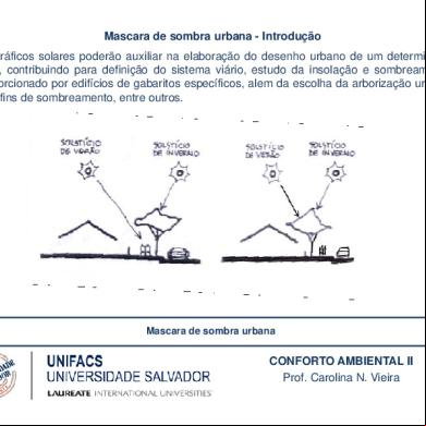
Mascara De Sombra Urbana 1q5g3j
March 2021 0
Aprenda Como Fazer Hamburguer Gourmet.pdf 3c2s2w
October 2019 74