Floating Breakwater Design 2os2t
This document was ed by and they confirmed that they have the permission to share it. If you are author or own the copyright of this book, please report to us by using this report form. Report r6l17
Overview 4q3b3c
& View Floating Breakwater Design as PDF for free.
More details 26j3b
- Words: 4,391
- Pages: 15
FLOATING BREAKWATER DESIGN By Bruce L.fMcCartney,1 M. ASCE
ed from ascelibrary.org by University of Leeds on 08/12/13. Copyright ASCE. For personal use only; all rights reserved.
'(f) ,,_ ABSTRACT: {Floating breakwaters are inventoried. The various types are separated into 4 general categories, wMehSale Box, Pontoon, Mat, and Tethered Float. The Tethered Float was identified as a special category but lacked sufficient prototype experience for detailed analysis. Advantages and disadvantages of the Box, Pontoon and Mat are presented. Hydraulic model test results and prototype experience for these 3 types are presented. Alternative mooring systems and anchorage methods are summarized. The engineering studies ttstt* aBy^needed for a suitable design are outlined. Costs and design data for selected prototype installations are tabulated.-]
INTRODUCTION
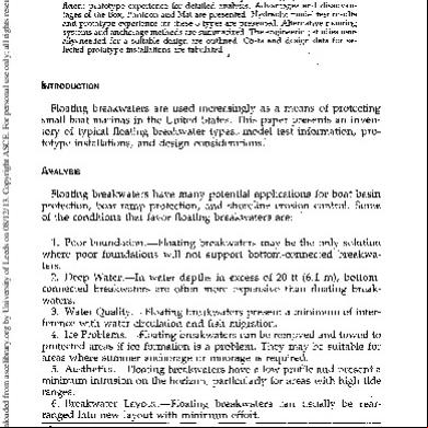
Floating breakwaters are used increasingly as a means of protecting small boat marinas in the United States. This paper presents an inventory of typical floating breakwater types,, model test information, prototype installations, a n d design considerations." ANALYSIS
Floating breakwaters have m a n y potential applications for boat basin protection, boat r a m p protection, a n d shoreline erosion control. Some of the conditions that favor floating breakwaters are: 1. Poor Foundation.—Floating breakwaters m a y be the only solution where poor foundations will not bottom-connected breakwaters. 2. Deep Water.—In water depths in excess of 20 ft (6.1 m), bottomconnected breakwaters are often more expensive t h a n floating breakwaters. 3. Water Quality.—Floating breakwaters present a m i n i m u m of interference with water circulation and fish migration. 4. Ice Problems.—Floating breakwaters can be removed and towed to protected areas if ice formation is a problem. They may be suitable for areas w h e r e s u m m e r anchorage or moorage is required. 5. Aesthetics.—Floating breakwaters have a low profile and present a minimum intrusion on the horizon, particularly for areas with high tide ranges. 6. Breakwater Layout.—Floating breakwaters can usually be rearranged into n e w layout with m i n i m u m effort. a Hydr. Engr., Hydr. and Hydrology Div./ Office Chief of Engrs., U.S. Army Corps of Engrs., Washington, D.C. 20314. Note.—Discussion open until August 1, 1985. To extend the closing date one month, a written request must be filed with the ASCE Manager of Journals. The manuscript for this paper was submitted for review and possible publication on August 30, 1982. This paper is part of the Journal of Waterway, Port, Coastal and Ocean Engineering, Vol. I l l , No. 2, March, 1985. ©ASCE, ISSN 0733-950X/ 85/0002-0304/$01.00. Paper No. 19610.
304
J. Waterway, Port, Coastal, Ocean Eng. 1985.111:304-318.
BOX
ed from ascelibrary.org by University of Leeds on 08/12/13. Copyright ASCE. For personal use only; all rights reserved.
SOLID R E C T A N G L E
R E I N F O R C E D CONCRETE UNITS A R E T H E MOST COMMON T Y P E .
S T A N D A R D B A R G E SIZES ON I N L A N D WATERWAYS A R E 195' X 35' X 12' A N D 1 7 5 ' X 26' X 1 1 ' I N C L I N E D BARGES (ONE E N D SU BMERGED1HAVE BEEN T E S T E D . PONTOON
TWIN P O N T O O N
FLO TAT/ON BALLAST
C A T A M A R A N SHAPE
ALSO C A L L E D ALASKA
OPEN COMPARTMENT
TYPE
•*- WOOD SHEET SECTION
nr.
^M=
•*
DECK IS OPEN WOOD FRAME.
MAT S C R A P T I R E S S T R U N G ON P O L E F R A M E W O R K OR B O U N D T O G E T H E R WITH C H A I N OR B E L T I N G . FOAM F L O T A T I O N IS U S U A L L Y N E E D E D .
T I R E MAT
L O G R A F T C H A I N E D OR CABLEDTOGETHER.
TETHERED
FLOAT
FLOAT TETHER ANCHOR - / '
F L O A T S P L A C E D IN ROWS. V
PLATFORM ^
SECTION
=•
ARRANGEMENT SIMILAR TO SPHERES. S T E E L DRUMS WITH B A L L A S T S C A N B E USEO IN L I E U O F T I R E S .
FIG. 1.—Various Types of Breakwaters 305
J. Waterway, Port, Coastal, Ocean Eng. 1985.111:304-318.
ed from ascelibrary.org by University of Leeds on 08/12/13. Copyright ASCE. For personal use only; all rights reserved.
FLOATING BREAKWATER TYPES
In recent times, many types, of floating breakwaters have been modeltested and some have been constructed. Ref. 8 provides a comprehensive survey of floating breakwater types. These breakwaters can be subdivided into four general categories: box, pontoon, mat, and tethered float. Some floating breakwaters in each category are shown in Fig, 1. The box, pontoon, and mat types have considerable model and prototype experience, which is summarized in this paper. The tethered float is only identified as a unique type worthy of a separate category. However, since the known published information (summarized in Ref. 8) is experimental, the tethered float breakwater is not examined further in this paper. PROTOTYPE PERFORMANCE
Performance of prototype installations was recently investigated for the east and west coasts of the U.S. These surveys (2,14) showed that used tire mats were used primarily on the east coast and concrete box or pontoon types, on the west coast. The tire mats had a high failure rate or exhibited poor performance due mainly to placement at sites where wave forces exceeded the mooring system capacity, flotation material was lost, or flexure failure of connection materials occurred. Better analysis of site conditions and a proper engineering design of the tying materials and mooring system could decrease the failure rate. Although modular connection and mooring hardware are their weaker points, the concrete box or pontoon breakwaters have generally performed satisfactorily; however, their first cost is considerably higher than tire breakwaters. Life cycle costs between various types of floating breakwaters have not been developed. TIRE MAT BREAKWATER
Three types of tire mats have been model-tested and constructed: Wave Maze, Goodyear, and Wave-Guard (also called Pole-tire and pipe-tire) as shown in Figs. 2-4. Advantages of the tire mat'breakwater are: (1) Low cost; (2) easily removed and beached for maintenance or to prevent ice damage; (3) can be constructed with unskilled labor and minimal equipment; (4) lower anchor loads than box type; and (5) much lower reflected waves than box type. Disadvantages are: 1. Lack of buoyancy.—Loss of trapped air in tire crown, marine growth, and silt accumulation in tire bottom can sink the breakwater. In order to ensure flotation, foam is usually needed for extra buoyancy and regular maintenance is needed to control marine growth. Holes in tire bottom can be used to prevent or reduce silt accumulation. 2. Design life.—Design life of the tire breakwater is still unknown. A properly designed breakwater and mooring system with adequate maintenance may have a 15-20-yr life. 3. Limited application.—Present use has shown that tire mat breakwaters are only effective in mild wave climates (less than 3-ft high, 3308
J. Waterway, Port, Coastal, Ocean Eng. 1985.111:304-318.
ed from ascelibrary.org by University of Leeds on 08/12/13. Copyright ASCE. For personal use only; all rights reserved.
FIG. a.-r-Wave Maze (Ref. 11) , Cornet tires are .rotated 100°
Note: Each individual module is 1.98 by 2.13 by 0.76 m.
'
FIG. 3.—Goodyear (After Ref. 7)
B-
<=*=*=*(II 3 S l
B
ocDcajn n
ngggEjK^acz^r,
] J J [ JrCZHmcZKZIKZZH-
Q
-H
CHAIN
3 §
- o o o ( [ JJ ANCHOR
Q-
TIRE-STRING
J [ ]}CZHZ3C=M=K=>-
-H
fl flf1)c=H^H=H=H=i-
-Q
=
-CZMZ3C3{[]J
FIG. 4.—Wave-Guard or Pipe Tire (After Ref. 10)
307
J. Waterway, Port, Coastal, Ocean Eng. 1985.111:304-318.
1.0
1 H
1
i
1
1
1
1
P
/L<*0-04
1
1
1
v
ed from ascelibrary.org by University of Leeds on 08/12/13. Copyright ASCE. For personal use only; all rights reserved.
r
GOODYEAR-
„ -
^-WAVE-GUARD
C, 0.5
Dt (cm) GOODYEAR WAVE-GUARD WAVE-MAZE i
1
0
i
i
I
2
H=WAVE HEIGHT l_ = WAVE LENGTH B = BREAKWATER WIDTH p = BREAKWATER DRAFT d=WATER DEPTH W (cm)
D/d
d/L
8.415 50-380 .06-.44 0.4-1.4 8.4 100 .06-;23 .10-.26 15 71-309 ,25-.52 .09-.69 1
1
1
1
1
1
3 L
B/D
1
7-42 14 5-11 1
i—
4
/W
FIG. 5.—Comparison of Wave Coefficient, c,, versus Wavelength-to-Breakwater Width, L/W, for Wave Maze, Goodyear, and Wave-Guard Scrap Tire Floating Breakwaters (After Ref. 9)
sec period waves). Wide mats or a series of unconnected mats may extend application to more severe wave climates. 4. Litter entrapment.—Field experience shows the tire mat breakwaters tend to accumulate floating debris, which some consider unattractive. Fig. 5 shows the wave attenuation performance of the Goodyear, Wave Maze, and Wave-Guard breakwaters. Caution must be used in extrapolating the L/W (wavelength-to-breakwater width) parameter for design. Final design generally is based on "model" or "prototype" tests of the site-specific proposed mat dimensions and predicted wave climate. Refs. 7 and 10 present prototype scale wave tank tests of the Goodyear and Wave-Guard breakwaters. Model test data for the Wave Maze are found in Ref. 11. Box
BREAKWATER
Most box-type breakwaters have been constructed of reinforced concrete modules. The modules either have flexible connections or are preor post-tensioned to make them act as a single unit. Modular and mooring connections are primary points of concern for this type of design. Presently installed floating box breakwaters have a cross section less than 25 ft (7.6 m) wide with 5 ft (1.5 m) or less draft. Large units can be made either of steel or concrete. New or use^d barges may be suitable when large units are needed. Standard barges built for the inland waterways are 175 ft (53.3 m) long, 26 ft (7.9 m) wide, and 11 ft (3.4 m) deep. Jumbo barges are 195 ft (59.4 m) long, 35 ft (10.7 m) wide, and 12 ft (3.7 m) deep. Barges 175 ft (53.3 m) by 26 ft (7.9 m) cost about $230,000 new, and the 195 ft (59.4 m) by 35 ft (10.7 m) barges cost about $300,000 new (1981 prices). Used barges can be purchased for 50% or less than new 308
J. Waterway, Port, Coastal, Ocean Eng. 1985.111:304-318.
ed from ascelibrary.org by University of Leeds on 08/12/13. Copyright ASCE. For personal use only; all rights reserved.
FIG. 6.—Physical Model of Solid Rectangular Box-Type Floating Breakwater Evaluated In Two- and Three-Dimensional Wave Flume for Potential Application at Olympia Harbor, Washington (Ref. 4)
OPEN HOPPER BARGES LENGTH FEET
BREADTH FEET
DRAFT FEET
CAPACITY
26
9
JUMBO
175 195
1000
330-290
35 40-52
9
JUMBO
1500 2500-3000
LENGTH FEET
BREADTH FEET
DRAFT FEET
CAPACITY
STANDARD
175
26
9
1000
JUMBO
195
35
9
1500
TYPE STANDARD SUPER
9
TONS
COVERED HOPPER BARGES TYPE
TONS
INTEGRATED CHEMICAL AND PETROLEUM BARGES LENGTH FEET
BREADTH FEET
DRAFT FEET
CAPACITY TONS
FIG. 7.—Predominate Barge Sizes in United States (Ref. 12)
costs. Other barges are made up to 300 ft (91.4 m) long, 54 ft (16.5 m) wide, and 12 ft (3.7 m) deep. The barges could be ballasted to the desired draft with sand or rock. Some prototype (1) and model (5,13) tests have been made of barges with one end submerged to form an inclined pontoon breakwater. Fig. 6 shows a typical surface-type concrete unit, and Fig. 7 shows typical barges used on the inland waterways system. Advantages of the box-type breakwater are: (1) 50-yr design life; (2) unit will allow pedestrian access for fishing and temporary boat moorage; (3) simple shape to build (however, construction requires a high degree of quality control); (4) proven performance; and (5) effective in moderate wave climate. 309
J. Waterway, Port, Coastal, Ocean Eng. 1985.111:304-318.
1 MODEL SCALE: BTWT DlMEN-
V ed from ascelibrary.org by University of Leeds on 08/12/13. Copyright ASCE. For personal use only; all rights reserved.
N w • n FT •
\V
•A
1 : 10
1
12- ANO 16-FT WIDE 96-FT LONG 5-FT DEEP 3.5-FT DRAFT
WAVE CONDITIONS: H = 1.5 - 3.5 FT T = 2.S - 4.0 SFC d = 25 FT
inurr
-
ANCHOR CHAINS; CROSSED
\
V-
FIG. 8.—Wave Transmission Coefficient, c,, versus Breakwater Width to Wavelength, W/L, for Box-Type Breakwater Tested for Olympia Harbor, Washington (After Ref. 4) Disadvantages are: (1) High cost compared with the mat type; (2) maintenance, if damaged, may require towing to dry dock; and (3) connectors can be a problem if not adequately designed. Fig. 8 shows the wave attenuation performance of the box-type breakwater. The caution of using the L/W (or W/L) parameter discussed above
\ \
W FIG. 9.—Module of Open Compartment (Ladder Type) Floating Breakwater Used In Two-Dimenslonal Model Study of Olympia Harbor, Washington (Ref. 4)
FIG. 10.—-Twin-Pontoon (Catamaran Type) Floating Breakwater Considered for OaSc Harbor, Washington (Ref. 6) 310 ^i J. Waterway, Port, Coastal, Ocean Eng. 1985.111:304-318.
ed from ascelibrary.org by University of Leeds on 08/12/13. Copyright ASCE. For personal use only; all rights reserved.
2J-FT 120-FT 6-FT 4.5-FT
WIDE LONG DEEP DRAFT
FIG. 11.—Wave Transmission Coefficient, c,, versus Breakwater, Width to Wavelength, W/L, for Ladder Type Breakwater for Olympia Harbor, Washington (After Ref. 4)
also applies to box-type breakwaters. Large deviations can be expected in attenuation coefficients when moorings are modified due to development of harmonics in the spring mass system. PONTOON BREAKWATER
A typical pontoon type (also called Alaska or ladder type) is shown in Fig. 9. A smaller, less expensive twin pontoon (catamaran type) is shown in Fig. 10. Advantages and disadvantages of the pontoon breakwater and caution on L/W (or W/L) parameter are similar to the box type. See Fig. 11 for wave attenuation data on the ladder type and Figs. 12 and 13 for the wave attenuation and mooring force data on the catamaran type. MOORING
Floating breakwater can be held in place by: (1) Piling, which allows the breakwater to rise and fall with the tide but not move laterally; (2) concrete mass or ship anchors and line; or (3) stake piles and line. The three types of moorings are shown in Figs. 14-16. Pile-anchored breakwaters are limited to fairly shallow sites [about 30-ft (9.1-m) water depth] and require suitable bottom material to allow adequate pile penetration and sufficient lateral strength. Stake piles can be steel H beams or timber. Generally, they are driven below the mud line to develop the greatest strength and prevent destruction of wood piles by marine borers. Stake piles are suitable for fairly firm foundations and water depth less than 50 ft (15.2 m). Anchors can be the deadweight type, such as concrete blocks or ship anchors. Deadweight anchors (shown in Fig. 17) can be used in any water depth, but work best in sand or mud bottoms to 311
J. Waterway, Port, Coastal, Ocean Eng. 1985.111:304-318.
1
1
1
1
!
1
ed from ascelibrary.org by University of Leeds on 08/12/13. Copyright ASCE. For personal use only; all rights reserved.
— 3.5 SEC
.-' -3.0 SEC
*'s
2.0 SEC' 0
1
2
^ - 2 . 5 SEC 1
1 3
!
1 4
5
6
INCIDENT WAVE HEIGHT H , FT d = 10 FT
d =?9.5 FT
FIG. 12.—Wave Transmission Data for Chain Moored Twin-Pontoon Floating Breakwater Considered for Oak Harbor, Washington (After Ref. 6)
allow some embedment. Concrete block anchors with skirts use soil shear strength to develop greater load capacity than similar weight concrete block anchors. Propellant-embedded anchors (shown in Fig, 18) could also be considered. Mooring lines can be synthetic (such as nylon), chain, steel cable, or combinations of these three. Line elasticity must be considered to estimate loads transferred to the anchor or stake pile. Two methods which have been proposed to reduce the impact loads on the anchor are to include tires in the mooring line (Fig. 19) or clump weights hanging on the line (Fig. 20). These devices are intended to act as shock absorbers; however, a prototype test of a concrete box floating breakwater in Puget Sound, Washington, showed anchor forces were higher with clump weights than without. Mooring lines can be crossed as shown in Fig. 21, or uncrossed as in Fig. 22. An advantage of crossed lines is to provide additional keel clearance for boats moored alongside. If crossed 312
J. Waterway, Port, Coastal, Ocean Eng. 1985.111:304-318.
V ^1 i
1
WAVH PERIOD SEC • 25
WAVE PERIOD SEC 3.0
'
/
// / ¥ //
3/
1 ed from ascelibrary.org by University of Leeds on 08/12/13. Copyright ASCE. For personal use only; all rights reserved.
1 WAVE PERIOD SEC 3.5
A
7 /
^ -IDENT
WAVE
HEIGH
J/A
^^
r
-
1
•NCIDENT
WAVE: P E R I O D SEC
2.0
WAVE
b r ^ "
HEIGHT
WATER DEPTH = 29.5 FT
LEGEND
2
J
TYPE
WERAGE
FOP1CI
O N E - T H I R D HIGHEST
TOTAL I N I T I A L FORCE ON T H E S E A - S I D E ANCHORS WAS IOC LB PER OF S T R U C T U R E WIDTH
FIG. 13.—Chain Anchor Forces on Seaside of Twin-Pontoon Floating Breakwater Considered for Oak Harbor, Washington (After Ref. 6)
0
|0|
(np-
"T2I B R E A K W A T E R Uh IT
K51
R51
I31
lol
FIG. 14.—Pile Anchorage
FIG. 15.—Anchor and Line
CHAIN OR L I N E
}^/>>jj/;^}^j,///^,,^T^ffTj>j?jjj>}?}/^rTTr^rr/t?jf/j))'i'j'//^)'i>}'///>}i>/lf tjt (f f ',!M.i/""<j
mm
tuu^'
'J
<<.
BOTTOM
FIG. 16.—Stake Pile and Line 313
J. Waterway, Port, Coastal, Ocean Eng. 1985.111:304-318.
D
ed from ascelibrary.org by University of Leeds on 08/12/13. Copyright ASCE. For personal use only; all rights reserved.
NAVY ST0CKLES5 ANCHOR
S T A T O ANCHOR
D A N F O R T H ANCHOR
BOSS ANCHOR
L I G H T WEIGHT (LWT) ANCHOR
MUSHROOM ANCHOR
EMBEDMENT ANCHORS
PENETRATIOl
FIG. 17.—Ship Anchors (After Ref. 16)
FIG. 18.—Propellant-Emhedded Anchors (After Ref. 15)
FIG. 19.—Tire Load Dampers
y<
7VX7
^7X7^—
" ^ W
FIG. 20.—Clump-Weight Load Dampers
-^=-
r~~T ANCHOR
LINE
Zh. FIG. 21.—Crossed Anphor Lines
FIG. 22.—Uncrossed Anchor Lines 314
J. Waterway, Port, Coastal, Ocean Eng. 1985.111:304-318.
ed from ascelibrary.org by University of Leeds on 08/12/13. Copyright ASCE. For personal use only; all rights reserved.
FIG. 23.—Single Floating Breakwater Layout
FIG. 24.—Multiple Floating Breakwater Layout
lines are used, they should be offset to prevent chafing. Mooring line scope is usually between 3-1 and 5-1 regardless of anchorage type. BREAKWATER LAYOUT
Breakwaters can be arranged as a single line of defense or a series of lines that reduce the wave to acceptable height. Example layouts are shown in Figs. 23 and 24. A multiple breakwater layout was model-tested for protection of the Seabrook Lock approach, Lake Pontchartrain, La. (3). BREAKWATER LIMITATION
Presently, most floating breakwater applications are for short-period wind wave or boat wake protection at semisheltered sites in estuaries, reservoirs, lakes, and rivers. The limiting design wave for single box or pontoon type breakwaters is presently 4 ft high and 4 sec period. However, future investigations of larger structures, such as barges, inclined pontoon, and multiple rows of breakwaters, may extend application to longer periods and higher waves. Caution must be used in extrapolating the L/VV parameter for design. Final design is usually based on model or prototype tests of the proposed breakwater and predicted wave climate. Periodic maintenance is usually needed to repair damage from fatigue, abrasion, and electrolysis. COST DATA
Table 1 lists some prototype breakwaters with design conditions and costs. 315
J. Waterway, Port, Coastal, Ocean Eng. 1985.111:304-318.
ed from ascelibrary.org by University of Leeds on 08/12/13. Copyright ASCE. For personal use only; all rights reserved.
TABLE 1.—Floating Breakwater Construction Costs
Location
(D Lund, British Columbia, Canada Tenekee, Alaska
Construction date (2)
Type (3)
(Height) (width) (length), in feet (4)
Design Wave
Transmission H„ coeffiin cient feet (5) (6)
T, in seconds (7)
Anchor type (8)
Total cost per foot, in dollars (9)
1966
Pontoon A frame
(18) (25) (360) Draft 12-18
0.4
4.5
2.8
Deadweight
230
1972
Pontoon Alaska type Box Reinforced concrete Box Reinforced concrete
(5) (21) (300) Draft 3.7
0.5
3
4
Deadweight
425
(3) (12) (1,550) Draft 1.8
0.3
2
2.5
Stake pile
175
(4.5) (15) (390) Draft 3.5
?
3
3.5
Deadweight
580
(6) (21) (2,100) Draft 4.7
0.5
3.2
3.5
Deadweight
1,400
(5.5) (16) (700) Draft 3.5
0.4
2.0
2.8
Piling through cast holes
1,175
— (30) (540)
a
a
a
Ship anchor
46b
— (19.5) (400)
?
?
?
Tied to piling
24b
— (30) (650)
?
?
?
Mushroom anchors and railroad wheels
16"
Port Orchard, Washington
1974
University of Washington Laboratory Friday Harbor, Washington Ketchican, Alaska
1978
East Bay Olympia, Washington Little Harbor Gilford, Connecticut Keewandin Point Alexandria Bay, New York Lake Champlain Westpoint, New Jersey
1983
1980
1977 1979
1978
Pontoon Alaska type Box Reinforced concrete Mat Goodyear tire Mat Goodyear tire Mat Goodyear tire
a
Anchor system failed during severe storm; Hs = 6-8 ft in 1978. Approximate estimates from owners, probably low (3). Note: 1 ft = 0.305 m.
DESIGN STUDIES
The following studies will usually be needed to develop a suitable design: 1. Wave Forecasts.—Wave forecast procedures or mathematical models can be used for preliminary design. Wind and wave measurements at the site are recommended for final design. 2. Water Level, Current, and Ice Conditions. 3. Hydrographic Surveys. 4. Foundation Exploration.—This would include bottom samples and bore holes needed for mooring system design. 5. Determine Level of Protection. 6. Select Suitable Methods of Protection.—These can be floating breakwater and conventional bottom-connected breakwater. Reference material in Appendix I should be reviewed. 7. Select Mooring System.—Driving and pulling test piles combined 316
J. Waterway, Port, Coastal, Ocean Eng. 1985.111:304-318.
ed from ascelibrary.org by University of Leeds on 08/12/13. Copyright ASCE. For personal use only; all rights reserved.
with borehole data can be used to evaluate the stake pile mooring system. 8, Model Tests.—Models are usually needed to predict wave transmission conditions a n d anchor load. Mathematical models can be u s e d for preliminary design; however, physical hydraulic models are usually needed for final design. Two-dimensional flume models are u s e d for wave transmission characteristics a n d anchor loads. Three-dimensional models are needed to determine wave heights at various locations in a boat basin as a result of wave transmission u n d e r the breakwater a n d diffraction through the basin entrance. Irregular wave generators should be used for both two- and three-dimensional hydraulic model tests w h e n possible. 9. Estimate Costs for Suitable Designs. 10. Evaluate Environmental Impacts. 11. Select Best Design.—Consider reliability, durability, cost, a n d social and environmental impacts. CONCLUSIONS
Floating breakwaters can provide suitable protection measures for small boat harbor at some locations. However, they must be properly designed for the site conditions with an understanding of their limitations. This paper presents an inventory of typical floating breakwater types, their limitations, and some design considerations. APPENDIX,™REFERENCES
1. Atturio, J. M., and Jones, D. B., "Sloping Float Breakwater: Initial Model Tests and Handling Tests of Navy Lighter (NL) Pontoon Modules," Technical Note N-1601, U.S. Navy Civil Engineering Laboratory, Port Hueneme, Calif., Feb., 1981. 2. Baird, A. V., and Ross, N. W., "Field Experiences with Floating Breakwater] in the Eastern United States," MP 82-4, U.S. Army Coastal Engineering Research Center, CE, Fort Belvoir, Va., July, 1982. ^ 3. Bottin, R. R., and Turner, K. A., "Seabrook Lock Complex, Lake Pontchartrain, Louisiana, Design for Wave Protection at Lock Entrance; Hydraulic Model Investigation," Technical Report HL-80-7, U.S. Army Engineer Waterways Experiment Station, CE, Vicksburg, Miss., May, 1980. 4. Carver, R. D., "Floating Breakwater Wave-Attenuation Tests for East Bay Marina, Olympia Harbor, Washington; Hydraulic Model Investigation," Technical Report HL-79-13, U.S. Army Engineer Waterways Experiment Station, CE, Vicksburg, Miss., July, 1979. 5. Carver, R. D., Markle, D. G., and Dubose, W. G., "Sloping Float Breakwater Study: Oregon Inlet, N.C.," U.S. Army Engineer Waterways Experiment Station, CE, Vicksburg, Miss., unpublished. 6. Davidson, D. D., "Wave Transmission and Mooring Force Tests on Floating Breakwater, Oak Harbor, Washington; Hydraulic Model Investigation," Technical Report H-71-3, U.S. Army Engineer Waterways Experiment Station, CE, Vicksburg, Miss., Apr., 1971. 7. Giles, M. L., and Sorensen, R. M., "Prototype Scale Mooring Load and Transmission Tests for a Floating Tire Breakwater," TP 78-3, U.S. Army Coastal Engineering Research Center, CE, Fort Belvoir, Va., Apr., 1978. 8. Hales, Lyndell Z., "Floating Breakwater: State-of-the-Art, Literature Preview," TR 81-1, U.S. Army Coastal Engineering Research Center, CE, Fort Belvoir, Va., Oct., 1981. 317
J. Waterway, Port, Coastal, Ocean Eng. 1985.111:304-318.
ed from ascelibrary.org by University of Leeds on 08/12/13. Copyright ASCE. For personal use only; all rights reserved.
9. Harms, V. W., and Bender, T. J., "Preliminary Report on the Application of Floating-Tire-Breakwater Design Data," Water Resources and Environmental Engineering Research Report No. 78-1, State University of New York, Buffalo, N.Y., Apr., 1978. 10. Harms, A. W. et al., "Wave Transmission and Mooring Force Characteristics of Pipe-Tire Floating Breakwaters," TP 82-4, U.S. Army Coastal Engineering Research Center, CE, Fort Belvoir, Va., Oct., 1982. 11. Kamel, A. M., and Davidson, D. D., "Hydraulic Characteristics of Mobile Breakwaters Composed of Tires or Spheres," Technical Report H-68-Z, U.S. Army Engineer Waterways Experiment Station, CE, Vicksburg, Miss., June, 1968. 12. Office, Chief of Engineers, U.S. Army, "Layout and Design of Shallow-Draft Waterways," EM 1110-2-1611, Washington, D.C., Dec, 1980. 13. Raichlen, F., "Experiments on an Inclined Pontoon Breakwater in Water Waves," Report No. N62583/78 M R668, U.S. Navy Civil Engineering Laboratory, Port Hueneme, Calif., Nov., 1978. 14. Richey, E. P., and Heavner, J. W., "Floating Breakwater Field Experience, West Coast," MP 82-5, U.S. Army Coastal Engineering Research Center, CE, Fort Belvoir, Va., July, 1982. 15. Taylor, N. J., Jones, D., and Beard, R. M., "Handbook for Uplift-Resisting Anchors," U.S. Navy Civil Engineering Laboratory, Port Hueneme, Calif., Sept., 1975. 16. U.S. Navy, "Design Manual-Harbor and Coastal Facilities," NAVFAC DM26, July, 1968.
318
J. Waterway, Port, Coastal, Ocean Eng. 1985.111:304-318.
ed from ascelibrary.org by University of Leeds on 08/12/13. Copyright ASCE. For personal use only; all rights reserved.
'(f) ,,_ ABSTRACT: {Floating breakwaters are inventoried. The various types are separated into 4 general categories, wMehSale Box, Pontoon, Mat, and Tethered Float. The Tethered Float was identified as a special category but lacked sufficient prototype experience for detailed analysis. Advantages and disadvantages of the Box, Pontoon and Mat are presented. Hydraulic model test results and prototype experience for these 3 types are presented. Alternative mooring systems and anchorage methods are summarized. The engineering studies ttstt* aBy^needed for a suitable design are outlined. Costs and design data for selected prototype installations are tabulated.-]
INTRODUCTION
Floating breakwaters are used increasingly as a means of protecting small boat marinas in the United States. This paper presents an inventory of typical floating breakwater types,, model test information, prototype installations, a n d design considerations." ANALYSIS
Floating breakwaters have m a n y potential applications for boat basin protection, boat r a m p protection, a n d shoreline erosion control. Some of the conditions that favor floating breakwaters are: 1. Poor Foundation.—Floating breakwaters m a y be the only solution where poor foundations will not bottom-connected breakwaters. 2. Deep Water.—In water depths in excess of 20 ft (6.1 m), bottomconnected breakwaters are often more expensive t h a n floating breakwaters. 3. Water Quality.—Floating breakwaters present a m i n i m u m of interference with water circulation and fish migration. 4. Ice Problems.—Floating breakwaters can be removed and towed to protected areas if ice formation is a problem. They may be suitable for areas w h e r e s u m m e r anchorage or moorage is required. 5. Aesthetics.—Floating breakwaters have a low profile and present a minimum intrusion on the horizon, particularly for areas with high tide ranges. 6. Breakwater Layout.—Floating breakwaters can usually be rearranged into n e w layout with m i n i m u m effort. a Hydr. Engr., Hydr. and Hydrology Div./ Office Chief of Engrs., U.S. Army Corps of Engrs., Washington, D.C. 20314. Note.—Discussion open until August 1, 1985. To extend the closing date one month, a written request must be filed with the ASCE Manager of Journals. The manuscript for this paper was submitted for review and possible publication on August 30, 1982. This paper is part of the Journal of Waterway, Port, Coastal and Ocean Engineering, Vol. I l l , No. 2, March, 1985. ©ASCE, ISSN 0733-950X/ 85/0002-0304/$01.00. Paper No. 19610.
304
J. Waterway, Port, Coastal, Ocean Eng. 1985.111:304-318.
BOX
ed from ascelibrary.org by University of Leeds on 08/12/13. Copyright ASCE. For personal use only; all rights reserved.
SOLID R E C T A N G L E
R E I N F O R C E D CONCRETE UNITS A R E T H E MOST COMMON T Y P E .
S T A N D A R D B A R G E SIZES ON I N L A N D WATERWAYS A R E 195' X 35' X 12' A N D 1 7 5 ' X 26' X 1 1 ' I N C L I N E D BARGES (ONE E N D SU BMERGED1HAVE BEEN T E S T E D . PONTOON
TWIN P O N T O O N
FLO TAT/ON BALLAST
C A T A M A R A N SHAPE
ALSO C A L L E D ALASKA
OPEN COMPARTMENT
TYPE
•*- WOOD SHEET SECTION
nr.
^M=
•*
DECK IS OPEN WOOD FRAME.
MAT S C R A P T I R E S S T R U N G ON P O L E F R A M E W O R K OR B O U N D T O G E T H E R WITH C H A I N OR B E L T I N G . FOAM F L O T A T I O N IS U S U A L L Y N E E D E D .
T I R E MAT
L O G R A F T C H A I N E D OR CABLEDTOGETHER.
TETHERED
FLOAT
FLOAT TETHER ANCHOR - / '
F L O A T S P L A C E D IN ROWS. V
PLATFORM ^
SECTION
=•
ARRANGEMENT SIMILAR TO SPHERES. S T E E L DRUMS WITH B A L L A S T S C A N B E USEO IN L I E U O F T I R E S .
FIG. 1.—Various Types of Breakwaters 305
J. Waterway, Port, Coastal, Ocean Eng. 1985.111:304-318.
ed from ascelibrary.org by University of Leeds on 08/12/13. Copyright ASCE. For personal use only; all rights reserved.
FLOATING BREAKWATER TYPES
In recent times, many types, of floating breakwaters have been modeltested and some have been constructed. Ref. 8 provides a comprehensive survey of floating breakwater types. These breakwaters can be subdivided into four general categories: box, pontoon, mat, and tethered float. Some floating breakwaters in each category are shown in Fig, 1. The box, pontoon, and mat types have considerable model and prototype experience, which is summarized in this paper. The tethered float is only identified as a unique type worthy of a separate category. However, since the known published information (summarized in Ref. 8) is experimental, the tethered float breakwater is not examined further in this paper. PROTOTYPE PERFORMANCE
Performance of prototype installations was recently investigated for the east and west coasts of the U.S. These surveys (2,14) showed that used tire mats were used primarily on the east coast and concrete box or pontoon types, on the west coast. The tire mats had a high failure rate or exhibited poor performance due mainly to placement at sites where wave forces exceeded the mooring system capacity, flotation material was lost, or flexure failure of connection materials occurred. Better analysis of site conditions and a proper engineering design of the tying materials and mooring system could decrease the failure rate. Although modular connection and mooring hardware are their weaker points, the concrete box or pontoon breakwaters have generally performed satisfactorily; however, their first cost is considerably higher than tire breakwaters. Life cycle costs between various types of floating breakwaters have not been developed. TIRE MAT BREAKWATER
Three types of tire mats have been model-tested and constructed: Wave Maze, Goodyear, and Wave-Guard (also called Pole-tire and pipe-tire) as shown in Figs. 2-4. Advantages of the tire mat'breakwater are: (1) Low cost; (2) easily removed and beached for maintenance or to prevent ice damage; (3) can be constructed with unskilled labor and minimal equipment; (4) lower anchor loads than box type; and (5) much lower reflected waves than box type. Disadvantages are: 1. Lack of buoyancy.—Loss of trapped air in tire crown, marine growth, and silt accumulation in tire bottom can sink the breakwater. In order to ensure flotation, foam is usually needed for extra buoyancy and regular maintenance is needed to control marine growth. Holes in tire bottom can be used to prevent or reduce silt accumulation. 2. Design life.—Design life of the tire breakwater is still unknown. A properly designed breakwater and mooring system with adequate maintenance may have a 15-20-yr life. 3. Limited application.—Present use has shown that tire mat breakwaters are only effective in mild wave climates (less than 3-ft high, 3308
J. Waterway, Port, Coastal, Ocean Eng. 1985.111:304-318.
ed from ascelibrary.org by University of Leeds on 08/12/13. Copyright ASCE. For personal use only; all rights reserved.
FIG. a.-r-Wave Maze (Ref. 11) , Cornet tires are .rotated 100°
Note: Each individual module is 1.98 by 2.13 by 0.76 m.
'
FIG. 3.—Goodyear (After Ref. 7)
B-
<=*=*=*(II 3 S l
B
ocDcajn n
ngggEjK^acz^r,
] J J [ JrCZHmcZKZIKZZH-
Q
-H
CHAIN
3 §
- o o o ( [ JJ ANCHOR
Q-
TIRE-STRING
J [ ]}CZHZ3C=M=K=>-
-H
fl flf1)c=H^H=H=H=i-
-Q
=
-CZMZ3C3{[]J
FIG. 4.—Wave-Guard or Pipe Tire (After Ref. 10)
307
J. Waterway, Port, Coastal, Ocean Eng. 1985.111:304-318.
1.0
1 H
1
i
1
1
1
1
P
/L<*0-04
1
1
1
v
ed from ascelibrary.org by University of Leeds on 08/12/13. Copyright ASCE. For personal use only; all rights reserved.
r
GOODYEAR-
„ -
^-WAVE-GUARD
C, 0.5
Dt (cm) GOODYEAR WAVE-GUARD WAVE-MAZE i
1
0
i
i
I
2
H=WAVE HEIGHT l_ = WAVE LENGTH B = BREAKWATER WIDTH p = BREAKWATER DRAFT d=WATER DEPTH W (cm)
D/d
d/L
8.415 50-380 .06-.44 0.4-1.4 8.4 100 .06-;23 .10-.26 15 71-309 ,25-.52 .09-.69 1
1
1
1
1
1
3 L
B/D
1
7-42 14 5-11 1
i—
4
/W
FIG. 5.—Comparison of Wave Coefficient, c,, versus Wavelength-to-Breakwater Width, L/W, for Wave Maze, Goodyear, and Wave-Guard Scrap Tire Floating Breakwaters (After Ref. 9)
sec period waves). Wide mats or a series of unconnected mats may extend application to more severe wave climates. 4. Litter entrapment.—Field experience shows the tire mat breakwaters tend to accumulate floating debris, which some consider unattractive. Fig. 5 shows the wave attenuation performance of the Goodyear, Wave Maze, and Wave-Guard breakwaters. Caution must be used in extrapolating the L/W (wavelength-to-breakwater width) parameter for design. Final design generally is based on "model" or "prototype" tests of the site-specific proposed mat dimensions and predicted wave climate. Refs. 7 and 10 present prototype scale wave tank tests of the Goodyear and Wave-Guard breakwaters. Model test data for the Wave Maze are found in Ref. 11. Box
BREAKWATER
Most box-type breakwaters have been constructed of reinforced concrete modules. The modules either have flexible connections or are preor post-tensioned to make them act as a single unit. Modular and mooring connections are primary points of concern for this type of design. Presently installed floating box breakwaters have a cross section less than 25 ft (7.6 m) wide with 5 ft (1.5 m) or less draft. Large units can be made either of steel or concrete. New or use^d barges may be suitable when large units are needed. Standard barges built for the inland waterways are 175 ft (53.3 m) long, 26 ft (7.9 m) wide, and 11 ft (3.4 m) deep. Jumbo barges are 195 ft (59.4 m) long, 35 ft (10.7 m) wide, and 12 ft (3.7 m) deep. Barges 175 ft (53.3 m) by 26 ft (7.9 m) cost about $230,000 new, and the 195 ft (59.4 m) by 35 ft (10.7 m) barges cost about $300,000 new (1981 prices). Used barges can be purchased for 50% or less than new 308
J. Waterway, Port, Coastal, Ocean Eng. 1985.111:304-318.
ed from ascelibrary.org by University of Leeds on 08/12/13. Copyright ASCE. For personal use only; all rights reserved.
FIG. 6.—Physical Model of Solid Rectangular Box-Type Floating Breakwater Evaluated In Two- and Three-Dimensional Wave Flume for Potential Application at Olympia Harbor, Washington (Ref. 4)
OPEN HOPPER BARGES LENGTH FEET
BREADTH FEET
DRAFT FEET
CAPACITY
26
9
JUMBO
175 195
1000
330-290
35 40-52
9
JUMBO
1500 2500-3000
LENGTH FEET
BREADTH FEET
DRAFT FEET
CAPACITY
STANDARD
175
26
9
1000
JUMBO
195
35
9
1500
TYPE STANDARD SUPER
9
TONS
COVERED HOPPER BARGES TYPE
TONS
INTEGRATED CHEMICAL AND PETROLEUM BARGES LENGTH FEET
BREADTH FEET
DRAFT FEET
CAPACITY TONS
FIG. 7.—Predominate Barge Sizes in United States (Ref. 12)
costs. Other barges are made up to 300 ft (91.4 m) long, 54 ft (16.5 m) wide, and 12 ft (3.7 m) deep. The barges could be ballasted to the desired draft with sand or rock. Some prototype (1) and model (5,13) tests have been made of barges with one end submerged to form an inclined pontoon breakwater. Fig. 6 shows a typical surface-type concrete unit, and Fig. 7 shows typical barges used on the inland waterways system. Advantages of the box-type breakwater are: (1) 50-yr design life; (2) unit will allow pedestrian access for fishing and temporary boat moorage; (3) simple shape to build (however, construction requires a high degree of quality control); (4) proven performance; and (5) effective in moderate wave climate. 309
J. Waterway, Port, Coastal, Ocean Eng. 1985.111:304-318.
1 MODEL SCALE: BTWT DlMEN-
V ed from ascelibrary.org by University of Leeds on 08/12/13. Copyright ASCE. For personal use only; all rights reserved.
N w • n FT •
\V
•A
1 : 10
1
12- ANO 16-FT WIDE 96-FT LONG 5-FT DEEP 3.5-FT DRAFT
WAVE CONDITIONS: H = 1.5 - 3.5 FT T = 2.S - 4.0 SFC d = 25 FT
inurr
-
ANCHOR CHAINS; CROSSED
\
V-
FIG. 8.—Wave Transmission Coefficient, c,, versus Breakwater Width to Wavelength, W/L, for Box-Type Breakwater Tested for Olympia Harbor, Washington (After Ref. 4) Disadvantages are: (1) High cost compared with the mat type; (2) maintenance, if damaged, may require towing to dry dock; and (3) connectors can be a problem if not adequately designed. Fig. 8 shows the wave attenuation performance of the box-type breakwater. The caution of using the L/W (or W/L) parameter discussed above
\ \
W FIG. 9.—Module of Open Compartment (Ladder Type) Floating Breakwater Used In Two-Dimenslonal Model Study of Olympia Harbor, Washington (Ref. 4)
FIG. 10.—-Twin-Pontoon (Catamaran Type) Floating Breakwater Considered for OaSc Harbor, Washington (Ref. 6) 310 ^i J. Waterway, Port, Coastal, Ocean Eng. 1985.111:304-318.
ed from ascelibrary.org by University of Leeds on 08/12/13. Copyright ASCE. For personal use only; all rights reserved.
2J-FT 120-FT 6-FT 4.5-FT
WIDE LONG DEEP DRAFT
FIG. 11.—Wave Transmission Coefficient, c,, versus Breakwater, Width to Wavelength, W/L, for Ladder Type Breakwater for Olympia Harbor, Washington (After Ref. 4)
also applies to box-type breakwaters. Large deviations can be expected in attenuation coefficients when moorings are modified due to development of harmonics in the spring mass system. PONTOON BREAKWATER
A typical pontoon type (also called Alaska or ladder type) is shown in Fig. 9. A smaller, less expensive twin pontoon (catamaran type) is shown in Fig. 10. Advantages and disadvantages of the pontoon breakwater and caution on L/W (or W/L) parameter are similar to the box type. See Fig. 11 for wave attenuation data on the ladder type and Figs. 12 and 13 for the wave attenuation and mooring force data on the catamaran type. MOORING
Floating breakwater can be held in place by: (1) Piling, which allows the breakwater to rise and fall with the tide but not move laterally; (2) concrete mass or ship anchors and line; or (3) stake piles and line. The three types of moorings are shown in Figs. 14-16. Pile-anchored breakwaters are limited to fairly shallow sites [about 30-ft (9.1-m) water depth] and require suitable bottom material to allow adequate pile penetration and sufficient lateral strength. Stake piles can be steel H beams or timber. Generally, they are driven below the mud line to develop the greatest strength and prevent destruction of wood piles by marine borers. Stake piles are suitable for fairly firm foundations and water depth less than 50 ft (15.2 m). Anchors can be the deadweight type, such as concrete blocks or ship anchors. Deadweight anchors (shown in Fig. 17) can be used in any water depth, but work best in sand or mud bottoms to 311
J. Waterway, Port, Coastal, Ocean Eng. 1985.111:304-318.
1
1
1
1
!
1
ed from ascelibrary.org by University of Leeds on 08/12/13. Copyright ASCE. For personal use only; all rights reserved.
— 3.5 SEC
.-' -3.0 SEC
*'s
2.0 SEC' 0
1
2
^ - 2 . 5 SEC 1
1 3
!
1 4
5
6
INCIDENT WAVE HEIGHT H , FT d = 10 FT
d =?9.5 FT
FIG. 12.—Wave Transmission Data for Chain Moored Twin-Pontoon Floating Breakwater Considered for Oak Harbor, Washington (After Ref. 6)
allow some embedment. Concrete block anchors with skirts use soil shear strength to develop greater load capacity than similar weight concrete block anchors. Propellant-embedded anchors (shown in Fig, 18) could also be considered. Mooring lines can be synthetic (such as nylon), chain, steel cable, or combinations of these three. Line elasticity must be considered to estimate loads transferred to the anchor or stake pile. Two methods which have been proposed to reduce the impact loads on the anchor are to include tires in the mooring line (Fig. 19) or clump weights hanging on the line (Fig. 20). These devices are intended to act as shock absorbers; however, a prototype test of a concrete box floating breakwater in Puget Sound, Washington, showed anchor forces were higher with clump weights than without. Mooring lines can be crossed as shown in Fig. 21, or uncrossed as in Fig. 22. An advantage of crossed lines is to provide additional keel clearance for boats moored alongside. If crossed 312
J. Waterway, Port, Coastal, Ocean Eng. 1985.111:304-318.
V ^1 i
1
WAVH PERIOD SEC • 25
WAVE PERIOD SEC 3.0
'
/
// / ¥ //
3/
1 ed from ascelibrary.org by University of Leeds on 08/12/13. Copyright ASCE. For personal use only; all rights reserved.
1 WAVE PERIOD SEC 3.5
A
7 /
^ -IDENT
WAVE
HEIGH
J/A
^^
r
-
1
•NCIDENT
WAVE: P E R I O D SEC
2.0
WAVE
b r ^ "
HEIGHT
WATER DEPTH = 29.5 FT
LEGEND
2
J
TYPE
WERAGE
FOP1CI
O N E - T H I R D HIGHEST
TOTAL I N I T I A L FORCE ON T H E S E A - S I D E ANCHORS WAS IOC LB PER OF S T R U C T U R E WIDTH
FIG. 13.—Chain Anchor Forces on Seaside of Twin-Pontoon Floating Breakwater Considered for Oak Harbor, Washington (After Ref. 6)
0
|0|
(np-
"T2I B R E A K W A T E R Uh IT
K51
R51
I31
lol
FIG. 14.—Pile Anchorage
FIG. 15.—Anchor and Line
CHAIN OR L I N E
}^/>>jj/;^}^j,///^,,^T^ffTj>j?jjj>}?}/^rTTr^rr/t?jf/j))'i'j'//^)'i>}'///>}i>/lf tjt (f f ',!M.i/""<j
mm
tuu^'
'J
<<.
BOTTOM
FIG. 16.—Stake Pile and Line 313
J. Waterway, Port, Coastal, Ocean Eng. 1985.111:304-318.
D
ed from ascelibrary.org by University of Leeds on 08/12/13. Copyright ASCE. For personal use only; all rights reserved.
NAVY ST0CKLES5 ANCHOR
S T A T O ANCHOR
D A N F O R T H ANCHOR
BOSS ANCHOR
L I G H T WEIGHT (LWT) ANCHOR
MUSHROOM ANCHOR
EMBEDMENT ANCHORS
PENETRATIOl
FIG. 17.—Ship Anchors (After Ref. 16)
FIG. 18.—Propellant-Emhedded Anchors (After Ref. 15)
FIG. 19.—Tire Load Dampers
y<
7VX7
^7X7^—
" ^ W
FIG. 20.—Clump-Weight Load Dampers
-^=-
r~~T ANCHOR
LINE
Zh. FIG. 21.—Crossed Anphor Lines
FIG. 22.—Uncrossed Anchor Lines 314
J. Waterway, Port, Coastal, Ocean Eng. 1985.111:304-318.
ed from ascelibrary.org by University of Leeds on 08/12/13. Copyright ASCE. For personal use only; all rights reserved.
FIG. 23.—Single Floating Breakwater Layout
FIG. 24.—Multiple Floating Breakwater Layout
lines are used, they should be offset to prevent chafing. Mooring line scope is usually between 3-1 and 5-1 regardless of anchorage type. BREAKWATER LAYOUT
Breakwaters can be arranged as a single line of defense or a series of lines that reduce the wave to acceptable height. Example layouts are shown in Figs. 23 and 24. A multiple breakwater layout was model-tested for protection of the Seabrook Lock approach, Lake Pontchartrain, La. (3). BREAKWATER LIMITATION
Presently, most floating breakwater applications are for short-period wind wave or boat wake protection at semisheltered sites in estuaries, reservoirs, lakes, and rivers. The limiting design wave for single box or pontoon type breakwaters is presently 4 ft high and 4 sec period. However, future investigations of larger structures, such as barges, inclined pontoon, and multiple rows of breakwaters, may extend application to longer periods and higher waves. Caution must be used in extrapolating the L/VV parameter for design. Final design is usually based on model or prototype tests of the proposed breakwater and predicted wave climate. Periodic maintenance is usually needed to repair damage from fatigue, abrasion, and electrolysis. COST DATA
Table 1 lists some prototype breakwaters with design conditions and costs. 315
J. Waterway, Port, Coastal, Ocean Eng. 1985.111:304-318.
ed from ascelibrary.org by University of Leeds on 08/12/13. Copyright ASCE. For personal use only; all rights reserved.
TABLE 1.—Floating Breakwater Construction Costs
Location
(D Lund, British Columbia, Canada Tenekee, Alaska
Construction date (2)
Type (3)
(Height) (width) (length), in feet (4)
Design Wave
Transmission H„ coeffiin cient feet (5) (6)
T, in seconds (7)
Anchor type (8)
Total cost per foot, in dollars (9)
1966
Pontoon A frame
(18) (25) (360) Draft 12-18
0.4
4.5
2.8
Deadweight
230
1972
Pontoon Alaska type Box Reinforced concrete Box Reinforced concrete
(5) (21) (300) Draft 3.7
0.5
3
4
Deadweight
425
(3) (12) (1,550) Draft 1.8
0.3
2
2.5
Stake pile
175
(4.5) (15) (390) Draft 3.5
?
3
3.5
Deadweight
580
(6) (21) (2,100) Draft 4.7
0.5
3.2
3.5
Deadweight
1,400
(5.5) (16) (700) Draft 3.5
0.4
2.0
2.8
Piling through cast holes
1,175
— (30) (540)
a
a
a
Ship anchor
46b
— (19.5) (400)
?
?
?
Tied to piling
24b
— (30) (650)
?
?
?
Mushroom anchors and railroad wheels
16"
Port Orchard, Washington
1974
University of Washington Laboratory Friday Harbor, Washington Ketchican, Alaska
1978
East Bay Olympia, Washington Little Harbor Gilford, Connecticut Keewandin Point Alexandria Bay, New York Lake Champlain Westpoint, New Jersey
1983
1980
1977 1979
1978
Pontoon Alaska type Box Reinforced concrete Mat Goodyear tire Mat Goodyear tire Mat Goodyear tire
a
Anchor system failed during severe storm; Hs = 6-8 ft in 1978. Approximate estimates from owners, probably low (3). Note: 1 ft = 0.305 m.
DESIGN STUDIES
The following studies will usually be needed to develop a suitable design: 1. Wave Forecasts.—Wave forecast procedures or mathematical models can be used for preliminary design. Wind and wave measurements at the site are recommended for final design. 2. Water Level, Current, and Ice Conditions. 3. Hydrographic Surveys. 4. Foundation Exploration.—This would include bottom samples and bore holes needed for mooring system design. 5. Determine Level of Protection. 6. Select Suitable Methods of Protection.—These can be floating breakwater and conventional bottom-connected breakwater. Reference material in Appendix I should be reviewed. 7. Select Mooring System.—Driving and pulling test piles combined 316
J. Waterway, Port, Coastal, Ocean Eng. 1985.111:304-318.
ed from ascelibrary.org by University of Leeds on 08/12/13. Copyright ASCE. For personal use only; all rights reserved.
with borehole data can be used to evaluate the stake pile mooring system. 8, Model Tests.—Models are usually needed to predict wave transmission conditions a n d anchor load. Mathematical models can be u s e d for preliminary design; however, physical hydraulic models are usually needed for final design. Two-dimensional flume models are u s e d for wave transmission characteristics a n d anchor loads. Three-dimensional models are needed to determine wave heights at various locations in a boat basin as a result of wave transmission u n d e r the breakwater a n d diffraction through the basin entrance. Irregular wave generators should be used for both two- and three-dimensional hydraulic model tests w h e n possible. 9. Estimate Costs for Suitable Designs. 10. Evaluate Environmental Impacts. 11. Select Best Design.—Consider reliability, durability, cost, a n d social and environmental impacts. CONCLUSIONS
Floating breakwaters can provide suitable protection measures for small boat harbor at some locations. However, they must be properly designed for the site conditions with an understanding of their limitations. This paper presents an inventory of typical floating breakwater types, their limitations, and some design considerations. APPENDIX,™REFERENCES
1. Atturio, J. M., and Jones, D. B., "Sloping Float Breakwater: Initial Model Tests and Handling Tests of Navy Lighter (NL) Pontoon Modules," Technical Note N-1601, U.S. Navy Civil Engineering Laboratory, Port Hueneme, Calif., Feb., 1981. 2. Baird, A. V., and Ross, N. W., "Field Experiences with Floating Breakwater] in the Eastern United States," MP 82-4, U.S. Army Coastal Engineering Research Center, CE, Fort Belvoir, Va., July, 1982. ^ 3. Bottin, R. R., and Turner, K. A., "Seabrook Lock Complex, Lake Pontchartrain, Louisiana, Design for Wave Protection at Lock Entrance; Hydraulic Model Investigation," Technical Report HL-80-7, U.S. Army Engineer Waterways Experiment Station, CE, Vicksburg, Miss., May, 1980. 4. Carver, R. D., "Floating Breakwater Wave-Attenuation Tests for East Bay Marina, Olympia Harbor, Washington; Hydraulic Model Investigation," Technical Report HL-79-13, U.S. Army Engineer Waterways Experiment Station, CE, Vicksburg, Miss., July, 1979. 5. Carver, R. D., Markle, D. G., and Dubose, W. G., "Sloping Float Breakwater Study: Oregon Inlet, N.C.," U.S. Army Engineer Waterways Experiment Station, CE, Vicksburg, Miss., unpublished. 6. Davidson, D. D., "Wave Transmission and Mooring Force Tests on Floating Breakwater, Oak Harbor, Washington; Hydraulic Model Investigation," Technical Report H-71-3, U.S. Army Engineer Waterways Experiment Station, CE, Vicksburg, Miss., Apr., 1971. 7. Giles, M. L., and Sorensen, R. M., "Prototype Scale Mooring Load and Transmission Tests for a Floating Tire Breakwater," TP 78-3, U.S. Army Coastal Engineering Research Center, CE, Fort Belvoir, Va., Apr., 1978. 8. Hales, Lyndell Z., "Floating Breakwater: State-of-the-Art, Literature Preview," TR 81-1, U.S. Army Coastal Engineering Research Center, CE, Fort Belvoir, Va., Oct., 1981. 317
J. Waterway, Port, Coastal, Ocean Eng. 1985.111:304-318.
ed from ascelibrary.org by University of Leeds on 08/12/13. Copyright ASCE. For personal use only; all rights reserved.
9. Harms, V. W., and Bender, T. J., "Preliminary Report on the Application of Floating-Tire-Breakwater Design Data," Water Resources and Environmental Engineering Research Report No. 78-1, State University of New York, Buffalo, N.Y., Apr., 1978. 10. Harms, A. W. et al., "Wave Transmission and Mooring Force Characteristics of Pipe-Tire Floating Breakwaters," TP 82-4, U.S. Army Coastal Engineering Research Center, CE, Fort Belvoir, Va., Oct., 1982. 11. Kamel, A. M., and Davidson, D. D., "Hydraulic Characteristics of Mobile Breakwaters Composed of Tires or Spheres," Technical Report H-68-Z, U.S. Army Engineer Waterways Experiment Station, CE, Vicksburg, Miss., June, 1968. 12. Office, Chief of Engineers, U.S. Army, "Layout and Design of Shallow-Draft Waterways," EM 1110-2-1611, Washington, D.C., Dec, 1980. 13. Raichlen, F., "Experiments on an Inclined Pontoon Breakwater in Water Waves," Report No. N62583/78 M R668, U.S. Navy Civil Engineering Laboratory, Port Hueneme, Calif., Nov., 1978. 14. Richey, E. P., and Heavner, J. W., "Floating Breakwater Field Experience, West Coast," MP 82-5, U.S. Army Coastal Engineering Research Center, CE, Fort Belvoir, Va., July, 1982. 15. Taylor, N. J., Jones, D., and Beard, R. M., "Handbook for Uplift-Resisting Anchors," U.S. Navy Civil Engineering Laboratory, Port Hueneme, Calif., Sept., 1975. 16. U.S. Navy, "Design Manual-Harbor and Coastal Facilities," NAVFAC DM26, July, 1968.
318
J. Waterway, Port, Coastal, Ocean Eng. 1985.111:304-318.
Related Documents 171j1w
Floating Breakwater Design 2os2t
November 2022 0
Design Of Floating Structures 41503d
December 2021 0
Pemecah Gelombang (breakwater) 5z3259
December 2020 0
Makalah Breakwater (hybrid Engineering) 3v1q4z
November 2020 0
Floating Column 4r1d39
April 2020 23
Kiln Floating 395g15
November 2021 0More Documents from "Lazaros Ntoanidis" 25by
Floating Breakwater Design 2os2t
November 2022 0
Mooring Calculation 5p5d4c
September 2020 0
96102571-aether-torsion-field-generator.pdf 4p4js
December 2019 89
Esoteric-christianity.pdf 196o44
December 2019 72
Characteristics Of Crystal-video Receivers.pdf 313n21
November 2019 55