Closed Drain System 1v3u3e
This document was ed by and they confirmed that they have the permission to share it. If you are author or own the copyright of this book, please report to us by using this report form. Report r6l17
Overview 4q3b3c
& View Closed Drain System as PDF for free.
More details 26j3b
- Words: 49,731
- Pages: 166
CONTENTS
FLOW PLAN ABBREVIATION TABLE- sheet 1.......................................................................3 COLOR CODING...........................................................................................................................9 1.
GENERAL DESCRIPTION.........................................................................................................11 A. INTRODUCTION.................................................................................................................11 B. DUTY OF UNIT....................................................................................................................12 C. DESCRIPTION OF THE FLOW........................................................................................13 D. DESIGN BASIS.....................................................................................................................15 E. UTILITIES AND CHEMICALS-DESIGN BASIS............................................................18
2. OPERATING CONDITIONS AND CONTROLS.........................................................................21 A. HYDROCARBON DRAIN DRUM.....................................................................................21 B. C. D.
AMINE DRAIN DRUM.......................................................................................................22 HM DRAIN DRUM..............................................................................................................23 PRODUCED WATER DRAIN DISPOSAL SYSTEM......................................................25
3. EMERGENCY EQUIPMENT.........................................................................................................27 A. GENERAL.............................................................................................................................27 B. PRESSURE SAFETY VALVES...........................................................................................27 C. REMOTE OPERATED VALVES........................................................................................28 D. EMERGENCY ALARMS....................................................................................................28 E. CAR SEALED VALVES.......................................................................................................29 4. PREPARING UNIT FOR INITIAL START UP............................................................................32 A. GENERAL.............................................................................................................................32 B. PRE START UP PROCEDURES........................................................................................32 C. PREPARATION FOR START UP......................................................................................35 D. SDVs, BDVs, HCVs, PSVs....................................................................................................40 5. START UP..........................................................................................................................................42 A. GENERAL.............................................................................................................................42 B. PRELIMINARY CHECK....................................................................................................42 6. NORMAL SHUTDOWN..................................................................................................................44 A. GENERAL.............................................................................................................................44 B. SCHEDULED SHUTDOWN FOR SHORT DURATION................................................44 C. SHUTDOWN FOR MAINTENANCE................................................................................44
4.Closed Drain System
Page 1 of 154
7. EMERGENCY SHUTDOWN..........................................................................................................47 A. GENERAL.............................................................................................................................47 B. UTILITY FAILURE.............................................................................................................50 C. OTHER FAILURES.............................................................................................................52 8. MAJOR EQUIPMENT....................................................................................................................54 A. EQUIPMENT SPECIFICATIONS.....................................................................................54 B. INSTRUMENT SUMMARY.............................................................................................125 9. DRAWINGS.....................................................................................................................................132 10. SAFETY.........................................................................................................................................134 A. GENERAL...........................................................................................................................134 B. GOOD HOUSE KEEPING................................................................................................135 C. MAINTENANCE OF EQUIPMENT................................................................................135 D. USE OF SAFETY ITEMS..................................................................................................136 11. APPENDIX....................................................................................................................................138 A. CONVERSION TABLE.....................................................................................................138 B. GENERAL PRE START UP PROCEDURES..................................................................140 C. OPERATIONAL PROBLEMS – POSSIBLE CAUSES AND REMEDIES..................149 D. MISCELLANEOUS............................................................................................................153
4.Closed Drain System
Page 2 of 154
FLOW PLAN ABBREVIATION TABLE- sheet 1 ABBREVIATION
WHOLE WORDING
A/G
Above ground
AAH
Analyser Alarm High
AE
Analyser Element
AI
Analyser Indicator
AI
Acoustic insulation
A/M
Auto/ Manual
AT
Analyser Transmitter
AIC
Analyser Indicating Controller
ASC
Anti surge controller
ARWU AGC
Anti-reset wind up Automatic gain control
BA
Burner Alarm
BC
Burner Controller
BD
Blowdown
BDV
Blowdown Valve
BE
Burner Element
BG
Blanket gas
BRV
Breathing Valve
BI
Burner Indication
BMS
Burner Management System
BS&W
Bottom sediment and water
C
Compressor
CA
Combustion air
CC
Insulation for cold conservation
CAD
Closed amine drain
CHD
Closed Hydrocarbon drain
CSC
Car Seal Close
CSO
Car Seal Open
CC
Corrosion Coupon
CD
Continuous drainer
CG
Calibration Gauge
Corrosion Probe
CO
Carbon dioxide
CW
Cooling water
4.Closed Drain System
Page 3 of 154
CCR
Central control room
CVA
Choke Valve Adjustable
DF
Diesel fuel
D
Drain (HC drain, acid water)
D
Drum
DG
Diesel engine generator
DR
Drier
DT
Drain trap
DW
Potable water
DCS
Distributed Control System
E
Exchanger
EM
Elevated monitor
EH
Electric heater
EAL
Voltage Low Alarm
EI
Voltage Indicator
EL
Elevation
ET
Electric traced line
4.Closed Drain System
Page 4 of 154
FLOW PLAN ABBREVIATION TABLE- sheet 2 ABBREVIATION
WHOLE WORDING
ERV
Emergency relief vent
EW
Eye wash
ESD
Emergency shutdown system
FA
Flame arrester
F
Flare
F
Fired heater
FA
Fresh amine
FB
Full bore
FC
Fail closed
FG
Fuel gas
FL
Flare
FN
Fan
FM
Fixed monitor
FO
Fail open
FL
Fail locked
FW
Fire water, rain water
FAH
Flow Alarm High
FIL
Filter
FAHH FAL FALL FC FCV FE FFIC
Flow Alarm High-High Flow Alarm Low Flow Alarm Low-Low Flow Controller Flow Control Valve Flow Element Flow Ratio Indicating Controller
FG
Flow Glass
FI
Flow Indicator
FIC
Flow Indicating Controller
FM
Flow Meter
FOI
Flow Quantity Indicator (Totalizer)
FR
Flow Recorder
FRC FS FSH
4.Closed Drain System
Flow Recording Controller Flow Switch Flow Switch High
Page 5 of 154
FSHH
Flow Switch High-High
FSL
Flow Switch Low
FSLL
Flow Switch Low-Low
FPP
Fuel preparation
FT
Flow Transmitter
FX
Flow Straightening Vanes
GL
Glycol, MEG
GAP
Gap control
GEN
Generator
H
Heater
HB
Hose box for fire water
HD
Hydrant for fire water
HC
Insulation for heat conservation
HM
Heating medium
HBF
Hose box foam
HDF
Hydrant for foam
HMD
Heating medium drain
HIC
Hand Indicating Controller
HCV
Hand Control Valve
HOA
Hand-Off-Automatic
HS
4.Closed Drain System
Hand Switch
Page 6 of 154
FLOW PLAN ABBREVIATION TABLE- sheet 3 ABBREVIATION
WHOLE WORDING
HY
Hand Transducer or Function
HZ
Hand Positioner
HP Fuel Gas K LP Fuel Gas
High Pressure Fuel Gas Chemical Low Pressure Fuel Gas
IA
Instrument air
II
Current Indicator
IP
Injection point
I/P
Current to Pneumatic Converter
I/F
Interface
L
Liquid
LA
Lean amine
LO
Lube oil
LAH LAHH
Level Alarm High Level Alarm High-High
LAL
Level Alarm Low
LALL
Level Alarm Low-Low
LBV
Line break valve
LC
Level Controller
LC
Locked closed
LO
Locked open
L
Local Control
LCS
Local control station
LCV
Level Control Valve
LG
Level Gauge (Glass)
LI
Level Indicator
LIC
Level Indicator Controller
LR
Level Recorder
LRC LS LSH LSHH
Level Recorder Controller Level Switch Level Switch High Level Switch High-High
LSL
Level Switch Low
LSLL
Level Switch Low-Low
4.Closed Drain System
Page 7 of 154
LT
Level Transmitter
LY
Level Transducer or Function
M
Electric motor drive
MA
Motor Alarm (Fault)
MA
Mechanical agitator
MM
Mobile monitor
MCC
Motor control center
MFD
Manifold
MW
Demineralised make-up water, process water
MOV
Motor Operated Valve
MPBC
MOV Push Button Close
MPBO
MOV Push Button Open
MPBS
MOV Push Button Stop
MV
Measurement Variable
MY
MOV Logic Function
MZLC
MOV Position Indicator Light Closed
MZLO
MOV Position Indicator Light Open
MZSC
MOV Position Switch Close
MZSO
MOV Position Switch Open
N NC
4.Closed Drain System
Nitrogen Normally closed
Page 8 of 154
FLOW PLAN ABBREVIATION TABLE- sheet 4 ABBREVIATION
WHOLE WORDING
NNF
Normally no flow
NO
Normally open
NOC P
Net Oil Computer Pump
PA
Pressure Discrepancy Alarm
PA
Plant air
PL
Pig launcher
PP
Insulation for personnel protection
PM
Pump motor
PR
Pig receiver
PW
Produced water
PWD
Produced water drain
PAH
Pressure Alarm High
PAHH
Pressure Alarm High-High
PAL
Pressure Alarm Low
PALL
Pressure Alarm Low-Low
PB
Push Button (May be prefixed)
PBC
Push Button Close
PBO
Push Button Open
PC
Pressure Controller
PCV PD
Pressure Control Valve Pulsation Dampner
PDAH
Pressure Differential Alarm High
PDAL
Pressure Differential Alarm Low
PDC
Pressure Differential Controller
PDCV
Pressure Differential Control Valve
PDI
Pressure Differential Indicator
PDR
Pressure Differential Recorder
PDSH
Pressure Differential Switch High
PDSL
Pressure Differential Switch Low
PDT
Pressure Differential Transmitter
PI
Pressure Indicator
P/I
Pneumatic to Current converter
PIC
Pressure Indicating Controller
4.Closed Drain System
Page 9 of 154
PR PRC PS
Pressure Recorder Pressure Recorder Controller Pressure Switch
PSE
Bursting Disc
PSH
Pressure Switch High
PSHH
Pressure Switch High-High
PSL
Pressure Switch Low
PSLL
Pressure Switch Low-Low
PSV
Pressure Safety Valve
PP
Personnel protection
PT
Pressure Transmitter
PY
Pressure Transducer
R
Refrigerant (propane)
RA
Rich amine
RW
Raw water
RO
Restriction Orifice
RS
Removable spool
RTD
Resistance temperature detector
ROV
Remote Operated Valve
RSP
Remote setpoint
4.Closed Drain System
Page 10 of 154
FLOW PLAN ABBREVIATION TABLE- sheet 5 ABBREVIATION
SBY
WHOLE WORDING
Stand by
SC
Sample Connection
SE
Speed Element
SI
Speed Indicator
SO
Seal oil
SDV
Shutdown Valve
SOV
Solenoid Operated Valve
SY
Shutdown Relay
SP
Special piping
SR
Stress relieved
SP
Setpoint
SS
Safety shower
T
Tower
TK TAH TAHH
Tankage Temperature Alarm High Temperature Alarm High-High
TAL
Temperature Alarm Low
TALL
Temperature Alarm Low-Low
TC
Temperature Controller
T/C
Thermocouple
TCV
Temperature Control Valve
TE
Temperature Element
TI
Temperature Indicator
TIC
Temperature Indicating Controller
TR
Temperature Recorder
TRC
Temperature Recorder Controller
TSH
Temperature Switch High
TSO
Tight shut-off
TSHH
Temperature Switch High-High
TSL
Temperature Switch Low
TSLL
Temperature Switch Low-Low
TT
Temperature Transmitter
TV
Temperature Valve
TW
Thermowell
4.Closed Drain System
Page 11 of 154
TY
Temperature Transducer or Relay
UA
Common Alarm
U
Unit control
UW
Treated water, filtered water
WF
Wellhead fluid
WH
Wellhead
WW
Waste water
WV
Wing valve
WWD
Waste water drain
UASD
Common Shutdown Alarm
V VAH VAHH VE VSH VSHH X
Vent Vibration Alarm High Vibration Alarm High-High Vibration Element Vibration Switch High Vibration Switch High-High Unidentified Special Equipment
XA
Miscellaneous Alarm
XCE
Corrosion Probe Element
XCF
Corrosion Fitting
XCI
Corrosion Indicator
4.Closed Drain System
Page 12 of 154
FLOW PLAN ABBREVIATION TABLE- sheet 6 ABBREVIATION
WHOLE WORDING
X
Corrosion Fitting Point
XI
Miscellaneous Indicator
XPA
PIG Alarm
XPI
PIG Indicator
XPS
PIG Switch
XS
Miscellaneous Switch
XSP
Sand Probe
XSV
Solenoid Operated Valve (May be prefixed)
XV
Miscellaneous Valve
XY
Miscellaneous Transducer or Function
ZA
Position Fault Alarm
ZLC
Position Indicator Light Closed (May be prefixed)
ZLO
Position Indicator Light Open (May be prefixed)
ZSC
Position Switch Closed (May be prefixed)
ZSO
Position Switch Open (May be prefixed)
A/M
Auto / Manual
AGC
Automatic Gain Control
ARWU
Anti-Reset Wind Up
ASC
Anti Surge Controller
BS&W
Bottom Sediment And Water
CCR
Central Control Room
ESD
Emergency Shutdown System
FC
Fail Closed
FL
Fail Locked
FO
Fail Open
FPP
Fuel Preparation
GAP
GAP Control
IA
Instrument Air
I/F
Interface
LCS
Local Control Station
MCC
Motor Control Center
RTD
Resistance Temperature Detector
RSP
Remote Setpoint
SBY
Stand By
4.Closed Drain System
Page 13 of 154
SP
Setpoint
T/C
Thermocouple
TSO
Tight Shut-Off
U
Unit Control
May be prefixed: ABBREVIATION
LETTER DESIGNATION
B
Blowdown
F
Flow
H
Hand
L
Level
M
MOV
P
Pressure
T
Temperature
S
Shutdown
X
Miscellaneous
4.Closed Drain System
Page 14 of 154
COLOR CODING NO
01
02
03
04
05
FACILITY
COLOUR
COLOUR DENOMINATION PER BRITISH STANDARD BS-5252
Light Gray
BS 00 A 03
White
BS 00 E 55
Rotating equipment, electric motors, and power transformers.
Dark Gray
BS 00 A 09
Safety valves, railing, ladders and ladder cages, cranes, monorails, tail pipes, car seal valves, showers.
Yellow
BS 10 E 53
Bonnets of instrumentation control valves, instrumentation piping (where applicable).
Green
BS 14 D 43
Steel Structures, walkways, stairways and platforms, vessels, exchangers, plant piping and associated valves Tanks, including firewater tanks, stairways and platforms associated with the tank, wellheads and accessories.
06
Transmission pipelines, valves and accessories.
White
BS 00 E 55
07
Breathing apparatus station, smoking pens, water fountains.
Green
BS 14 D 43
08
Boiler stacks, bonnets of boiler superheated safety valves.
Aluminum
BS 02 A 03
09
Valve handwheels
Black
BS 00 E 53
10
Cathodic protection, transformer rectifiers, solar power units, junction boxes, groundbed casings.
White Yellow-Red (Band)
BS 00 E 55 BS 06 E 55
4.Closed Drain System
Page 15 of 154
11
Road barriers, specified curbs, trip hazards, width and height limits, access Black/Yellow grounds
12
Fire fighting equipment and piping (firewater tanks to be white red horizontal band)
1.
A. B. C. D. E.
Sirte Red
BS 00 E 53 BS 10 E 55
SC 127
GENERAL DESCRIPTION
INTRODUCTION……………………………………………………………………….11 DUTY OF UNIT…………………………………………………………………………12 DESCRIPTION OF THE FLOW..……………………………………….………………13 DESIGN BASIS……………………………………………….…………………………15 UTILITIES AND CHEMICALS-DESIGN BASIS……………….……….…………….18
4.Closed Drain System
Page 16 of 154
1. GENERAL DESCRIPTION
A. INTRODUCTION For environment protection and to recover valorous products (heating medium and amine) the plant was provided with closed drain systems. Each type of product that usually will be drained from the system was provided with a Closed Drain System. All quantity of hydrocarbons drained from the two Production Trains are collected in two separated Hydrocarbon Drain Headers (See P&ID C2-0188) and delivered to Hydrocarbon Drain Drums D-9101 and D-9201 (See P&IDs C2-0189, C2-0289). From these vessels, with pumps P-9101A/B and P9201A/B liquid hydrocarbons are pumped to LP Flare Header, and eventually gases are routed also to LP Flare Header. Each Production Train has its own Closed Amine Drain System. All amine drain points from the plant are connected to Closed Amine Drain Headers (See P&IDs C2-0148 and C2-0248). From these headers amine is routed to Amine Drain Drums D-3102 and D-3202 (See P&IDs C2-0134 and C20234). From these vessels with pumps P-3104A/B and P-3204A/B through filters FIL-3104 and FIL3204 the amine is recovered and delivered to Amine Surge Drums D-3105 / D-3205 or to Amine Storage Tank TK-3001. All quantity of drained heating medium from the system are collected in Heating Medium Drain System (See P&ID C2-0147) and delivered to Heating Medium Drain Drum D-3003 (See P&ID C20144). From this vessel with pumps P-3003A/B through FIL-3003 heating medium is returned to Heating Medium Expansion Drum D-3002 or Heating Medium Storage Tank TK-3002. Produced water separated from process and the water resulted on backwash of the filters are collected on Water Disposal System (See P&ID C2-0181).
4.Closed Drain System
Page 17 of 154
Waters collected are delivered to Burn Pit (See P&ID C2-0194) in order to burn all de hydrocarbons carried-over. From Burn Pit waters free of hydrocarbons are routed to Evaporation Pond where, from sun heat is evaporated.
B. DUTY OF UNIT All Closed Drain System from the Plant has the job to recover or route drain products in specific place in order to keep the stock of chemical (heating medium and amine) or to keep clean the environment by eliminated as much as possible the discharge of pollutants in the environment (hydrocarbon products). a)
Hydrocarbon Drain System
Hydrocarbon Drain System is formatted from two Hydrocarbon Drain Headers, one for each Production Train. Collected liquids are routed through those headers to Hydrocarbon Drain Drums. Hydrocarbon Drain Drums, D-9101/9201, are pumped out. Hydrocarbons drains throughout each train are routed to these drums via a header system and gas in these streams vents to the LP header on which these drums float. b)
Amine Drain System
Amine Drain System is formatted from two Amine Drain Headers, one for each Production Train. Each headers deliver collected drain amine to a separate Amine Drain Drum D-3102 / D-3202. Amine collected in those vessels can be recovered and returned into the normal circuits if its analyses after filtration (in FIL-3104, FIL-3204) are in accordance with the specifications. The water looses from the amine solution can be replaced in Amine Drain Drums with demin-water from deminwater make-up (on lines 2”-A10-MW-31014, 2”-A10-MW-32014). c)
Heating Medium Drain System
Heating Medium Drain System is formatted from a header (6”-A7-HM-30135) who collects all heating medium drained from the Heating Medium System and delivers it to Heating Medium Drain Drum D-3003.
4.Closed Drain System
Page 18 of 154
Recovered heating medium, if its analyses after filtration in FIL-3003 are in accordance with specification, can be reintroduced in normal circuit.
d)
Produced Water Drain System
Produced Water Drain System collect all aqueous drains from the plant and delivers it to Burn Pit. After the hydrocarbon products are separated and burnt, the aqueous flow is routed through three 6” pipes to Evaporation Pond where water is evaporated from sun heat.
C. DESCRIPTION OF THE FLOW a)
Hydrocarbon Drain System
See P&IDs C2-0188, C2-0189, C2-0289 All hydrocarbons drain points from the Attahaddy Gas Plant are connected at two separated Hydrocarbon Drain Headers, one for each Production Trains (See P&ID C2-0188). The common equipments for both trains are connected to both Hydrocarbon Drain Headers (Test Separator D-2001, Heater Fuel Gas K.O. Drums D-3005A/B/C and Fuel Gas K.O. Drum D-6401). Hydrocarbon Drain Header for Production Train 1 is build up from lines 2”-A8-D-91008, 2”A8-D91009 and 3”-A8-D-91005. Hydrocarbon Drain Header for Production Train 2 is build up from lines 2”-A8-D-92013, 2”A8-D92010 and 3”-A8-D-92005. The two Drain Headers are interconnected through a 2”line with a block valve 2”VB001 but each system can be operated individually. Hydrocarbons collected into drains headers are delivered to Hydrocarbon Drain Drums D-9101 and D-9201 (See P&IDs C2-0189, C2-0289). From these vessels, on controlled level, with pumps P-9101A/B and P-9201A/B liquid hydrocarbons are pumped to HP Flare Header, and eventually gases are routed to LP Flare Header. The vessels are operated at flare pressure and they are provided with internal coils with heating medium in order to avoid wax formation. The temperature in the liquid must be maintained above the wax formation temperature (70F). The temperature can be read at local temperature indicator 910/ 920-TI-01 and can be controlled by adjusting manually the globe valves 2”VGL004 on heating medium outlet from the internal heating coils.
b)
Amine Drain System
4.Closed Drain System
Page 19 of 154
See P&Ids C2-0134, C2-0148, C2-0234, C2-0248 Each Production Train has its own Closed Amine Drain System. All amine drain points from the Attahaddy Gas Plant are connected to Closed Amine Drain Headers (See P&Ids C2-0148 and C20248). Amine Drain Header for Train 1 is a 6” underground line 6”-A17-RA-31146 who deliver collected drained amine to Amine Drain Drum D-3102. In this vessel are routed also the outlets from Lean /Rich Amine Exchangers E-3101A/B/C PSVs and Amine Drain Drum Filter FIL-3104 PSVs. Amine Drain Header for Train 2 is a 6” underground line 6”-A17-RA-32146 who deliver collected drained amine to Amine Drain Drum D-3202. In this vessel are routed also the outlets from Lean /Rich Amine Exchangers E-3201A/B/C PSVs and Amine Drain Drum Filter FIL-3204 PSVs. Amine Drain Drums are cylindrical horizontal underground vessels. (See P&Ids C2-0134 and C20234). From these vessels with pumps P-3104A/B and P-3204A/B through filters FIL-3104 and FIL-3204 the amine is recovered and delivered to Amine Surge Drums D-3105 / D-3205 or to Amine Storage Tank TK-3001. The two Closed Amine Drain System are not interconnected and each system can be operated individually. c)
Heating Medium Drain System
See P&ID C2-0144 and C2-0147 All quantity of drained heating medium from the system are collected in Heating Medium Drain System (See P&ID C2-0147) and delivered through 6”-A7-HM-30135 to Heating Medium Drain Drum D-3003 (See P&ID C2-0144). Heating Medium Drain Drum D-3003 is a cylindrical horizontal vessel above ground. From this vessel with pumps P-3003A/B through FIL-3003 heating medium is returned to Heating Medium Storage Tank or Heating Medium Expansion Drum. d)
Produced Water Drain System
See P&ID C2-0181 and C2-0194 Produced Water and other aqueous plant streams go to the plant’s Burn Pit and then drain to an evaporation pond. Exceptionally the solids washings from the Separators go direct to a separate, smaller evaporation pond. Produced water, knocked out water and vessel or bridle drains go to the Burn Pit via a produced water header (See P&ID C2-0181). Liquid accumulations from the Flare K.O. Drum, D-9002, and waste water from the Water Treatment Plant Sump Drum, D-6501 are pumped to
4.Closed Drain System
Page 20 of 154
the Burn Pit also. The Burn Pit is a final oil separator, and any oil collected there is burned (See P&ID C2-0194). The water exits the pit through three 6-inch pipes with inverted bell-bottom entries at 4-inches from the pit bottom. A liquid seal piping arrangement in each drain retains a minimum level of two foot in the pit. At a level of five foot in the pit there are liquid overflows into the three drains to the evaporation pond.
D. DESIGN BASIS a)
Hydrocarbon Drain System
Two independent header systems, one per train, collecting manually drained hydrocarbon condensates routed to above ground Hydrocarbon Drain Drums, D-9101 / D-9201. The collection header is on pipe rack routed to the drain drums. Drainage from equipment: i) Under normal operating conditions, all drain points are under sufficient process pressure and the hydrocarbons can easily be “blown out” to the drain header. ii) Under controlled plant shut down, plant should be blown down to flare leaving, approximately, 50 psig in the train/s to allow, if required, the remaining liquid hydrocarbons to be “blown out” to the drain header. iii) After ESD 1 trip and plant / train is at atmospheric pressure, a blanket / purge fuel gas connection is available at the inlet lines to the Test and Production Separators to allow the train/s, or Test Separator to be pressurized to, approximately 50 psig to allow any liquids to be “blown out” to the drain header. There are no continuous feeds to the drain drum. The only regular feed is an intermittent flow from the Rich Amine Flash Drum. The Hydrocarbon Drain Drum has two centrifugal pumps, which are auto-start/stop on level. The duty pump starts at high level and the second pump starts on increasing level at high-high level. Both pumps stop at low level and both pumps trip at low-low level. Pump out is to the LP flare header. From the LP flare header, the hydrocarbons are eventually, sent to the burn pit via the Flare KO Drum Pumps.
4.Closed Drain System
Page 21 of 154
The Drain Drum is open to the LP flare header, hence the normal operating pressure in the drum is a nominal 0.1 psig. There is a fuel gas supply, normally blinded, to the vessel which is used to completely empty the drum to the LP flare header when maintenance / vessel entry is required. The system collection piping is carbon steel, 3.0 mm corrosion allowance. b)
Amine Drain System
Two independent systems, one per train, manually drained amine solution from Unit 310 and 320. Drainage from equipment is by gravity to an underground collection header sloped to a drain drum, D3102 / D-3202 located in a pit. A separate dedicated underground line is run from auto drain line from the pre-coat filter to the Drain Drum. Above ground lines routed to the drain drum are: PSV’s discharge from filters (fire case) and the lean / rich exchangers (thermal expansion case) Demineralised water make-up line Only the underground collection header and the auto drain line from the pre-coat filter have a dip pipe in the drain drum to provide a liquid seal. Only the pre-coat filter line may have a regular, intermittent, flow every time the filter cake removed & pre-coat added. The Drain Drum has two internal submerged sump pumps which are auto-start / stop on level. The duty pump starts at high level and the second pump starts on increasing level at high-high level. Both pumps stop at low level and both pumps trip at low-low level. Pump out is via the Amine Drain Drum Filter, FIL-3104, to either back into the amine circuit at the Amine Surge Drum, to the Amine Storage Tank TK-3001 or to the evaporation pond via the produced water header. The selection of pump out routing is manual and based on regular sampling of the drum contents. A type 5 sample connection is available at each pump min flow recycle lines. The normal routing of the pump out is back into the amine circuit at the Amine Surge Drum. The Drain Drum is blanketed with fuel gas (from the treated gas supply) to avoid amine degradation in with air. The normal operating pressure in the drum is a nominal 2 psig. Above ground piping is carbon steel, 1.5 mm corrosion allowance, below ground is carbon steel wrapped, 3.0 mm corrosion allowance. All carbon steel piping and equipment are stress relieved for amine service. The minimum size for underground piping is 2”. All underground lines shall be cathodically protected complete with an insulation gasket set at the above / underground flange connection. The cover for buried lines shall be 900 mm plant area, 1000 mm under roads. c)
Heating Medium Drain System
One common drainage system serving both process trains collects manually drained TEG heating medium solution from s. The collection header is located above ground on the pipe rack.
4.Closed Drain System
Page 22 of 154
Drainage from equipment is: i) ii) iii) iv)
v)
Under normal operating conditions, drain points on the expansion drum are under sufficient pressure from the blanket gas for the HM can easily be “blown out” to the drain header. The Amine Regenerator Reboilers are at a sufficient elevation to allow gravity draining to the drain drum. HM recirculation pumps, located at grade, will be “blown out” to the drain header using nitrogen from a bottle to achieve the required 10 psig. To drain down a HM heater while the other / s are in operation, the blanket gas in the HM Expansion Drum is used to “blown out” the HM to drain header. To allow this, the siphon is broken in the 10” HM recycle header line at the Expansion Drum using the 4” CSC valve and, with the header recycle MOV open, the low point drains at the heater inlet and outlet can be opened to force all the HM out. To completely drain the HM system, the HM recirculation pumps can be used to remove most of the HM, directly to the HM Storage Tank, down to LSLL trip from the Expansion Drum then use the drum blanket gas, set at a nominal 25 psig, to drain the remaining HM from the various low points to the HM Drain Drum and from there pumped to the HM Storage Tank. Alternatively, all the system can be drained solely from the low point drains with the pressure from the HM Expansion Drum blanket gas, but this will take longer and all the flow to the storage tank will be via HM Drain Drum which does gives the option of either filtering the HM before storage, or, dumping the inventory to the evaporation pond via the produced water header. In both cases the 4” CSC siphon break valve at the 10” HM recycle line on the Expansion Drum needs to be opened, as well as the heater recycle MOV’s, to allow vapour to replace the drained liquid.
There are no continous or intermittent feeds to the drain drum. Additional lines to the drain drum are: -
PSV discharge lines from filters (fire case) and the fired heaters (thermal expansion relief) - Demin water make-up line Only the header collection line and the line from PSV’s have a dip pipe in the drain drum to provide a liquid seal. The Drain Drum has two internal submerged sump pumps which are auto-start / stop on level. The duty pump starts at high level and the second pump starts on increasing level at high-high level. Both pumps stop at low level and both pumps trip at low-low level. Pump out is via the HM Drain Drum Filter, Fil-3003, to either back into the HM circuit at the HM Expansion Drum, to the HM Storage Tank TK-3002 or to the evaporation pond via the produced water header. The selection of pump out routing is manual and based on regular sampling of the drum contents. A type 6 sample connection is
4.Closed Drain System
Page 23 of 154
available at each of the pump min flow recycle lines. The normal routing of the pump out is back into the HM circuit at the HM Expansion Drum. The Drain Drum is blanketed with fuel gas (from the treated gas supply) to avoid HM absorption of water from atmosphere when in with air. The normal operating pressure in the drum is a nominal 2 psig. The system piping is carbon steel, 1.5 mm corrosion allowance. d)
Produced Water Drain System
The produced water drain collection header system is in three isolatable sections, Train 1, Train 2 and common areas and routed for disposal to the burn pit before being siphoned off to the evaporation pond. The PWD collection headers are all under ground. The headers collect: produced water from various sources washings from the HM and amine drain drum filters if either HM or amine is off-spec in their respective drain drums, contents can be sent to PWD The only continuous flow to the PWD is produced water from units U200 / 210 / 220. All others are NNF or intermittent. The entry into the burn pit is below the water level to provide a liquid seal. Normally, all inputs to the PWD are under pressure and no requirement to “blow out” liquids. During train / s shut down and plant at atmospheric pressure, drainage from equipment is by using the blanket /purge gas at the inlet to U200 / 210 / 220 to “blow out” the liquids to the PWD header in the same manner as hydrocarbons are sent to CHD. Refer item (iii) in CHD section. The above ground piping material for produced water service is duplex stainless steel on the high pressure sides and, for waste liquids other than produced water, the appropriate piping class of the liquid. All the underground sections are in GPR (RTR) for the low pressure collection header line to the burn pit. The last 25 ft is in duplex stainless steel for heat and corrosion resistance. The minimum cover for buried lines shall be 900 mm plant area, 1000 mm under roads.
E. UTILITIES AND CHEMICALS-DESIGN BASIS Instrument / Plant Air Instrument Air and Plant Air are produced in Unit 630. Plant Air is delivered in Plant Air Header from Plant Air Receiver D-6301. Instrument Air goes to distribution from Instrument Air Receiver D-6302. Specification:
4.Closed Drain System
Page 24 of 154
-
Dew point Particle size Pressure Pressure
-20F at 125 psig less than 5 microns (for instrumental air) 130 psig (for plant air) 125 psig (for instrument)
Electric Power Electric Power is produced in Unit 800 (GTG-8001A and GTG-8001B) or could be imported from external sources. Specifications: Frequency Voltage grade:
60 Hz 3 ph, 13.8 kV 3 ph, 4.16 kV 3 ph, 480 V 3 ph, 208 / 120 V
Blanket Gas Blanketing is used to maintain pressure in Heating Medium Storage Tank (TK-3002) and the Heating Medium Expansion Drum (D-3002). This is supplied from the export gas header because of the relatively high CO2 content of the Condensate Flash Drum gas. The blanket gas is supplied under pressure control from the pressure controller (640-PIC-11) located downstream of the pressure control valve (640-PCV-11). The required pressure for Blanket Gas is 135 psig. Demineralized Water Demineralized water is produced in Unit 650. Specification: Supply pressure Chloride Sulphate (SO4) Conductivity Suspended Solids Particle size
50 psig Max. 30 ppmw Max. 0.1 ppmw Max. 5.0 micro s/cm@20C 10 mg/l Max. 10 microns
Nitrogen N2
4.Closed Drain System
Page 25 of 154
-
Degree of Purity:
2.
A. B. C. D.
over 98%
OPERATING CONDITIONS AND CONTROLS
HYDROCARBON DRAIN DRUM…………………………………………………………21 AMINE DRAIN DRUM……………………………………………………….…………….22 HM DRAIN DRUM…………………………………………………….……………………23 PRODUCED WATER DRAIN DISPOSAL SYSTEM……………………………..……….25
4.Closed Drain System
Page 26 of 154
2. OPERATING CONDITIONS AND CONTROLS A. HYDROCARBON DRAIN DRUM See P&ID’s C2-0189 and C2-0289 There is a closed hydrocarbon drain header for each train, routed to dedicated Hydrocarbon Drain Drums (D-9101/9201); one for each processing trains. The Hydrocarbon Drain Drum D-9101/D-9201 is designed to operate at LP Flare pressure through a breather line to the LP Flare Header. This design ensures that low operating pressure equipment can discharge hydrocarbons to the hydrocarbon drain system. The liquids from the Hydrocarbon Drain Drums are pumped to the LP Flare Header using duty/standby electric motor driven Hydrocarbon Drain Drum Pumps (P-9101A/B and P-9201A/B). The pumps are start/stop from high and low level switches on the Hydrocarbon Drain Drums (910/920-LSH-01 and 910/920-LSL-01). The spare pump is started on high high level (910-LSHH01) in case of continuing rising level. A high-high-high level alarm is raised in the DCS (910-LI-01) indicating the pumps failed to start. Minimum flow recycle lines, with restriction orifices (910/920RO-01A & B), are provided back to each Hydrocarbon Drain Drum. A drum level indicator (910/920LI-01) is provided in the control room. If the liquid level falls to a low low liquid level (910-LSLL-01) the ESD system will trip the pumps and alarm in the control room. Table 1.A shows setpoints and alarm level for principal parameters of Hydrocarbon Drain System.
4.Closed Drain System
Page 27 of 154
TABLE 1.A P&ID
TAG/
PROC.
LOOP NO
UNITS
DCS RANGE
% OF RANGE, SETPOINT &
(0-XXX)
ALARMS Setpoint
C2-0189 910-LI-01
"WG
C2-0189 910-LAL-01
"WG
C2-0189 910-LAH-01
"WG
C2-0289 920-LI-01
"WG
C2-0289 920-LAL-01
"WG
C2-0289 920-LAH-01
"WG
45" @ 0.68
REMARKS
High
Low
50" (HHH)
9" 9" @ 0.68
12" @ 0.68 45" @ 0.68
50" (HHH)
9" 9" @ 0.68
12" @ 0.68
B. AMINE DRAIN DRUM See P&ID’s C2-0134, C2-0234 This section refers to equipment and instrument tag numbers for train #1 only. Train #2 tag numbers are pre-fixed with the digits 320 rather than 310. The manually drained amine from the various locations within the amine system is collected in each header and routed to the Amine Drain Drum (D-3102). Each train has it's own dedicated Drum. The Drum is installed in a pit below grade to enable all equipment and piping to be drained at atmospheric pressure. The amine is recovered from the Drum via an Amine Drain Drum Filter (FIL-3104), to the Amine Surge Drum (D-3105) using submersible Amine Drain Drum Pumps (P-3103A/B). The duty pump (P3103 A or B) is start/stop from the high and low liquid level switches (310-LSH-14) and (310-LSL13). In the event that liquid level still rises, the high high level switch (310-LSHH-14) starts the standby pump (P-3103A or B). A high high high level alarm is provided from the level indicator (310LI-13/1) to indicate that (P-3103A and/or B) are not operating. A local differential pressure indicator (310-PDI-09) is located across the inlet and outlet of the Amine Drain Drum Filter to enable periodic monitoring of any plugging of the filter internals. Overpressure protection on the Filter is provided by relief valves (310-PSV-15/16) routed back to the Amine Drain Drum.
4.Closed Drain System
Page 28 of 154
The Drum is blanketed with blanket gas under pressure control (310-PIC-03/1 and 03/2). The pressure controllers also provide high and low pressure alarms in the control room. Blanket gas from the Drum is routed to the LP flare header. Overpressure protection on the Drum is provided by relief valves (310-PSV-17/18), also relieving to the LP flare header. A minimum flow recycle line is provided back to the Drum, at the discharge of each pump. A separate low low level switch (310-LSLL-13) is installed on the Drum providing a signal to the ESD system to trip the pumps. To backwash the Amine Drain Drum Filter FIL-3104 proceed as described below: Isolate filter by closing 3”VG005 on line 3”-A17-RA-31028 and 3”VG005 on line 3”-A17RA-31043 (near filter). Open 2”VG005 on line 2”-A17-RA-31072 (on filter lid). Open slowly 2”VG008 on line 2”-A10-MW-31017 and backwash filter. From time to time open slowly vent valve 1”VG039 on 2”-A17-RA-31072 and see the water -
aspect. When water is clean close 2”VG008 on line 2”-A10-MW-31017. To drain filter open 2”VG005 on line 2”-A17-RA-31071.
Table 1.B shows setpoints and alarm level for principal parameters of Amine Drain System. TABLE 1.B P&ID
TAG/
PROC.
LOOP NO
UNITS
DCS RANGE (0-XXX)
% OF RANGE, SETPOINT & ALARMS Setpoint
High
Low
30" @1.02
42"/50"
24"
C2-0134 310-LI-13/1
"WG
C2-0134 310-LAL-13
"WG
C2-0134 310-LAHH-14
"WG
42" @1.02
C2-0134 310-LAH-14
"WG
36" @1.02
C2-0134 310-PIC-03/1
psig
50
1.5
3
0
C2-0134 310-PIC-03/2
psig
50
2.5
4
0
C2-0234 320-LI-13/1
"WG
30" @1.02
42"/50"
24"
C2-0234 320-LAL-13
"WG
C2-0234 320-LAHH-14
"WG
42" @1.02
C2-0234 320-LAH-14
"WG
36" @1.02
C2-0234 320-PIC-03/1
psig
50
1.5
3
0
C2-0234 320-PIC-03/2
psig
50
2.5
4
0
4.Closed Drain System
24" @1.02
24" @1.02
Page 29 of 154
REMARKS
C. HM DRAIN DRUM See P&ID C2-0144. One common drainage system serving both process trains collects manually drained TEG heating medium solution from s and routed to the Heating Medium Drain Drum (D-3003). The Drum is located above ground. There are no continuous or intermittent feeds to the Drain Drum. Additional lines to the drain drum are: -
PSV discharge lines from filters and the fired heaters (thermal expansion relief). Demin water make-up line (provides flexibility for diluting the HM solution concentration if necessary).
The Drain Drum is blanketed with fuel gas supplied through line 2”-B6-BG-30018 to avoid HM absorption of water from the atmosphere when in with air. Pressure in D-3003 is controlled by 300-PIC-04/2 acting on 300-PCV-04/2 to discharge to LP Flare on pressure increase and by 300-PIC04/1 acting on 300-PCV-04/1 to introduce fuel gas on pressure decrease; low and high pressure alarms are also provided on DCS. Overpressure protection of the drum is provided by relief valves (300-PSV07 / 08), relieving to the LP flare header. The normal operating pressure in the drum is a nominal 2 psig. Heating Medium Drain Drum D-3003 is equipped with the following: Level transmitter 300-LT-02 with indication 300-LI-02/1, high level alarm on DCS and local indication 300-LI-02. Low level switch 300-LSL-013 provides low level alarm 300-LAL-13 on DCS and stop signal for P-3003A/B pumps. Low low level switch 300-LSLL-13 provides low low level alarm 300-LALL-13 on DCS and trip signal for P-3003A/B pumps. High level switch 300-LSH-03 provides high level alarm 300-LAH-03 on DCS and start signal to P-3003 (duty pump). High high level switch 300-LSHH-03 provides high high level alarm 300-LAHH-03 on DCS and start signal to P-3003 (stand-by pump). Local pressure indicator 300-PI-11. Local temperature indicator 300-TI-16. The Drain Drum has two internal submerged sump pumps which are auto-start / stop on level. The duty pump starts at high level (300-LSH-03) and the second pump starts on increasing level at highhigh level (300-LSHH-03). Both pumps stops at low level (300-LSL-13) and both pumps trip at lowlow level. Pump out is via the HM Drain Drum Filter, FIL-3003, either back into the HM circuit at the HM Expansion Drum through 3”-A7-HM-30078, to the HM Storage Tank TK-3002 through 3”-A7-
4.Closed Drain System
Page 30 of 154
HM-30076 or to the evaporation pond through 2”-A7-HM-30132 via produced water header. The selection of pump out routing is manual and based on regular sampling of the drum contents. A Type 6 sample connection is available at each of the pump min flow recycle lines. The normal routing of the pump out is back into HM circuit at the HM Expansion Drum. Ensure that one pump out route is always available (because the pumps start automatically). A local differential pressure indicator (300-PDI-01) is located across the inlet and outlet of the Heating Medium Drain Filter FIL –3003 to enable periodic monitoring of any plugging of the filter internals. Overpressure protection on the filter is provided by relief valves (300-PSV-05 / 06) routed back to the Heating Medium Drain Drum. HM Drain Filter FIL –3003 is used for trap all particles greater than 10 microns from heating medium. The differential pressure across the filter should be monitored (300-PDI-01), and when it reaches 10.0 psig the filter should be taken off line and the cartridges replaced. Before remove the cartridges the filter will be taken off line, backwash with demineralized water and depressurized. To backwash the HM Filter Drain FIL-3003 proceed as described below: -
Isolate filter by closing 3”VG004 on line 3”-A7-HM-30065 and 3”VG004 on line 3”-A7-HM30078 (near filter). Open 2”VG004 on line 2”-A7-HM-30131 (on filter lid). Open slowly 2”VG008 on line 2”-A10-MW-30010 and backwash filter. From time to time open slowly vent valve 1”VG034 on 2”-A7-HM-30131 and see the water aspect. When water is clean close 2”VG008 on line 2”-A10-MW-30010. To drain filter open 2”VG004 on line 2”-A7-HM-30132.
Table 1.C shows setpoints and alarm level for principal parameters of Heating Medium Drain System. TABLE 1.C P&ID
TAG/
PROC.
LOOP NO
UNITS
DCS RANGE (0-XXX)
% OF RANGE, SETPOINT & ALARMS Setpoint
High
Low
C2-0144 300-LI-02/1
"WG
C2-0144 300-LAH-03
"WG
36" @1.05
36"
C2-0144 300-LAHH-03
"WG
42" @1.05
42"
C2-0144 300-LAL-13
"WG
18" @1.05
C2-0144 300-PIC-04/1
psig
20
1.5
3
0
C2-0144 300-PIC-04/2
psig
20
2.5
4
0
4.Closed Drain System
50"
Page 31 of 154
18"
REMARKS
D. PRODUCED WATER DRAIN DISPOSAL SYSTEM See P&IDs C2-0181; C2-0194 One common drainage system serving both process trains collects drained produced water from sources and routed to the Burn Pit. All aqueous flows drained from the whole plant, automatic or manual, are collected and deliver to Burn Pit through one 10” header. With produced water in Burn Pit are collected also the waste waters from Waste Water Sump Pump P-6503 A / B and liquids component comes from Flare K.O. Drum Pumps P-9002 A / B / C. The Burn Pit is a final oil separator, and any oil collected there is burned. The water exits the pit through three 6-inch pipes with inverted bell-bottom entries at 4-inches from the pit bottom. A liquid seal piping arrangement in each drain retains a minimum level of two foot in the pit. At a level of five foot in the pit there are liquid overflows into the three drains to the evaporation pond. Test Separator D-2001 and Production Separators D-2101 / D-2201 are provided also with separated lines for sand removal. Those lines conduct the mixture of water and sand near burn pit in a special evaporation pond and they are used only from time to time to eliminate the sand collected in inlet separators. Sediment/sand removal is incorporated in the production and test separators design to avoid the need to shut them down for the solids removal.
3.
4.Closed Drain System
EMERGENCY EQUIPMENT
Page 32 of 154
A. B. C. D. E.
GENERAL………………………………………………………………………………27 PRESURE SAFTY VALVES…………………….……………………………………..27 REMOTE OPERATED VALVES………………………………………………………28 EMERGENCY ALARMS………………………………………………………………28 CAR SEALED VALVES…………………….………………………………………….29
3. EMERGENCY EQUIPMENT A. GENERAL To ensure safe operation and to protect the unit equipment some emergency devices are provided. Vessels are provided with pressure relief valves in order to avoid overpressure. Other safety devices provided are Car Seals for valves and Emergency Alarms.
B. PRESSURE SAFETY VALVES Pressure Safety Valves for Hydrocarbon Drain System No Pressure Safety Valves are in this system. Pressure Safety Valves for Amine Drain System TAG NO.
4.Closed Drain System
SET
INLET
Page 33 of 154
OUTLET
Unit
Type
Serial
P&ID NO.
PRESSURE
Line No.
Size
Line No. Size
PSIG 310
PSV
15
C2-0134
130
1"-A17-RA-31051
1’’
2"-A17-RA-31067
2’’
310
PSV
16
C2-0134
130
1"-A17-RA-31052
1’’
2"-A17-RA-31068
2’’
310
PSV
17
C2-0134
50
4"-A17-BG-31022
1 ½’’
3"-A9-F-31028
3’’
310
PSV
18
C2-0134
50
4"-A17-BG-31023
1 ½’’
3"-A9-F-31033
3’’
320
PSV
15
C2-0234
130
1"-A17-RA-32051
1’’
2"-A17-RA-32067
2’’
320
PSV
16
C2-0234
130
1"-A17-RA-32052
1’’
2"-A17-RA-32068
2’’
320
PSV
17
C2-0234
50
4"-A17-BG-32022
1 ½’’
3"-A9-F-32028
3’’
320
PSV
18
C2-0234
50
4"-A17-BG-32023
1 ½’’
3"-A9-F-32033
3’’
Pressure Safety Valves for Heating Medium Drain System TAG NO. Unit
Type
SET Serial
P&ID NO.
INLET
PRESSURE
OUTLET
Line No.
Size
Line No. Size
PSIG 300
PSV
05
C2-0144
190
1 ½ "-A7-HM-30071
1’’
2"-A7-HM-30074
2’’
300
PSV
06
C2-0144
190
1 ½ "-A7-HM-30072
1’’
2"-A7-HM-30073
2’’
300
PSV
07
C2-0144
50
3"-A7-BG-30022
1 ½’’
4"-A9-F-30007
3’’
300
PSV
08
C2-0144
50
3"-A7-BG-30023
1 ½’’
4"-A9-F-30011
3’’
Pressure Safety Valves for Produced Water Drain System No Pressure Safety Valves are in this system.
C. REMOTE OPERATED VALVES Remote Operated Valves for Hydrocarbon Drain System No Remote Operated Valves are in this system. Remote Operated Valves for Amine Drain System TAG NO.
P&ID NO.
Unit
Type
Serial
310
PCV
03/1
4.Closed Drain System
LINE NO.
SIZE
RATING
REMARKS SETPOINT
C2-0134
2"-B6-BG-31025
Page 34 of 154
1"
300#
310
PCV
03/2
C2-0134
2"-A17-BG-31028
1 ½"
300#
320
PCV
03/1
C2-0234
2"-B6-BG-32025
1"
300#
320
PCV
03/2
C2-0234
2"-A17-BG-32028
1 ½"
300#
Remote Operated Valves for Hydrocarbon Drain System No Remote Operated Valves are in this system. Remote Operated Valves for Produced Water Drain System No Remote Operated Valves are in this system.
D. EMERGENCY ALARMS Emergency Alarms for Hydrocarbon Drain System TAG/ P&ID
LOOP NO
ESD PROC. UNITS
RANGE
PROC
REMARKS
(0-XXXX)
C2-0189 910-LALL-01
"WG
6" @ 0.68
Primary device located on D-9101
C2-0189 910-LAHH-01
"WG
41" @ 0.68
Primary device located on D-9101
C2-0289 920-LALL-01
"WG
6" @ 0.68
Primary device located on D-9201
C2-0289 920-LAHH-01
"WG
41" @ 0.68
Primary device located on D-9201
Emergency Alarms for Amine Drain System TAG/ P&ID
LOOP NO
ESD PROC. UNITS
RANGE
PROC
REMARKS
(0-XXXX)
C2-0134 310-LALL-13
"WG
12" @1.02
310-P-3104A/B trip
C2-0234 320-LALL-13
"WG
12" @1.02
320-P-3104A/B trip
Emergency Alarms for Heating Medium Drain System TAG/ P&ID
LOOP NO
ESD PROC. UNITS
4.Closed Drain System
RANGE
PROC
(0-XXXX)
Page 35 of 154
REMARKS
C2-0144 300-LALL-13
"WG
12" @1.05
Fuel gas to HM heater
Emergency Alarms for Produced Water Drain System No Emergency Alarms are in this system.
E. CAR SEALED VALVES Car Sealed for Hydrocarbon Drain System Tag No.
P&ID No.
Line No.
Unit
Type
Serial
200
CSO
55
C2 – 0188
D – 20002
200
CSO
56
C2 – 0188
D - 20005
300
CSO
48
C2 – 0188
D – 30012
300
CSO
49
C2 - 0188
D - 30013
640
CSO
08
C2 – 0188
D – 64002
640
CSO
09
C2 - 0188
D - 64003
910
CSO
02
C2 - 0189
D – 91001
910
CSO
03
C2 - 0189
D – 91002
910
CSO
04
C2 - 0189
F - 91001
920
CSO
02
C2 - 0289
D – 92001
920
CSO
03
C2 - 0289
D – 92002
920
CSO
04
C2 - 0289
F - 92001
Remarks
Car Sealed for Amine Drain System Sheet 1 Tag No.
P&ID No.
Line No.
Unit
Type
Serial
310
CSO
84
C2 – 0134
RA – 31044
310
CSO
85
C2 – 0134
RA – 31045
310
CSO
86
C2 – 0134
BG – 31022
310
CSO
87
C2 – 0134
F – 31033
310
CSO
88
C2 – 0134
F – 31028
310
CSO
90
C2 – 0134
RA – 31052
310
CSO
91
C2 – 0134
RA – 31067
310
CSO
92
C2 – 0134
RA – 31068
310
CSC
17
C2 – 0134
BG – 31023
4.Closed Drain System
Page 36 of 154
Remarks
310
CSC
18
C2 – 0134
RA – 31051
320
CSO
84
C2 – 0234
RA – 32044
320
CSO
85
C2 – 0234
RA – 32045
320 CSO 86 C2 – 0234 Car Sealed for Amine Drain System Sheet 2 Tag No.
BG – 32022
P&ID No.
Line No.
Unit
Type
Serial
320
CSO
87
C2 – 0234
F – 32033
320
CSO
88
C2 – 0234
F – 32028
320
CSO
90
C2 – 0234
RA – 32052
320
CSO
91
C2 – 0234
RA – 32067
320
CSO
92
C2 – 0234
RA – 32068
320
CSC
17
C2 – 0234
BG – 32023
320
CSC
18
C2 – 0234
RA – 32051
Remarks
Car Sealed for Heating Medium Drain System Tag No.
P&ID No.
Line No.
Unit
Type
Serial
300
CSO
29
C2 - 0144
HM – 30072
300
CSO
30
C2 - 0144
HM – 30074
300
CSO
31
C2 - 0144
HM – 30073
300
CSO
32
C2 - 0144
HM – 30106
300
CSO
33
C2 - 0144
HM – 30068
300
CSO
34
C2 - 0144
BG – 30022
300
CSO
35
C2 - 0144
F – 30011
300
CSO
36
C2 - 0144
F – 30007
300
CSC
14
C2 – 0144
HM – 30071
300
CSC
15
C2 – 0144
BG – 30023
Remarks
Car Sealed for Produced Water Drain System Tag No.
P&ID No.
Line No.
Unit
Type
Serial
900
CSO
01
C2 – 0181
PW – 90005
900
CSO
02
C2 – 0181
PW – 90006
900
CSO
03
C2 – 0181
PW – 90002
900
CSO
04
C2 – 0181
PW – 90007
4.Closed Drain System
Page 37 of 154
Remarks
4.
PREPARING UNIT FOR START-UP
A GENERAL…………………………………………………….……………………..32 B. PRE START-UP PROCEDURE FOR……………………………………………….32 C. PREPARATION FOR START UP…………………………………………………..35 D. SDVs, BDVs, HCVs, PSVs…………………………………………………………..40
4.Closed Drain System
Page 38 of 154
4. PREPARING UNIT FOR INITIAL START UP A. GENERAL The normal start-up presupposes the Closed Drains System contains only air and has not been checked for leaks. This will be the case at the first start-up and for those after maintenance turnarounds. The main steps in the initial start-up of the Closed Drain Systems are the following:
Check all blinds and car seals are placed in their operating position as per the P&ID’s. Refer to 3.E for Car Seal Schedules. Open valves for all instruments, level bridles, level gauges, instrument switches and analysers. Close all in line valves vents and drains. Some of the blind and car seal positions may require changing short term for preparations but it is most desirable to keep them in their operating position. Log any deviations as they are made for later correction. Check pumps and fans have their guards in place, are lubricated and free to rotate and bump start each pump before re-closing their MCC breakers.
Perform the following:
Calibrate all instruments and analysers. Check all alarms. Check control valves stroke with controllers and check controller override switches trip the valves per trip setting. Witness (at the valve location) all trips by instrument switches. Check PBCs, PBOs, ESDs 1, 2 trips, witness at the valve location
Place all level controllers at 50% setpoints on auto and all pressure and temperature controllers at their setpoints on auto. Place all flow controllers on manual at minimum settings.
4.Closed Drain System
Page 39 of 154
B. PRE START UP PROCEDURES
a) b) c) d) e)
Pre-Start-Up procedure: Carry out vessels final inspection. Properly close up all vessel manholes and openings after final inspection. Issue Vessel Closure Certificates. Inert the system with nitrogen. Carry-out leak testing. - Hydrocarbon Drain System Draining and Purging Prior to introducing in operation the system, all water has to be drained and the system purged. -
3”-A8-D-91005 D-9101 4”-A8-D-91011 (4”-A8-D-91012)P-9101A (P-9101B) 3”A8-D-91003 (3”-A8-D-91004) LP Flare Header and D-9101 3”-A8-F-91001 LP Flare Header For Train 1 3”-A8-D-92005 D-9201 4”-A8-D-92011 (4”-A8-D-92012)P-9201A (P-9201B) 3”A8-D-92003 (3”-A8-D-92004) LP Flare Header and D-9201 3”-A8-F-92001 LP Flare Header For Train 2
-
Drain water from all low points of equipment and lines Close valves on Fuel Gas Line up the following circuits concerning the hydrocarbon drain system:
Close all vents and drains. Connect a nitrogen cylinder on a vent line and pressure the system with nitrogen. Observe pressure increase in the system. When pressure reaches 30 psig close the nitrogen cylinder. Check for leaks from flange, valves, and so forth. Depressurize the system through the drains of lines and equipment. Continue pressuring / depressurizing the system until the oxygen content of samples taken from various points from the system indicate less than 2%. Pressurize the system at 20 psig and disconnect nitrogen cylinder.
Amine Drain System
4.Closed Drain System
Page 40 of 154
This section refers to equipment and instrument tag numbers for train #1 only. Train #2 tag numbers are pre-fixed with the digits 320 rather than 310. Draining and Purging Prior to introducing in operation the system, all water has to be drained and the system dried and purged. -
Drain water from all low points of equipment and lines Close valves on Blanket Gas Line up the following circuits concerning the amine drain system:
6”-A7-RA-31146 D-3102 3”-A17-RA-310363”-A17-RA-31038 FIL-31043”A17-RA-31043
Close all vents and drains after drain all water from the system. Connect a nitrogen cylinder on a vent line and pressure the system with nitrogen. Observe pressure increase in the system. When pressure reaches 30 psig close the nitrogen cylinder. Check for leaks from flange, valves, and so forth. Depressurize the system through the drains of lines and equipment. Continue pressuring / depressurizing the system until the oxygen content of samples taken from various points from the system indicate less than 2%. Pressurize the system at 20 psig and disconnect nitrogen cylinder.
- Heating Medium Drain System Draining and Purging Prior to introducing in operation the system, all water has to be drained and the system dried and purged. -
Drain water from all low points of equipment and lines Close valves on Blanket Gas Line up the following circuits concerning the amine drain system:
6”-A7-HM-30135 6”-A7-HM-30135 D-3003
Close all vents and drains after drain all water from the system.
4.Closed Drain System
Page 41 of 154
-
Connect a nitrogen cylinder on a vent line and pressure the system with nitrogen. Observe pressure increase in the system. When pressure reaches 30 psig close the nitrogen cylinder. Check for leaks from flange, valves, and so forth. Depressurize the system through the drains of lines and equipment. Continue pressuring / depressurizing the system until the oxygen content of samples taken from various points from the system indicate less than 2%. Pressurize the system at 20 psig and disconnect nitrogen cylinder.
Produced Water Drain System Prior to introducing in operation the system must be verified for leakage.
Line up the circuits concerning the produced water drain system by ing that 900CSO-01, 900-CSO-02, 900-CSO-03, 900-CSO-04 are in the right position (Open). Close all drains valves. Check for leakages from flange, valves, and so forth.
C. PREPARATION FOR START UP - Hydrocarbon Drain System Hydrocarbon Drain Drum Pump P-9101 A, B and P-9201 A, B Operating Precautions DO NOT CLEAN PUMP IN THE VICINITY OF ROTATING PARTS WHEN PUMP IS OPERATING. IF UNUSUAL NOISE OR VIBRATIONS OCCUR, SECURE PUMP AS SOON AS POSSIBLE. 1. Never operate the pump with suction valve closed. 2. Never operate the pump with the discharge valve closed. 3. Never operate the pump unless it is completely filled with liquid and vented. 4. Never operate the pump unless an adequate liquid source is available. 5. Never operate the pump on liquids other than the one specified on the pump data sheet. Pre-Operational Checks
4.Closed Drain System
Page 42 of 154
The followings steps should be followed at initial start up and after the equipment has been overhauled: 1. Prior to installing the pump, flush the suction side of the system to remove all deposit (slag, bolts etc.) 2. Ensure the pump and piping is clean. Before putting the pump into operation, the piping should be thoroughly back flushed to remove any foreign matter, which may have accumulated during installation. Take all possible care not to contaminate the system. 3. Install suction strainer. 4. Fill the bearing housing with the appropriate oil to the correct level. Bearing must receive a small amount of oil prior to starting to ensure adequate lubrication at start up. 5. Turn pump rotor by hand or with a strap wrench to make sure it turns smoothly. 6. Assure that correct seal piping has been installed and has not been damaged. 7. Prior to coupling installation, bump start motor to check for correct rotation. If rotation is not correct refer to motor manual for appropriate connections to change rotation (Shut down all power prior to change). 8. Ensure coupling is correctly aligned and lubricated, and pump and driver are satisfactorily dowelled. 9. Ensure coupling guard is correctly installed. THE UNIT MUST NOT BE OPERATED UNLESS COUPLING GUARD IS SECURELY AND COMPLETELY BOLTED IN PLACE. FAILURE TO OBSERVE THE WARNING COULD RESULT IN INJURY TO OPERATING PERSONNEL. 10. Check torque of all bolting and plugs for tightness. Initial Start Up Procedure 1. Close discharge valve if valve is not already closed, and then crack open to assure minimal flow. (Do not start unit with fully closed valve). On first starts care must be taken not to cause a system water hammer. 2. Prepare the driver for start up in accordance with the driver manufacturer’s instructions. 3. Warm up pump. Avoid severe thermal shocks to the pump as the result of sudden liquid temperature changes. The pump must be preheated prior to start up. Unless otherwise specified the thermal temperature of casing must be within 100 degree F (55C) of the temperature of the liquid to be pumped at time of start up. Due to the heavy metal sections, the casing will lag the liquid temperature during such changes, and severe temperature stresses and subsequent misalignment of machined fits may result. Preheating is accomplished by circulating a small
4.Closed Drain System
Page 43 of 154
amount of hot fluid through the casing by utilizing vents, drains or by from discharge. Preheat pump slowly at a rate not to exceed 100 degrees F per hour (55C per hour). 4. Prime pump and ensure suction valve is open. BEFORE STARTING OR WHILE OPERATING THE PUM, THE CASING AND SUCTION LINE MUST BE COMPLETELY FILLED WITH THE LIQUID BEING PUMPED. THE ROTATING PARTS DEPEND ON THIS LIQUID FOR LUBRICATION AND THE PUMP MAY SEIZE IF OPERATED WITHOUT LIQUID. 5. Ensure pump recirculating line is open, clear and free of obstructions. 6. Check that pump is vented by observing leakage from casing vent (when fitted) and seal piping vent. Close vent when liquid is emitted. 7. Turn on cooling liquid and assure correct flow exists (to cooler, insert gland etc.) as specified. 8. Double check pump rotation by starting unit momentarily. The direction of input shaft rotation is counter clockwise when facing pump shaft from coupling end. Ensure that the pump coasts to a gradual stop. IF PUMP STOP ABRUPTLY WHEN DRIVER IS SHUT DOWN, INVESTIGATE FOR PUMP BINDING. TAKE NECESSARY REMEDIAL ACTION BEFORE RESUMING OPERATION. 9. Start the driver and bring it up to speed quickly. 10. As soon as the pump is up to rated speed slowly open discharge valve. This will avoid abrupt changes in velocity and prevent surging in the suction line. 11. Perform the operating checks. Operating checks IN THE INTEREST OF OPERATOR SAFETY THE UNIT MUST NOT BE OPERATED ABOVE THE NAMEPLATE CONDITIONS. SUCH OPERATIONS COULD RESULT IN UNIT FAILURE CAUSING INJURY TO OPERATING PERSONNEL. Immediately after start up, and frequently during running check the following: 1. 2. 3. 4. 5.
Check suction and discharge pressure gauges. Check pressure gauges on each side of suction strainer. Check for excessive leakage at seal areas. Check for unusual noises. Check oil level in bearing housing.
4.Closed Drain System
Page 44 of 154
OPERATION OF THE UNIT WITHOUT CORRECT LUBRICATION CAN RESULT IN OVERHEATING OF THE BEARINGS, BEARING FAILURES, PUMP SEIZURES AND ACTUAL BREAKUP OF THE EQUIPMENT EXPOSING OPERATING PERSONNEL TO PHYSICAL INJURY. 6. Check for adequate flow of cooling liquids. 7. After unit has been operated a sufficient length of time to reach normal operating temperature and condition, the unit is to be shut down and a “HOT” coupling alignment check must be made.
- Amine Drain System Amine Drain Drum Pump P-3104 A, B and P-3204 A, B Actions before Start-up: i. ii. iii. iv. v. vi.
For the first start-up of the pump, check the proper installation of the equipment. The suction tank must be filled with liquid. The minim liquid level is 50 mm above pump. The discharge valve of the pump shall be closed. The thrust bearing must be properly lubricated. Check the shaft seal. Check the alignment of the pump and driver combination and the sense of rotation of the driver. vii. It must be possible to turn the rotor by hand without any restriction. viii. All ts of the auxiliary piping must be tight. Especially tighten carefully all stainless compression fittings! Open all valves in the flushing lines and check the flow. Action during start-up: CAUTION: DO NOT OPERATE THE UNIT UNLESS SAFETY GUARD OR DEVICE ARE IN PLACE AND PROPERLY ADJUSTED! i. ii.
Start the driver for a few seconds. Watch the sense of rotation and the smooth slowing down of the rotor. Start the driver and operate the pump for 20 sec. against closed valve. Check the reading of the pressure gauge. If the pump does not deliver rated pressure, stop the pump immediately. If it is working properly, open the discharge valve very slowly, until the requested head is reached. Do not operate the pump with closed discharge valve for more than 30 sec. as the pump will overheat and may damage the main line bearing and the
4.Closed Drain System
Page 45 of 154
iii.
iv. v. vi.
impeller. If the pump is taking over service from another pump, both pumps running in parallel for short time, close the discharge valve of the other pump now. Check the performance of the Minimum Flow By. The flow through the by- line can be heard, with boiler feed service the by line will warm up. If the minimum flow by is working properly, there is no objection against longer operation with closed discharge valve. After some time of running, check temperature and lubrication of the thrust bearings. Check vibrations of the pump and the pipings. Check the shaft sealing: A mechanical seal must be absolutely tight, a packed stuffing box requires some leakage.
- Heating Medium Drain System Heating Medium Drain Drum Pump P-3003 A, B Actions before Start-up: i. For the first start-up of the pump, check the proper installation of the equipment. ii. The suction tank must be filled with liquid. The minim liquid level is 50 mm above pump. iii. The discharge valve of the pump shall be closed. iv. The thrust bearing must be properly lubricated. v. Check the shaft seal. vi. Check the alignment of the pump and driver combination and the sense of rotation of the driver. vii. It must be possible to turn the rotor by hand without any restriction. viii. All ts of the auxiliary piping must be tight. Especially tighten carefully all stainless compression fittings! Open all valves in the flushing lines and check the flow. Action during start-up: CAUTION: DO NOT OPERATE THE UNIT UNLESS SAFETY GUARD OR DEVICE ARE IN PLACE AND PROPERLY ADJUSTED! i. ii.
Start the driver for a few seconds. Watch the sense of rotation and the smooth slowing down of the rotor. Start the driver and operate the pump for 20 sec. against closed valve. Check the reading of the pressure gauge. If the pump does not deliver rated pressure, stop the pump immediately. If it is working properly, open the discharge valve very slowly, until the requested head is
4.Closed Drain System
Page 46 of 154
iii.
iv. v. vi.
reached. Do not operate the pump with closed discharge valve for more than 30 sec. as the pump will overheat and may damage the main line bearing and the impeller. If the pump is taking over service from another pump, both pumps running in parallel for short time, close the discharge valve of the other pump now. Check the performance of the Minimum Flow By. The flow through the by- line can be heard, with boiler feed service the by line will warm up. If the minimum flow by is working properly, there is no objection against longer operation with closed discharge valve. After some time of running, check temperature and lubrication of the thrust bearings. Check vibrations of the pump and the pipings. Check the shaft sealing: A mechanical seal must be absolutely tight, a packed stuffing box requires some leakage.
D. SDVs, BDVs, HCVs, PSVs In Closed Drain Systems are not SDV’s, BDV’s and HCV’s. PRESSURE SAFETY VALVES (PSV’s ) The valve should be mounted vertically in an upright position either directly on a nozzle from the pressure vessel or on a short connection fitting that provides a direct, unobstructed flow between the vessel and the valve. Installing a pressure relief valve in other than this recommended position might adversely affect its operation. A valve should never be installed on a fitting having a smaller inside diameter than the inlet connection of the valve. Both valve and the vessel and/or line on which the valve is mounted must be thoroughly cleaned of all dirt and foreign material. Discharge piping should be simple and direct. A broken connection near the valve outlet is preferred. The weight of discharge piping should be carried by a separate and be firmly braced against swaying or vibrations. Before mounting each valve must be tested (checking set pressure). PSV testing should be performed by trained personnel using the applicable test procedure. After the valves have been tested satisfactorily they must be sealed. Install only PSV’s that are sealed, in order to avoid installation of unsuitable pressure relief valve.
4.Closed Drain System
Page 47 of 154
5. START-UP
A. GENERAL…………………………………………………………………………………42 B. PRELIMINARY CHECK………………………………………………………………….42
4.Closed Drain System
Page 48 of 154
5. START UP A. GENERAL Closed Drain System must be prepared for start-up before more of the Plant systems. They will be used before start-up of the plant to drain wash water from the circuits and also they must be ready to take any products that may be drained from the Plant on start-up. To put in service a Closed Drain System means to prepare the header to be ready to take drained products from the plant and deliver them to the final destination in safe condition.
B. PRELIMINARY CHECK The following steps must be completed prior to start up the Drain Systems:
All unnecessary blinds removed. All relief valves tested and installed. Fire-fighting facilities ready for operation. All instrument ready for service. All utilities in service All drains and vents closed. Control valves and byes blocked-in. Check pumps and fans have their guards in place, are lubricated and free to rotate before closing their breakers in the MCC. Open valves for all instruments, for level bridles/gauges and analyzers. Pumps blocked-in. Insulation reinstalled where removed or damages. Filters checked and ready for operation. Keep ageways free to avoid hindrance to personnel, working equipment and safety vehicles.
4.Closed Drain System
Page 49 of 154
6.
NORMAL SHUTDOWN
A. GENERAL…………………………………………………………………………………44 B. SCHEDULED SHUTDOWN FOR SHORT DURATION………………………………..44 C. SHUTDOWN FOR MAINTENANCE…………………………………………………….44
4.Closed Drain System
Page 50 of 154
6. NORMAL SHUTDOWN A. GENERAL Normal Unit shutdown means a scheduled shutdown, which is performed with the Plant operating at normal conditions. Since the Closed Drain Systems are fundamental to the whole Plant, a planned shutdown shall be performed together with the planned shutdown of all the other sections. During Units shutdown, if no maintenance works are programmed, all equipment shall be left in a safe condition. For short shutdowns the equipment should remain ready for start-up where possible. If maintenance work is scheduled for one Closed Drain System the equipment should be cooling down and drained. The equipment to be maintained should be blind isolated, and nitrogen and air purged before opening. During unit operation, external maintenance works could be performed wherever and whenever possible, without interfering with the normal operation of the system. A general unit shutdown is performed, in order to perform those maintenance operations that could not be performed with the system normally running.
B. SCHEDULED SHUTDOWN FOR SHORT DURATION During Unit shutdown, if no maintenance works are programmed, all equipment shall be left in safe conditions and, in case of short shutdown, ready to be started. If any maintenance work is necessary for any equipment from the system, isolated it and prepare it for intervention. If any maintenance work is necessary in another system one of drain system is possible to be used to drain the equipment that need maintenance, that why Closed Drain Systems must remain in use as time as any equipment may need to be drained.
4.Closed Drain System
Page 51 of 154
Is recommended that in shutdown for short duration, if no equipment from Closed Drain Systems needs any intervention, the Closed Drain Systems must remain in service.
C. SHUTDOWN FOR MAINTENANCE A planned shutdown described here is to bring the plant to where air can be introduced into vessels for inspection or repair. When this is done for both trains then everything processing or containing hydrocarbons will be shutdown except possibly gas for the GTGs and the propane may be left in the propane system. For these two instances it will be necessary to keep purging the flare with nitrogen for safety. The shut down begin with reduction of flow rates. The sequence will be to start slowly closing down the wells for each train. Use the well valves and then close down the corrosion inhibitor system blocking off all its valves. Close the flow line ball valve where the line goes underground leaving the well yard. Continue by alternatively shutting in the wells manifolded to the production headers until all the train feeds are at 30% design. Flare gas and shutdown Units 400/410/420 by pushbutton and check SDVs operate and close their MOVs. Close down the fired heaters and quickly shut down and block in all the remaining wells. Close inlet SDVs and blow off sufficient pressure at the header BDVs to demonstrate that all the well and flowline SDVs closed correctly. Retain plant pressure at an adequate level for displacing liquids from process vessels or hook up the blanket gas for this purpose if necessary. Minimise all vessel liquid inventories. Lower plant pressures to flare levels whilst checking the operation of the plant BDVs.
Removal of Hydrocarbons Purge the unit to the flare free of gaseous hydrocarbons with nitrogen, then block off from the flare and purge the plant to atmosphere with air. Blind are required for hot work and vessel entry. Operate sediment removal systems in the test and production separators, maximize filter use and water rejection; employ an external heating system for water and pump it around for cleaning purposes. Establish clean water levels in all vessels sand clean water fill all liquid lines in the plant. NEVER USE DETERGENT MIXES FOR CLEANING, AS VERY SMALL TRACES OF IT WILL CONTAMINATE THE AMINE SYSTEMS RESULTING IN SEVERE EFFICIENCY LOSS DUE TO FOAMING.
4.Closed Drain System
Page 52 of 154
The removal for of hydrocarbons for entry into equipment will use external hot water circulation if found needed. For this operation temporary tanks, circulating pumps and a water heating system will be required. The next step would be to purge with nitrogen and then replace with air. The Closed Drains Systems will be the last systems that will be stopped.
7.
EMERGENCY SHUTDOWN
A. GENERAL…………………………………………………………………………47 B. UTILITY FAILURE……………………………………………………………….50 C. OTHER FAILURES………………….……………………………………………52
4.Closed Drain System
Page 53 of 154
7. EMERGENCY SHUTDOWN A. GENERAL EMERGENCY SHUTDOWN SYSTEM (ESD) There are three levels of ESD for the plant, which will be illustrated on the Process & Emergency Cause and Effect Charts. The shutdown and depressurization philosophy shown on these charts has been developed on the basis that the plant is operational prior to some cause generating actions within the plant. The three levels of ESD are defined as follows (See Instrument Logic Diagram C2-8141/006): 1)
ESD 1 Total plant shutdown and depressurization isolation.
2)
ESD 2 Total plant shutdown (Train 1 & 2) without depressurization.
3)
ESD 31 Train 1 shutdown without depressurization. ESD 32 Train 2 shutdown without depressurization.
Emergency Shutdown Level 1 - ESD 1 Emergency shutdown at Level 1 (as detailed in the Cause and Effect Charts) is initiated by operator using the ESD push button in the Control Room (&-PB-01). The ESD push button will be used when: Fire detected in a process area main control room incorporated with gas detected in: - Any of the plant control buildings or electrical sub-stations. - MEG regeneration packages of Train 1 or Train 2.
4.Closed Drain System
Page 54 of 154
-
Around the Heating Medium Heaters. In Air Compressors building.
The loss of power to the plant will cause most plant electrical prime movers to trip all as detailed in the electrical system control description (13.8 Kv BUS 1 and 13.8 Kv BUS 2 loss power). The instrument air compressors will trip. At the low pressure of the IA all valves should move to their fail-safe positions and the plant will depressurize. The fuel gas system will also shutdown and depressurize.
Emergency Shutdown Level 2- ESD 2 Emergency shutdown at Level 2 (as detailed in the Cause and Effect Charts) is initiated by either: a)
the level on the Flare Knock Out Drum going high high as detected by 2 out of 3 level switches 900-LSHH-05/1,2,3. See C2-8141/158.
b)
the instrument air pressure going low low as detected by three (3) low low pressure switches (630-PT-01/1/2/3) on the main instrument air header working on a 2 out of 3 voting arrangement. See C2-8141/147.
c)
operation of the EDS 2 push button in the Control Room (7-PB-02).
d)
the level on the Heating Medium Expansion Drum going low low as detected by 2 out of 3 voting system using low low level switches (300-LSLL-01/1,2,3). See C2-8141/34.
Following an ESD 1 or ESD 2 shutdown the flowlines shutdown valves at the inlet to the plant will close with the knock on effect of closing the wells via the wellhead safety systems on each well. Also the Sales Gas and Condensate trunk pipelines will be isolated by closing the trunk pipeline shutdown valves (700-SDV-03 and 700-SDV-04). All valves closing and motors tripping on ESD 2 are detailed on the Cause and Effect Charts. Emergency Shutdown Level 3 Emergency Shutdown at Level 3 (ESD 31 for train 1 or ESD 32 for train 2) is initiated by either: a)
Operation of the ESD 31 or ESD 32 push button in the Control Room (7-PB-31 and 7-PB-32)
4.Closed Drain System
Page 55 of 154
b)
Treated Gas KO Drum D-3113 level going high high as detected by 310-LSHH-05 for train #1 and D-3213 / 320-LSHH 05 for train 2. See C2-8141/40 and C2-8141/68 respectively.
c)
Rich Amine LP Flush Drum D-3103 pressure going high high as detected by 310-PSHH-01 for train 1 and D-3213 / 320-PSHH-01 for train 2. See C2-8141/44 and C2-8141/72 respectively.
d)
Rich Amine LP Flush Drum D-3103 level going high high as detected by 310-LSHH-07 for train 1. Similarly, D-3203 / 320-LSHH-07 for train 2. See C2-8141/44 and C2-8141/72 respectively.
e)
Amine Regenerator T-3102 level going high high as detected by 310-LSHH-08 for train 1. Similarly T-3202 / 320-LSHH-08 for train 2. See C2-8141/44 and C2-8141/72 respectively.
f)
Amine Surge Drum D-3105 level going low low as detected by 310-LSLL-12 for train 1. Similarly D-3205 / 320-LSLL-12 for train 2. See C2-8141/52 and C2-8141/80 respectively.
g)
Gas detected within the propane compressor building will cause both ESD 31 and ESD 32 total plant shutdown. However, this total plant shutdown is different to both ESD 1 and ESD 2 shutdowns. In the case of ESD 31 or ESD 32 wells connected to train #1 or train #2 shall be diverted to flare by closing the production header shutdown valve (210-SDV-04 or 220-SDV04) and opening the production header blowdown valve (210-BDV-01 or 220-BDV-01). To prevent loss of propane inventory during an ESD 1 shutdown, the propane compressors will be blocked in and remain pressurized by closing the compressor shutdown valves (400/410/420SDV-01/02/05) with the blowdown valves (400/410/420-BDV-06) remaining closed. In the event of fire in the propane system, depressurization shall take place via the relief system. During ESD 2 and for all other cases at ESD 31 or ESD 32 initiation, the compressor shutdown valves shall remain open and the blowdown valves closed. Only when gas is detected within the propane compressor building the compressor shutdown valves should close and the blowdown valves open shutting in and depressurizing the propane compressors
h)
MEG Reboiler F-4101 burner trip will cause an ESD 31 after 4 hours if corrective action is not taken to rectify the problem and re-light the burners. Similarly, an ESD 32 will be initiated following a trip of the burner of the MEG Reboiler F-4201. See C2-8141/98 and C2-8141/117 respectively.
4.Closed Drain System
Page 56 of 154
Treated gas from both trains shall be diverted to flare automatically via the ESD system, by opening hand control valves 700-HCV-01 & 02 and closing shutdown valves 700-SDV-01 & 02 on the treated gas lines to the Mercury Removal unit if either of the following conditions are true; a)
b)
The sales gas trunk pipeline pressure is either low low or the rate of change of pressure exceeding a preset amount as detected by pressure transmitters 700-PT-01/1, 2 and 3 on the trunk pipeline working in a 2 out of 3 voting arrangement signifying a major leak on the trunk pipeline. The sales gas trunk pipeline pressure is high high as detected by three pressure transmitters 700-PT-02/1, 2 and 3 on the trunk pipeline working in 2 out of 3 voting arrangement signifying trunk pipeline blockage/closure downstream of the plant.
Condensate flow from both trains will be diverted to flare automatically via the ESD system, by opening blowdown valves 510-BDV-04 and 520-BDV-04 and closing shutdown valves 510-BDV-03 and 520-SDV-03 downstream of the condensate metering if the high-high pressure is detected by three pressure transmitters 500-PT-01/1/2 and /3 working in 2 out of 3 voting arrangement, installed on the condensate line to the trunk pipeline downstream of the condensate metering and upstream of the condensate launcher.
B. UTILITY FAILURE a.
Instrument Air Failure
In case of instrument air failure the pneumatic valves shall take a position such that the plant is placed in safety conditions. Hydrocarbon Drain System Flows drained to hydrocarbon drain header under control are: - Condensate from inlet filter separator FIL-3101A/B and FIL-3201A/B - Oil / water from Rich Amine Flash Drum D-3103 and D-3203 When the Instrument Air failed, the control valves will be placed in following position: a) 310-LCV-02A CLOSED b) 310-LCV-02B CLOSED c) 310-LCV-06 CLOSED d) 310-SDV-02A CLOSED e) 310-SDV-02B CLOSED f) 320-LCV-02A CLOSED g) 320-LCV-02B CLOSED
4.Closed Drain System
Page 57 of 154
h) i) j)
320-LCV-06 320-SDV-02A 320-SDV-02B
CLOSED CLOSED CLOSED
Amine Drain System All drained flows from Amine System are manually drained. When the Instrument Air failed, the control valves will be placed in following position: a) 310-PCV-03/1 OPEN b) 310-PCV-03/2 OPEN c) 320-PCV-03/1 OPEN d) 320-PCV-03/2 OPEN Heating Medium Drain System All drained flows from Heating Medium System are manually drained. When the Instrument Air failed, the control valves will be placed in following position: a) b)
300-PCV-04/1 300-PCV-04/2
OPEN OPEN
Produced Water Drain System When the Instrument Air failed, the control valves will be placed in following position: a) 200-LCV-01 CLOSED b) 200-SDV-05 CLOSED c) 210-LCV-01 CLOSED d) 210-SDV-05 CLOSED e) 210-LCV-04 CLOSED f) 210-SDV-06 CLOSED g) 410-LCV-02 CLOSED h) 410-SDV-06 CLOSED i) 510-LCV-02 CLOSED j) 510-SDV-04 CLOSED k) 220-LCV-01 CLOSED l) 220-SDV-05 CLOSED m) 220-LCV-04 CLOSED n) 220-SDV-06 CLOSED o) 420-LCV-02 CLOSED p) 420-SDV-06 CLOSED q) 520-LCV-02 CLOSED r) 520-SDV-04 CLOSED
4.Closed Drain System
Page 58 of 154
b.
Power Failure
Hydrocarbon Drain System In case of electric power failure, pumps P-9101A/B, P-9201A/B shall stop. Amine Drain System In case of electric power failure, pumps P-3104A/B and P-3204A/B shall stop. In this case is better to not drain amine to Amine Drain Drum(s) in order to keep vessel’s level under control and to avoid losing amine to LP Flare Header (if the Amine Drain Drum(s) is fill). Heating Medium Drain System In case of electric power failure, pumps P-3003A/B shall stop. In this case is better to not drain heating medium to Heating Medium Drain Drum in order to keep vessel’s level under control and to avoid losing heating medium to LP Flare Header (if the Heating Medium Drain Drum is fill). Produced Water Drain System Produced Water Drain System is not directly affected by lose of the power. c.
Blanket Gas Failure
Blanket gas is used for blanketing the Amine Drain Drums D-3102, D-3202 and the HM Drain Drum D-3003, blanket gas failure for short duration should not influence the operation of the drums.
C. OTHER FAILURES Mechanical failures Each case of mechanical failure must be very well analyzed in order to take the better solution. Depending of the gravity of the failure is possible to be forced to shut down whole Gas Plant.
4.Closed Drain System
Page 59 of 154
8.
MAJOR EQUIPMENT
A. EQUIPMENT SPECIFICATION………………………………………………….54 B. INSTRUMENT SUMMARY……………………………………………………...126
4.Closed Drain System
Page 60 of 154
8. MAJOR EQUIPMENT
A. EQUIPMENT SPECIFICATIONS a.
Hydrocarbon Drain System
Hydrocarbon Drain Drum Capacity: Design Pressure: Design Temperature max/min: Insulation: Length: Internal diameter:
D-9101 / D-9201 335.49 ft3 55psig 290/25F NO 15 ft 5 ft
Hydrocarbon Drain Drum Pump Type: Capacity: Suction Pressure: Discharge Pressure: Temperature max/min:
P-9101 A, B / P-9201 A, B Centrifugal 50 USgpm 0 psig 30 psig 290/25 F
b.
Amine Drain System
Amine Drain Drum Capacity: Design Pressure: Design Temperature max/min:
4.Closed Drain System
D-3102 / D-3202 339 ft3 50 psig 250/25 F
Page 61 of 154
Insulation: Length: Internal diameter:
NO 15 ft 5 ft
Amine Drain Drum Pump Type: Capacity: Suction Pressure: Discharge Pressure: Temperature max/min:
P-3104 A, B / P-3204 A, B Centrifugal 50 USgpm 0 psig 40 psig 250/25 F
Amine Drain Drum Filter Flow Rate: Design Pressure: Design Temperature:
FIL-3104 / FIL-3204 100 Usgpm 130 psig 250 / 25F
c.
Heating Medium Drain System
HM Drain Drum Capacity: Design Pressure: Design Temperature: Insulation: Length: Internal diameter:
D-3003 339 ft3 50/FV psig 370 / 25F 3 inch 15 ft 5.0 ft
HM Drain Drum Pump Type: Capacity: Suction Pressure: Discharge Pressure: Temperature:
P-3003A/B Centrifugal 50 Usgpm 0 psig 115 psig 140F
HM Drain Filter Flow Rate: Design Pressure: Design Temperature:
FIL-3003 100 Usgpm 190 psig 370 / 25F
d.
Produced Water Drain System
4.Closed Drain System
Page 62 of 154
Produced Water Header Produced Water Header is a 10” line class A14. Material: RTRP Rating: 150# RF
4.Closed Drain System
Page 63 of 154
DATA SHEET-Sheet 1 ATTAHADDY
LOCATION
VESSEL 900
UNIT
Rev
Date
By
Chk'd
1 2 3
28/01/00 13/06/00 10/10/00
H.J.KIM Y.S.KO Y.S.KO
SAS/JI SAS/JI
D-9101 / D-9201
Item : Service :
HYDROCARBON DRAIN DRUM Operating Pressure [psig] Max 40 Min ATM. Temperature [°F] Max AMB. Min AMB.
ASME SECTION , DIV Design [psig] 55 F.V. [°F] 290 25
Shell & Head CS(SA516 GR70) 6
Materials Corr. Allow.
Insulation Insulation Class NO Lining YES (note 4) Lower T.L.elevation above ground: Notes:
Internals CS(SA516 GR70) 3 Thickness ft.
Nozzle Data Ref A B
No. 1 1
Ø 3" 4"
SERVICE Hydrocarbon Inlet Hydrocarbon Outlet
D E F G H P
1 1 1 1 1 1
2" 6" 3" 2" 24" 2"
Drain Vent Gas Outlet Fuel Gas Inlet. (For Liquid HC Removal below Pump Suction Level) Manhole with Davit Purge Connection
K M PI
1 2 1
2" 2" 2"
Pump Minimum Flow Recycle Heating Coil Inlet/Outlet Pressure Indicator
LT01 LSH LSL LSHH LSLL TI SP
2 2 2 2 2 1 1
2" 2" 2" 2" 2" 2" 2"
Level Bridle/Level Gauge/Level Transmitter Level Switch High Level Switch Low Level Switch High High Level Switch Low Low Temperature Indicator Spare Connection with Blind
4.Closed Drain System
Page 64 of 154
Page
DATA SHEET-Sheet 2 LOCATION
ATTAHADDY VESSEL 900
UNIT
Item :
D-9101 / D-9201
Service :
HYDROCARBON DRAIN DRUM
PROCESS DESIGN DATA Case No. Case Description
Rev
Date
By
Chk'd
1 2 3
28/01/00 13/06/00 10/10/00
H.J.KIM Y.S.KO Y.S.KO
SAS/JI SAS/JI
ASME SECTION , DIV
NOMINAL note 1
Operating Pressure Temperature
psig °F
Vapour Flowrate Vapour Density @ T& P Vapour Viscosity@T, P Vapour Mol. Weight
lb/h lb/ft³
Liquid Flowrate Liquid Density @T, P Liquid Viscosity @T, P Liquid Surface Tension
lb/h lb/ft³ dyne/cm
Water Flowrate Water Density @T, P Water Viscosity @T, P Water Surface Tension
lb/h lb/ft³ dyne/cm
PRESSURE SETTINGS Relief Valve PAHH (Trip) PAH (Alarm) Pressure Control Normal Operating PAL (Alarm) PALL (Trip) LIQUID LEVELS
psig psig psig psig psig psig psig
ATMOSPHERIC AMBIENT
67,370 42/43.4 0.399/0.48 12/12.1
ATM
Level Settings
Overall liquid level above bottom tan line (Condensate Levels)
Interface liquid level above bottom tan line (Water Level)
inches inches inches inches inches inches inches inches inches inches
4.Closed Drain System
High/High High Normal Low Low/Low High/High High Normal Low Low/Low
Hold-up time
41 12 9 6
Page 65 of 154
mins. mins. mins. mins. mins. mins. mins. mins. mins. mins.
Page
DATA SHEET-Sheet 3
LOCATION
ATTAHADDY VESSEL 900
UNIT
Item :
D-9101 / D-9201
Service :
HYDROCARBON DRAIN DRUM
Rev
Date
By
Chk'd
1 2 3
28/01/00 13/06/00 10/10/00
H.J.KIM Y.S.KO Y.S.KO
SAS/JI SAS/JI
ASME SECTION , DIV
PROCESS SKETCH:
NOTE: 1 Drum is sized to take up the liquid content of D-2001/D2101 and other s totalling of 3000 US gallons in 15 minutes. 2 At Liquid Level Low-Low -LLLL (6" from Bottom) Trip Main & Stand-by pumps
At Liquid Level Low -LLL (9" from Bottom) Stop Main & Stand-by Pumps At Liquid Level High -HLL (12" from Bottom) Start Main Pump At Liquid Level High-High -HHLL (41" from Bottom) - Start Stand-by Pump 3 Deleted.
4 BELZONA 1591 to be applied.
4.Closed Drain System
Page 66 of 154
Page
DATA SHEET-Sheet 4 LOCATION
Rev 1 2 3 4
ATTAHADDY DRUM
UNIT
300
Item :
D-3102/D-3202 AMINE DRAIN DRUM Operating
Service :
Pressure Max Min Temperature Max Min Materials Corr. Allow.
Date 28/01/00 12/06/00 27/09/00 10/03/01
By H.J.KIM Y.S.KO Y.S.KO Y.S.KO
ASME SECTION VIII, DIVISION . Design
[psig] 2
[psig] 50
[°F] 140 140 Shell
[°F] 250 25 Ends CS(SA516 GR70) 1.5 mm
Insulation NO Lining NO Lower T.L. elevation above ground: Stress relieve YES
ft.
Nozzle Data Ref A C F W E D BG P CL PSV PCV H PT PI LT LSL LSLL LSHH TI
No. 1 2 2 1 1 1 1 1 1 1 1 1 1 1 1 1 1 1 1
Ø 6" 2" 18" 2" 6" 2" 2" 2" 3" 4" 2" 24" 2" 2" 4" 6" 6" 6" 2"
Service Amine Drains Min. flow return P-3104 A/B P-3104A/B Pumps Make-up Water Vent PSVs' discharge from FIL-3104 Blanket Gas Purge Connection Cleaning Connection Safety Valve Vent to LP Flare Manhole with Davit Pressure Transmitter Pressure Gauge Level Transmitter Stillwell Level Switch Low Stillwell Level Switch Low Low Stillwell Level Switch High High Stillwell Temperature Indicator
4.Closed Drain System
Vessel Dimensions
(note 4)
I.D. =5 ft, length T/T =15 ft.
Page 67 of 154
Chk'd SAS/JI SAS/JI SAS/JI
Page
DATA SHEET-Sheet 5 LOCATION
Rev 1 2 3 4
ATTAHADDY DRUM
UNIT
300
Item : Service :
D-3102/D-3202 AMINE DRAIN DRUM
PROCESS DESIGN DATA Case No. Case Description
Date 28/01/00 12/06/00 27/09/00 10/03/01
By H.J.KIM Y.S.KO Y.S.KO Y.S.KO
Chk'd SAS/JI SAS/JI SAS/JI
ASME SECTION VIII, DIVISION . 2
1
Operating Pressure Temperature
psig °F
2 140
Vapour Flowrate Vapour Density Vapour Viscosity Vapour Mol. Weight
lb/h lb/ft³
0.05
3
Remarks
note 1
0.0120 18.8
Liquid Flowrate Liquid Density Liquid Viscosity Liquid Surface Tension
lb/h lb/ft³ dyne/cm
63.67 3.200 40.6
Water Flowrate Water Density Water Viscosity Water Surface Tension
lb/h lb/ft³ dyne/cm
0 -
psig psig psig psig psig psig psig
50
inches inches inches inches inches inches inches inches inches inches
High/High/High High/High High Low Low/Low High/High High Normal Low Low/Low
note 1
PRESSURE SETTINGS Relief Valve PAHH (Trip) PAH (Alarm) Pressure Control Normal Operating PAL (Alarm) PALL (Trip) LIQUID LEVELS
4 2 2 1 -
Level Settings
Liquid level above bottom tan line (Heating Medium Levels)
Liquid level above bottom line
Min. hold-up time
50 42 36 24 12
-
NOTES :
1 The process fluid are: Amine solution drains (50 % wt. of commercial MDEA) Blanket gas (Fuel Gas). 2 The drum will be located in a concrete pit below ground 3 Deleted.
4.Closed Drain System
Page
Page 68 of 154
-
mins. mins. mins. mins. mins.
-
mins. mins. mins. mins.
DATA SHEET-Sheet 6 LOCATION
Rev 1 2 3 4
ATTAHADDY DRUM
UNIT
300
Item : Service :
Date 28/01/00 12/06/00 27/09/00 10/03/01
By H.J.KIM Y.S.KO Y.S.KO Y.S.KO
D-3003 HEATING MEDIUM DRAIN DRUM ASME SECTION VIII, DIV . Operating Design
Pressure
[psig] 2
Max Min Temperature Max Min
[°F] 320 140 Shell
Materials Corr. Allow.
[psig] 50/FV [°F] 370 25 Ends CS(SA516 GR70) 1.5 mm
Insulation YES (HC) Lining NO Lower T.L. elevation above ground: Stress relieving NO
ft.
Nozzle Data Ref A C A2 F W D E BG P PSV PCV H PT PI LT LSL LSLL LSHH TI
No. 1 2 1 2 1 1 1 1 1 1 1 2 1 1 1 1 1 1 1
Ø 6" 2" 4" 20" 2" 2" 6" 2" 2" 3" 2" 24" 2" 2" 4" 6" 6" 6" 2"
Service HM Drains Min. flow return P-3003 A/B Relieved liquid P-3003A/B Pumps connection Make-up Water Drain Vent Blanket Gas Purge Connection Safety Valve Vent to LP Flare Manhole with Davit Pressure Transmitter Pressure Gauge Level Transmitter Stillwell Level Switch Low Stillwell Level Switch Low Low Stillwell Level Switch High High Stillwell Temperature Indicator
4.Closed Drain System
Vessel Dimensions I.D. =5 ft, length T/T =15 ft.
Page 69 of 154
Chk'd SAS/JI SAS/JI SAS/JI
Page
DATA SHEET-Sheet 7 LOCATION
Rev 1 2 3 4
ATTAHADDY DRUM
UNIT
300
Item : Service :
Date 28/01/00 12/06/00 27/09/00 10/03/01
By H.J.KIM Y.S.KO Y.S.KO Y.S.KO
Chk'd SAS/JI SAS/JI SAS/JI
D-3003 HEATING MEDIUM DRAIN DRUM ASME SECTION VIII, DIV .
PROCESS DESIGN DATA Case No. Case Description
2
1
Operating Pressure Temperature
psig °F
2 140
Vapour Flowrate Vapour Density Vapour Viscosity Vapour Mol. Weight
lb/h lb/ft³
0.05
3
Remarks
note 1
0.012 18.8
Liquid Flowrate Liquid Density Liquid Viscosity Liquid Surface Tension
lb/h lb/ft³ dyne/cm
65.54 1.9 41.5
Water Flowrate Water Density Water Viscosity Water Surface Tension
lb/h lb/ft³ dyne/cm
0 -
psig psig psig psig psig psig psig
50
inches inches inches inches inches inches inches inches inches inches
High/High/High High/High High Low Low/Low High/High High Normal Low Low/Low
note 1
PRESSURE SETTINGS Relief Valve PAHH (Trip) PAH (Alarm) Pressure Control Normal Operating PAL (Alarm) PALL (Trip) LIQUID LEVELS
4 2 2 1 -
Level Settings
Liquid level above bottom tan line (Heating Medium Levels)
Liquid level above bottom line
Page
Min. hold-up time
50 42 36 18 12
-
NOTES :
1 The process fluid are: Triethylene glycol / water solution drains (50/50 % wt. ), Blanket gas (Fuel Gas) 2 Deleted.
4.Closed Drain System
Page 70 of 154
-
mins. mins. mins. mins. mins. mins. mins. mins. mins. mins.
DATA SHEET-Sheet 8 LOCATION
ATTAHADDY FILTER 300
UNIT
Rev
Date
By
Chk'd
1 2 3 4
28/01/00 16/06/00 01/02/01 27/03/01
H.J.KIM Y.S.KO Y.S.KO Y.S.KO
SAS/JI SAS/JI SAS/JI
Item Service
FIL-3104 / FIL-3204 AMINE DRAIN DRUM FILTER
Number
TWO
Type
Page
Cartridge
Operating Conditions Process Fluid Filtered Fluid Flow Rate: Operating Design Temperature Upstream Pressure Density @ T,P Viscosity @ T,P Freezing Point Nature of Impurities Impurities Content Filtration Requirement Max. Allow. Pressure Drop Clean Dirty Design Conditions : Pressure Temperature
Max./Min.
Material : Filter Body Filter Element s Filter Media Corrosion Allowance Stress Relieve
Case 1 Case 2 High Temperature Case Low Temperature Case Amine Solution (note 1) [USgpm] [USgpm] [oF] [psig] [lb/ft3] [] [oF]
100 100 140 40 63.7 3.2
100 100 140 40 63.7 3.2
-4 Sand, Scale, Salt, Corrosion products etc. 99% of particles > 10 microns
[psi] [psi]
3 10
[psig] [oF]
130 (note 2) 250 / 25
[mm]
CS CS COTTON / 316 SS 1.5 YES
Insulation Design Code
4.Closed Drain System
YES (PP) ASME SECTION , DIV.
Page 71 of 154
DATA SHEET-Sheet 9 LOCATION
ATTAHADDY FILTER 300
UNIT
Item Service
Rev
Date
By
Chk'd
1 2 3 4
28/01/00 16/06/00 01/02/01 27/03/01
H.J.KIM Y.S.KO Y.S.KO Y.S.KO
SAS/JI SAS/JI SAS/JI
FIL-3104 / FIL-3204 AMINE DRAIN DRUM FILTER
PROCESS SKETCH:
Vessel Dimensions:
I.D. = 1.1 ft
Length T/T = 5.3 ft
Nozzle Data Ref A F D W E PSV
No. 1 1 1 1 1 1
3" 3" 2" 2" 2" 1"
Service Amine Solution Inlet Amine Solution Outlet Drain Demin. Water Inlet Demin. Water Outlet Safety Valve
NOTES : 1 The process fluid is Amin solution (50 %wt of commercial MDEA)) The solution may contain CO2, hydrocarbons and silicone antifoaming compounds. 2 The Filters are subject to shut in pressure of the Pumps P-3104 A/B. To be confirmed by HDEC. 3 Deleted.
4.Closed Drain System
Page 72 of 154
Page
DATA SHEET-Sheet 10 LOCATION
ATTAHADDY FILTER 300
UNIT
Rev
Date
By
Chk'd
1 2 3 4
28/01/00 16/06/00 01/02/01 27/03/01
H.J.KIM Y.S.KO Y.S.KO Y.S.KO
SAS/JI SAS/JI SAS/JI
Item Service
FIL-3003 HEATING MEDIUM DRAIN FILTER
Number
ONE
Type
Page
Cartridge
Operating Conditions Process Fluid Filtered Fluid Flow Rate: Operating Design Temperature Max. / Min. Upstream Pressure Density @ T,P Viscosity @ T,P Freezing Point Nature of Impurities Impurities Content Filtration Requirement Max. Allow. Pressure Drop Clean Dirty Design Conditions : Pressure Temperature
Max./Min.
Material : Filter Body Filter Element s Filter Media Corrosion Allowance Insulation Design Code
4.Closed Drain System
Case 1 Case 2 High Temperature Case Low Temperature Case TEG/WATER Solution (note 1) [USgpm] [USgpm] [°F] [psig] [lb/ft3] [] [°F]
100 100 320 / 140 115 65.54 1.9
100 100 320 / 140 115 65.54 1.9
-8 Sand, Scale, Salt, Corrosion products etc. 99% of particles > 10 microns
[psi] [psi]
3 10 @ Design flowrate
[psig] [°F]
190 (note 2) 370 / 25
[mm]
CS CS / SS 316L COTTON / 316 SS 1.5 YES (HC) ASME SECTION , DIV.
Page 73 of 154
DATA SHEET-Sheet 11 LOCATION
ATTAHADDY FILTER 300
UNIT
Item Service
Rev
Date
By
Chk'd
1 2 3 4
28/01/00 16/06/00 01/02/01 27/03/01
H.J.KIM Y.S.KO Y.S.KO Y.S.KO
SAS/JI SAS/JI SAS/JI
FIL-3003 HEATING MEDIUM DRAIN FILTER
PROCESS SKETCH:
Vessel Dimensions:
I.D. = 1.1 ft
Length T/T = 5.3 ft
Nozzle Data Ref A F D W E PSV
No. 1 1 1 1 1 1
Ø 3" 3" 2" 2" 2" 1 1/2"
Service TEG Solution Inlet TEG Solution Outlet Drain Demin. Water Inlet Demin. Water Outlet Safety Valve
NOTES : 1 The process fluid is triethylene glycol / water solution (50 / 50 %wt) 2 The Filters are subject to shut in pressure of the Pumps P-3003 A/B. To be confirmed by HDEC. 3 Deleted.
4.Closed Drain System
Page 74 of 154
Page
DATA SHEET-Sheet 12 LOCATION
ATTAHADDY CENTRIFUGAL PUMP
900
UNIT
Rev
Date
By
Chk'd
1 2 3
28/01/00 16/06/00 10/03/01
H.J.KIM Y.S.KO Y.S.KO
SAS/JI SAS/JI
P-9101A/B / P-9201A/B HYDROCARBON DRAIN DRUM PUMP
Item Service Case Case Description Fluid Corrosive / Erosive Normal Pumping Temperature@T,P Viscosity @ T, P Vapour Pressure @T Specific Gravity @ 60oF Specific Gravity @ T, P
[oF] [.] [psia]
1 NOMINAL Case Hydrocarbon Condensate Yes AMBIENT 0.62 14.7 0.72
PUMP Normal Flow Rate @T, P Design Flow Rate Discharge Pressure Suction Pressure Differential Pressure Differential Head Available NPSH Motor Power Design Temperature Max. Suction Pressure
[USgpm] [USgpm] [psig] [psig] [psi] [ft] [ft] [BHP] Max. / Min.
50 77 30 0 30 96 6.1 5.5
[oF] [psig]
290/25 56
Driver Type: Normal Spare
Electric Motor Electric Motor
Speed Control Turbine Speed Control Expected Speed Range Open Valve Start-up Materials of construction
Case Impeller Shaft
CS+3mm CA S.S S.S
NOTES : 1 Deleted.
4.Closed Drain System
Page 75 of 154
Page
DATA SHEET-Sheet 13 LOCATION
ATTAHADDY CENTRIFUGAL PUMP
300
UNIT
Item Service
Rev
Date
By
Chk'd
1 2 3
28/01/00 16/06/00 10/03/01
H.J.KIM Y.S.KO Y.S.KO
SAS/JI SAS/JI
P-3104 A/B / P-3204 A/B AMINE DRAIN DRUM PUMP
Case Case Description
1 2 High Temp Low Temp Case Case Amine Solution (50 % wt. of commercial MDEA)
Fluid Corrosive / Erosive Normal Pumping Temperature Viscosity @ T,P Vapour Pressure @ T Specific Gravity @ 60°F Specific Gravity @ T,P
[°F] [.] [psia]
140 3.2 2.94 1.05 1.02
140 3.2 2.94 1.05 1.02
50 61 40 0 40 91 25 5
50 61 40 0 40 91 25 5
PUMP Normal Flow Rate Design Flow Rate Discharge Pressure Suction Pressure Differential Pressure Differential Head Available NPSH Estimated Power
(note 2)
Design Temperature Max. Suction Pressure Estimated Shut-off Pressure
Max. / Min.
[USgpm] [USgpm] [psig] [psig] [psi] [ft] [ft] [HP] [°F] [psig] [psig]
250/25 52 100
Driver Type: Normal Spare
Electric Motor (note 3) Electric Motor (note 3)
Speed Control Turbine Speed Control Expected Speed Range Open Valve Start-up Materials
None
Casing + Column Impeller Shaft
CS (1.5 mm C.A. both sides) + SR SS SS
NOTES : 1 2 3 4 5
Turndown flowrate to be 30% of normal High Temp Case flowrate. At design flow rate. 7.37 HP motor used for utility balance. Vendor to confirm. Pumps to be designed to handle solid contaminants Deleted.
4.Closed Drain System
Page 76 of 154
Page
DATA SHEET-Sheet 14 LOCATION
ATTAHADDY CENTRIFUGAL PUMP
300
UNIT
Item Service
Rev
Date
By
Chk'd
1 2 3
28/01/00 16/06/00 10/03/01
H.J.KIM Y.S.KO Y.S.KO
SAS/JI SAS/JI
P-3003 A/B HEATING MEDIUM DRAIN DRUM PUMP
Case Case Description
1 2 High Temp Low Temp Case Case Triethylene glycol / Water (50-50 % wt.)
Fluid Corrosive / Erosive Normal Pumping Temperature Viscosity @ T,P Vapour Pressure @ T Specific Gravity @ 60°F Specific Gravity @ T,P
[°F] [.] [psia]
140 1.9 2.94 1.08 1.05
140 1.9 2.94 1.08 1.05
[USgpm] [USgpm] [psig] [psig] [psi] [ft] [ft] [HP]
50 63 115 0 115 253 25 15
50 63 115 0 115 253 25 15
PUMP Normal Flow Rate Design Flow Rate Discharge Pressure Suction Pressure Differential Pressure Differential Head Available NPSH Motor Power
(note 2)
Design Temperature Max. / Min. Max. Suction Pressure Estimated Shut-off Pressure
[°F] [psig] [psig]
370 / 25 51.6 190
Driver Type: Normal Spare
Electric Motor (note 3) Electric Motor (note 3)
Casing Impeller Shaft
CS CS CS
Speed Control Turbine Speed Control Expected Speed Range Open Valve Start-up Material:
NOTES : 1 2 3 4
Turndown flowrate to be 30% of normal High Temp Case flowrate. At the design flow rate. 14.8 HP motor used for utility balance. To be confirmed by vendor. Deleted.
4.Closed Drain System
Page 77 of 154
Page
DATA SHEET-Sheet 15 REV 0 1 2
INSTRUMENT DATA SHEETS FOR RESTRICTION ORIFICE
DATE 31/01/01 13/09/01 28/10/01
ORIFICE PLATES 1 Concentric
X
3 Bore
:
Maximum Rate
4 Material
7 Taps
:
X
304SS
Nearest 1/8" 316SS
X
Other 5 Ring Material & Type 6 MFR & Model No.
ISA / Type C
GENERAL
FLUID DATA (High temp. / Low temp.)
METER
PLATE & FLANGE
NOTES :
34 35 36 37 38 39 40 41 42 43 44 45 46 47 48 49 50 51 1
Line Number P & ID No. Fluid Fluid State Maximum Flow Normal Flow Pressure (psig) Nor. Max. Temperature () Nor. Max. Specific Gravity at Base (60) Operating Spec.Gravity Supercomp. Factor Mol. Weight /Cv Operating Viscosity [] Quality % or Superheat Base Press. Base Temp. Meter Max. Min. Flow Upstream Density (lb/ft3) Pressure drop (psi) Type of Meter Diff.Range-Dry Seal sp.gr.at 15.6 Static Press. Range Chart or Scale Range Chart Multiplier
Flange
Vena Contracta
Pipe
Other
8 Tap Size
:
1/2"
Other
9 Type
:
Weld Neck
Slip On
10 Material
:
Steel
Threaded
By Other
12 Flange Rating 300-RO-04B
300-RO-05A
300-RO-05B
P-3001B Min. flow recycle
P-3003A Min. flow recycle
P-3003B Min. flow recycle
3"-A16-FA-30021 C2-0135 Fresh Amine Liquid
2"-A7-HM-30106 C2-0144 Heating Medium Liquid
2"-A7-HM-30068 C2-0144 Heating Medium Liquid
100 (usgpm)
1.05 1.046
13 (usgpm) 115 140 370 1.08 1.05
13 (usgpm) 115 140 370 1.08 1.05
9.2
1.9
1.9
45
115
115
60 80
212
(in-H2O)
0.29 0.12 Beta=d/D 22.7 (mm) 6.6 (mm) Orifice Bore Diameter N/A N/A Vent or Drain Hole Vent or Drain Hole Diameter Sch STD Sch STD Line I.D. 3 mm 12 mm Plate Thickness 3" 150# RF 2" 150# RF Flange Con. Size & Rating ANSI N/A Yes Solid Stellite Facing Gasket Material Bolt & Nuts Material A16 A7 Piping Material Class Unit : Pressure(psi), Temperature(), Flow(Liquid : USGPM, Gases : SCFH, Steam or Vapor : LB/h) * USGPM : US gallon per minutes, SCFH : standard cubic foot per hour
4.Closed Drain System
UNIT 300
Other
11 Flanges included
13 Tag No. 14 Service 15 16 17 18 19 20 21 22 23 24 25 26 27 28 29 30 31 32 33
:
R.W.Miller
Other
CHK'D APP'D Y.N.K S.K.K Y.N.K K.C.I S.K.K S.K.K
ORIFICE FLANGES
Other
2 ISA Standard
BY J.B.R J.B.R J.B.R
Page 78 of 154
0.12 6.6 (mm) N/A Sch STD 12 mm 2" 150# RF Yes
A7
DATA SHEET-Sheet 16 REV 0 1 2
INSTRUMENT DATA SHEETS FOR RESTRICTION ORIFICE
DATE 31/01/01 13/09/01 28/10/01
ORIFICE PLATES 1 Concentric
X
3 Bore
:
Maximum Rate
4 Material
7 Taps
:
X
304SS
Nearest 1/8" 316SS
X
Other 5 Ring Material & Type 6 MFR & Model No.
ISA / Type C
GENERAL
FLUID DATA (High temp. / Low temp.)
METER
PLATE & FLANGE
NOTES :
34 35 36 37 38 39 40 41 42 43 44 45 46 47 48 49 50 51 1
Line Number P & ID No. Fluid Fluid State Maximum Flow Normal Flow Pressure (psig) Nor. Max. Temperature () Nor. Max. Specific Gravity at Base (60) Operating Spec.Gravity Supercomp. Factor Mol. Weight /Cv Operating Viscosity [] Quality % or Superheat Base Press. Base Temp. Meter Max. Min. Flow Upstream Density (lb/ft3) Pressure drop (psi) Type of Meter Diff.Range-Dry Seal sp.gr.at 15.6 Static Press. Range Chart or Scale Range Chart Multiplier
Flange
Vena Contracta
Pipe
Other
8 Tap Size
:
1/2"
Other
9 Type
:
Weld Neck
Slip On
10 Material
:
Steel
Other
11 Flanges included
13 Tag No. 14 Service 15 16 17 18 19 20 21 22 23 24 25 26 27 28 29 30 31 32 33
:
R.W.Miller
Other
CHK'D APP'D Y.N.K S.K.K Y.N.K K.C.I S.K.K S.K.K
By Other
12 Flange Rating 910-RO-01A
910-RO-01B
D-9101A By
D-9101B By
2"-A8-D-91001 C2-0189 HC Liquids Liquid
2"-A8-D-91002 C2-0189 HC Liquids Liquid
22 (usgpm)
0.67 0.745
22 (usgpm) 30 125 290 0.67 0.745
1.23
1.23
30
30
30 125
290
(in-H2O)
0.22 0.22 Beta=d/D 11.0 (mm) 11.0 (mm) Orifice Bore Diameter N/A N/A Vent or Drain Hole Vent or Drain Hole Diameter Sch XS Sch XS Line I.D. 3 mm 3 mm Plate Thickness 2" 150# RF 2" 150# RF Flange Con. Size & Rating ANSI N/A N/A Solid Stellite Facing Gasket Material Bolt & Nuts Material A8 A8 Piping Material Class Unit : Pressure(psi), Temperature(), Flow(Liquid : USGPM, Gases : SCFH, Steam or Vapor : LB/h) * USGPM : US gallon per minutes, SCFH : standard cubic foot per hour
4.Closed Drain System
UNIT 910
ORIFICE FLANGES
Other
2 ISA Standard
BY J.B.R J.B.R J.B.R
Page 79 of 154
Threaded
DATA SHEET-Sheet 17 REV 0 1 2
INSTRUMENT DATA SHEETS FOR RESTRICTION ORIFICE
DATE 31/01/01 13/09/01 28/10/01
ORIFICE PLATES 1 Concentric
X
3 Bore
:
Maximum Rate
4 Material
7 Taps
:
X
304SS
Nearest 1/8" 316SS
X
Other 5 Ring Material & Type 6 MFR & Model No.
ISA / Type C
GENERAL
FLUID DATA (High temp. / Low temp.)
METER
PLATE & FLANGE
NOTES :
34 35 36 37 38 39 40 41 42 43 44 45 46 47 48 49 50 51 1
Line Number P & ID No. Fluid Fluid State Maximum Flow Normal Flow Pressure (psig) Nor. Max. Temperature () Nor. Max. Specific Gravity at Base (60) Operating Spec.Gravity Supercomp. Factor Mol. Weight /Cv Operating Viscosity [] Quality % or Superheat Base Press. Base Temp. Meter Max. Min. Flow Upstream Density (lb/ft3) Pressure drop (psi) Type of Meter Diff.Range-Dry Seal sp.gr.at 15.6 Static Press. Range Chart or Scale Range Chart Multiplier
Flange
Vena Contracta
Pipe
Other
8 Tap Size
:
1/2"
Other
9 Type
:
Weld Neck
Slip On
10 Material
:
Steel
Other
11 Flanges included
13 Tag No. 14 Service 15 16 17 18 19 20 21 22 23 24 25 26 27 28 29 30 31 32 33
:
R.W.Miller
Other
CHK'D APP'D Y.N.K S.K.K Y.N.K K.C.I S.K.K S.K.K
By Other
12 Flange Rating 920-RO-01A
920-RO-01B
D-9201A By
D-9201B By
2"-A8-D-92001 C2-0289 HC Liquids Liquid
2"-A8-D-92002 C2-0289 HC Liquids Liquid
22 (usgpm)
0.67 0.745
22 (usgpm) 30 125 290 0.67 0.745
1.23
1.23
30
30
30 125
290
(in-H2O)
0.22 0.22 Beta=d/D 11.0 (mm) 11.0 (mm) Orifice Bore Diameter N/A N/A Vent or Drain Hole Vent or Drain Hole Diameter Sch XS Sch XS Line I.D. 3 mm 3 mm Plate Thickness 2" 150# RF 2" 150# RF Flange Con. Size & Rating ANSI N/A N/A Solid Stellite Facing Gasket Material Bolt & Nuts Material A8 A8 Piping Material Class Unit : Pressure(psi), Temperature(), Flow(Liquid : USGPM, Gases : SCFH, Steam or Vapor : LB/h) * USGPM : US gallon per minutes, SCFH : standard cubic foot per hour
4.Closed Drain System
UNIT 920
ORIFICE FLANGES
Other
2 ISA Standard
BY J.B.R J.B.R J.B.R
Page 80 of 154
Threaded
DATA SHEET-Sheet 18 REV 0 1 2
INSTRUMENT DATA SHEETS FOR RESTRICTION ORIFICE
DATE 31/01/01 13/09/01 28/10/01
ORIFICE PLATES 1 Concentric
X
3 Bore
:
Maximum Rate
4 Material
7 Taps
:
X
304SS
Nearest 1/8" 316SS
X
Other 5 Ring Material & Type 6 MFR & Model No.
ISA / Type C
GENERAL
FLUID DATA (High temp. / Low temp.)
METER
PLATE & FLANGE
NOTES :
34 35 36 37 38 39 40 41 42 43 44 45 46 47 48 49 50 51 1
Line Number P & ID No. Fluid Fluid State Maximum Flow Normal Flow Pressure (psig) Nor. Max. Temperature () Nor. Max. Specific Gravity at Base (60) Operating Spec.Gravity Supercomp. Factor Mol. Weight /Cv Operating Viscosity [] Quality % or Superheat Base Press. Base Temp. Meter Max. Min. Flow Upstream Density (lb/ft3) Pressure drop (psi) Type of Meter Diff.Range-Dry Seal sp.gr.at 15.6 Static Press. Range Chart or Scale Range Chart Multiplier
Flange
Vena Contracta
Pipe
Other
8 Tap Size
:
1/2"
Other
9 Type
:
Weld Neck
Slip On
10 Material
:
Steel
Threaded
By Other
12 Flange Rating 310-RO-01 Gas to HP flare header 4"-C1-G-31032 C2-0118 Gas Vapor
310-RO-02 Rich Amine to D-3103 2"-C9-RA-31003 C2-0118 Rich Amine / HC Liquid
74231 (lb/h) 785 117 235
15 (usgpm) 794.3 180 235 1.112 1.055
11 (usgpm) 40 140 250 1.1 1.02
0.013
1.331
3.2
2.9 770
729.3
40
19.6
310-RO-04A P-3104A Min. flow recycle 2"-A17-RA-31044 C2-0134 Amine Solution Liquid
1.2
(in-H2O)
0.36 0.08 Beta=d/D 36.5 (mm) 4.5 (mm) Orifice Bore Diameter N/A N/A Vent or Drain Hole Vent or Drain Hole Diameter Sch XS Sch XS Line I.D. 18 mm 12 mm Plate Thickness 4" 600# RF 2" 600# RF Flange Con. Size & Rating ANSI Yes Yes Solid Stellite Facing Gasket Material Bolt & Nuts Material C1 C9 Piping Material Class Unit : Pressure(psi), Temperature(), Flow(Liquid : USGPM, Gases : SCFH, Steam or Vapor : LB/h) * USGPM : US gallon per minutes, SCFH : standard cubic foot per hour
4.Closed Drain System
UNIT 310
Other
11 Flanges included
13 Tag No. 14 Service 15 16 17 18 19 20 21 22 23 24 25 26 27 28 29 30 31 32 33
:
R.W.Miller
Other
CHK'D APP'D Y.N.K S.K.K Y.N.K K.C.I S.K.K S.K.K
ORIFICE FLANGES
Other
2 ISA Standard
BY J.B.R J.B.R J.B.R
Page 81 of 154
0.14 7.9 (mm) N/A Sch XS 3 mm 2" 150# RF N/A
A17
DATA SHEET-Sheet 19 REV 0 1 2
INSTRUMENT DATA SHEETS FOR RESTRICTION ORIFICE
DATE 31/01/01 13/09/01 28/10/01
ORIFICE PLATES 1 Concentric
X
3 Bore
:
Maximum Rate
4 Material
7 Taps
:
X
304SS
Nearest 1/8" 316SS
X
Other 5 Ring Material & Type 6 MFR & Model No.
ISA / Type C
GENERAL
FLUID DATA (High temp. / Low temp.)
METER
PLATE & FLANGE
NOTES :
34 35 36 37 38 39 40 41 42 43 44 45 46 47 48 49 50 51 1
Line Number P & ID No. Fluid Fluid State Maximum Flow Normal Flow Pressure (psig) Nor. Max. Temperature () Nor. Max. Specific Gravity at Base (60) Operating Spec.Gravity Supercomp. Factor Mol. Weight /Cv Operating Viscosity [] Quality % or Superheat Base Press. Base Temp. Meter Max. Min. Flow Upstream Density (lb/ft3) Pressure drop (psi) Type of Meter Diff.Range-Dry Seal sp.gr.at 15.6 Static Press. Range Chart or Scale Range Chart Multiplier
Flange
Vena Contracta
Pipe
Other
8 Tap Size
:
1/2"
Other
9 Type
:
Weld Neck
Slip On
10 Material
:
Steel
Threaded
By Other
12 Flange Rating 310-RO-04B
310-RO-05A
310-RO-05B
P-3104B Min. flow recycle
HC Condensate to HP flare header
HC Condensate to HP flare header
2"-A17-RA-31045 C2-0134 Amine Solution Liquid
2"-C4-D-31023 C2-0116 HC Condensate Liquid
2"-C4-D-31024 C2-0117 HC Condensate Liquid
11 (usgpm) 40 140
250
8 (usgpm) 794 140
8 (usgpm) 235
794 140
235
1.1 1.02
0.695 0.65
0.695 0.65
3.2
0.29
0.29
40
764
764
(in-H2O)
0.14 0.06 Beta=d/D 7.9 (mm) 2.9 (mm) Orifice Bore Diameter N/A N/A Vent or Drain Hole Vent or Drain Hole Diameter Sch XS Sch 160 Line I.D. 3 mm 12 mm Plate Thickness 2" 150# RF 2" 600# RF Flange Con. Size & Rating ANSI N/A Yes Solid Stellite Facing Gasket Material Bolt & Nuts Material A17 C4 Piping Material Class Unit : Pressure(psi), Temperature(), Flow(Liquid : USGPM, Gases : SCFH, Steam or Vapor : LB/h) * USGPM : US gallon per minutes, SCFH : standard cubic foot per hour
4.Closed Drain System
UNIT 310
Other
11 Flanges included
13 Tag No. 14 Service 15 16 17 18 19 20 21 22 23 24 25 26 27 28 29 30 31 32 33
:
R.W.Miller
Other
CHK'D APP'D Y.N.K S.K.K Y.N.K K.C.I S.K.K S.K.K
ORIFICE FLANGES
Other
2 ISA Standard
BY J.B.R J.B.R J.B.R
Page 82 of 154
0.06 2.9 (mm) N/A Sch 160 12 mm 2" 600# RF Yes
C4
DATA SHEET-Sheet 20 REV 0 1 2
INSTRUMENT DATA SHEETS FOR RESTRICTION ORIFICE
DATE 31/01/01 13/09/01 28/10/01
ORIFICE PLATES 1 Concentric
X
3 Bore
:
Maximum Rate
4 Material
7 Taps
:
X
304SS
Nearest 1/8" 316SS
X
Other 5 Ring Material & Type 6 MFR & Model No.
ISA / Type C
GENERAL
FLUID DATA (High temp. / Low temp.)
METER
PLATE & FLANGE
NOTES :
34 35 36 37 38 39 40 41 42 43 44 45 46 47 48 49 50 51 1
Line Number P & ID No. Fluid Fluid State Maximum Flow Normal Flow Pressure (psig) Nor. Max. Temperature () Nor. Max. Specific Gravity at Base (60) Operating Spec.Gravity Supercomp. Factor Mol. Weight /Cv Operating Viscosity [] Quality % or Superheat Base Press. Base Temp. Meter Max. Min. Flow Upstream Density (lb/ft3) Pressure drop (psi) Type of Meter Diff.Range-Dry Seal sp.gr.at 15.6 Static Press. Range Chart or Scale Range Chart Multiplier
Flange
Vena Contracta
Pipe
Other
8 Tap Size
:
1/2"
Other
9 Type
:
Weld Neck
Slip On
10 Material
:
Steel
Threaded
By Other
12 Flange Rating 320-RO-01 Gas to HP flare header 4"-C1-G-32032 C2-0218 Gas Vapor
320-RO-02 Rich Amine to D-3203 2"-C9-RA-32003 C2-0218 Rich Amine / HC Liquid
74231 (lb/h) 785 117 235
15 (usgpm) 794.3 180 235 1.112 1.055
11 (usgpm) 40 140 250 1.1 1.02
0.013
1.331
3.2
2.9 770
729.3
40
19.6
320-RO-04A P-3204A Min. flow recycle 2"-A17-RA-32044 C2-0234 Amine Solution Liquid
1.2
(in-H2O)
0.36 0.08 Beta=d/D 36.5 (mm) 4.5 (mm) Orifice Bore Diameter N/A N/A Vent or Drain Hole Vent or Drain Hole Diameter Sch XS Sch XS Line I.D. 18 mm 12 mm Plate Thickness 4" 600# RF 2" 600# RF Flange Con. Size & Rating ANSI Yes Yes Solid Stellite Facing Gasket Material Bolt & Nuts Material C1 C9 Piping Material Class Unit : Pressure(psi), Temperature(), Flow(Liquid : USGPM, Gases : SCFH, Steam or Vapor : LB/h) * USGPM : US gallon per minutes, SCFH : standard cubic foot per hour
4.Closed Drain System
UNIT 320
Other
11 Flanges included
13 Tag No. 14 Service 15 16 17 18 19 20 21 22 23 24 25 26 27 28 29 30 31 32 33
:
R.W.Miller
Other
CHK'D APP'D Y.N.K S.K.K Y.N.K K.C.I S.K.K S.K.K
ORIFICE FLANGES
Other
2 ISA Standard
BY J.B.R J.B.R J.B.R
Page 83 of 154
0.14 7.9 (mm) N/A Sch XS 3 mm 2" 150# RF N/A
A17
DATA SHEET-Sheet 21 REV 0 1 2
INSTRUMENT DATA SHEETS FOR RESTRICTION ORIFICE
DATE 31/01/01 13/09/01 28/10/01
ORIFICE PLATES 1 Concentric
X
3 Bore
:
Maximum Rate
4 Material
7 Taps
:
X
304SS
Nearest 1/8" 316SS
X
Other 5 Ring Material & Type 6 MFR & Model No.
ISA / Type C
GENERAL
FLUID DATA (High temp. / Low temp.)
METER
PLATE & FLANGE
NOTES :
34 35 36 37 38 39 40 41 42 43 44 45 46 47 48 49 50 51 1
Line Number P & ID No. Fluid Fluid State Maximum Flow Normal Flow Pressure (psig) Nor. Max. Temperature () Nor. Max. Specific Gravity at Base (60) Operating Spec.Gravity Supercomp. Factor Mol. Weight /Cv Operating Viscosity [] Quality % or Superheat Base Press. Base Temp. Meter Max. Min. Flow Upstream Density (lb/ft3) Pressure drop (psi) Type of Meter Diff.Range-Dry Seal sp.gr.at 15.6 Static Press. Range Chart or Scale Range Chart Multiplier
Flange
Vena Contracta
Pipe
Other
8 Tap Size
:
1/2"
Other
9 Type
:
Weld Neck
Slip On
10 Material
:
Steel
Threaded
By Other
12 Flange Rating 320-RO-04B
320-RO-05A
320-RO-05B
P-3204B Min. flow recycle
HC Condensate to HP flare header
HC Condensate to HP flare header
2"-A17-RA-32045 C2-0234 Amine Solution Liquid
2"-C4-D-32023 C2-0216 HC Condensate Liquid
2"-C4-D-32024 C2-0217 HC Condensate Liquid
11 (usgpm) 40 140
250
8 (usgpm) 794 140
8 (usgpm) 235
794 140
235
1.1 1.02
0.695 0.65
0.695 0.65
3.2
0.29
0.29
40
764
764
(in-H2O)
0.14 0.06 Beta=d/D 7.9 (mm) 2.9 (mm) Orifice Bore Diameter N/A N/A Vent or Drain Hole Vent or Drain Hole Diameter Sch XS Sch 160 Line I.D. 3 mm 12 mm Plate Thickness 2" 150# RF 2" 600# RF Flange Con. Size & Rating ANSI N/A Yes Solid Stellite Facing Gasket Material Bolt & Nuts Material A17 C4 Piping Material Class Unit : Pressure(psi), Temperature(), Flow(Liquid : USGPM, Gases : SCFH, Steam or Vapor : LB/h) * USGPM : US gallon per minutes, SCFH : standard cubic foot per hour
4.Closed Drain System
UNIT 320
Other
11 Flanges included
13 Tag No. 14 Service 15 16 17 18 19 20 21 22 23 24 25 26 27 28 29 30 31 32 33
:
R.W.Miller
Other
CHK'D APP'D Y.N.K S.K.K Y.N.K K.C.I S.K.K S.K.K
ORIFICE FLANGES
Other
2 ISA Standard
BY J.B.R J.B.R J.B.R
Page 84 of 154
0.06 2.9 (mm) N/A Sch 160 12 mm 2" 600# RF Yes
C4
DATA SHEET-Sheet 22 REV 0 1 2
INSTRUMENT DATA SHEETS FOR ORIFICE PLATES & FLANGES
DATE 31/01/01 13/09/01 28/10/01
BY J.B.R J.B.R J.B.R
ORIFICE PLATES 1 Concentric
X
3 Bore
:
Maximum Rate
4 Material
7 Taps
Other :
304SS
Nearest 1/8" 316SS
X
5 Ring Material & Type 6 MFR & Model No.
ISA / Type A
GENERAL
METER
PLATE & FLANGE
NOTES :
34 35 36 37 38 39 40 41 42 43 44 45 46 47 48 49 50 51 1. 2.
Line Number P & ID No. Fluid Fluid State Maximum Flow Normal Flow Pressure (psig) Nor. Max. Temperature () Nor. Max. Specific Gravity at Base (60) Operating Spec.Gravity Supercomp. Factor Mol. Weight /Cv Operating Viscosity [] Quality % or Superheat Base Press. Base Temp. Meter Max. Min. Flow Upstream Density (lb/ft3)
Type of Meter Diff.Range-Dry Seal Sp.Gr.at 15.6 Static Press. Range Chart or Scale Range Chart Multiplier
Vena Contracta Other
X
8 Tap Size
:
1/2"
9 Type
:
Weld Neck X
10 Material
:
Steel
(in-H2O)
Other
X
12 Flange Rating
NPTF
Slip On Other
11 Flanges included
13 Tag No. 14 Service
FLUID DATA (High temp. / Low temp.)
X
Flange Pipe
Other
15 16 17 18 19 20 21 22 23 24 25 26 27 28 29 30 31 32 33
:
ISO 5167 X
Threaded See Below
By Other See Below
310-FE-13B
310-FE-13C
Lean Amine to P-3102 B
Lean Amine to P-3102 C
12"-A16-LA-31316 C2-0133A Lean Amine Liquid 1511.4 (usgpm) 1374.2 (usgpm) 40.3 170 149 250 1.056 1.02
12"-A16-LA-31317 C2-0133A Lean Amine Liquid 1511.4 (usgpm) 1374.2 (usgpm) 40.3 170 149 250 1.056 1.02
310-FE-16 Amine to D-3105 3"-A17-RA-31043 C2-0134 Amine Liquid 110 (usgpm) 100 (usgpm) 30 100 140 250 1.05 1.02
2.63
2.63
3.2
1600 (usgpm) 302.4 (usgpm)
1600 (usgpm) 302.4 (usgpm)
120 (usgpm) 30 (usgpm)
D/P 100
D/P 100
D/P 100
0.55 0.55 Beta=d/D 172.6 (mm) 172.6 (mm) Orifice Bore Diameter Vent Vent Vent or Drain Hole 3 (mm) 3 (mm) Vent or Drain Hole Diameter Sch 120 Sch 120 Line I.D. 6 mm 6 mm Plate Thickness 12" 300# RF 12" 300# RF Flange Con. Size & Rating ASME A105 A105 Flange Material Note 2. Note 2. Gasket Material Note 2. Note 2. Bolt & Nuts Material A16 A16 Piping Material Class Unit : Pressure(psi), Temperature(), Flow(Liquid : USGPM, Gases : SCFH, Steam or Vapor : LB/h) * USGPM : US gallon per minutes, SCFH : standard cubic foot per hour Vendor shall provide the Bolt, Nut & Gasket material as per piping specification. (See attached technical note.)
4.Closed Drain System
UNIT 310
ORIFICE FLANGES
Other
2 ISA Standard
CHK'D APP'D Y.N.K S.K.K Y.N.K K.C.I S.K.K S.K.K
Page 85 of 154
0.59 46.3 (mm) Vent 2.38 (mm) Sch STD 3 mm 3" 300# RF A105 Note 2. Note 2. A17
DATA SHEET-Sheet 23 REV 0 1 2
INSTRUMENT DATA SHEETS FOR ORIFICE PLATES & FLANGES
DATE 31/01/01 13/09/01 28/10/01
BY J.B.R J.B.R J.B.R
ORIFICE PLATES 1 Concentric
X
3 Bore
:
Maximum Rate
4 Material
7 Taps
Other :
304SS
Nearest 1/8" 316SS
X
5 Ring Material & Type 6 MFR & Model No.
ISA / Type A
GENERAL
METER
PLATE & FLANGE
NOTES :
34 35 36 37 38 39 40 41 42 43 44 45 46 47 48 49 50 51 1. 2.
Line Number P & ID No. Fluid Fluid State Maximum Flow Normal Flow Pressure (psig) Nor. Max. Temperature () Nor. Max. Specific Gravity at Base (60) Operating Spec.Gravity Supercomp. Factor Mol. Weight /Cv Operating Viscosity [] Quality % or Superheat Base Press. Base Temp. Meter Max. Min. Flow Upstream Density (lb/ft3)
Type of Meter Diff.Range-Dry Seal Sp.Gr.at 15.6 Static Press. Range Chart or Scale Range Chart Multiplier
Vena Contracta
(in-H2O)
Other X
8 Tap Size
:
1/2"
9 Type
:
Weld Neck X
10 Material
:
Steel
Other
12 Flange Rating
NPTF
Slip On Other
X
11 Flanges included
13 Tag No. 14 Service
FLUID DATA (High temp. / Low temp.)
X
Flange Pipe
Other
15 16 17 18 19 20 21 22 23 24 25 26 27 28 29 30 31 32 33
:
ISO 5167 X
Threaded See Below
By Other See Below
320-FE-13B
320-FE-13C
Lean Amine to P-3202 B
Lean Amine to P-3202 C
12"-A16-LA-32316 C2-0233A Lean Amine Liquid 1511.4 (usgpm) 1374.2 (usgpm) 40.3 170 149 250 1.056 1.02
12"-A16-LA-32317 C2-0233A Lean Amine Liquid 1511.4 (usgpm) 1374.2 (usgpm) 40.3 170 149 250 1.056 1.02
320-FE-16 Amine to D-3205 3"-A17-RA-32043 C2-0234 Amine Liquid 110 (usgpm) 100 (usgpm) 30 100 140 250 1.05 1.02
2.63
2.63
3.2
1600 (usgpm) 302.4 (usgpm)
1600 (usgpm) 302.4 (usgpm)
120 (usgpm) 30 (usgpm)
D/P 100
D/P 100
D/P 100
0.55 0.55 Beta=d/D 172.6 (mm) 172.6 (mm) Orifice Bore Diameter Vent Vent Vent or Drain Hole 3 (mm) 3 (mm) Vent or Drain Hole Diameter Sch 120 Sch 120 Line I.D. 6 mm 6 mm Plate Thickness 12" 300# RF 12" 300# RF Flange Con. Size & Rating ASME A105 A105 Flange Material Note 2. Note 2. Gasket Material Note 2. Note 2. Bolt & Nuts Material A16 A16 Piping Material Class Unit : Pressure(psi), Temperature(), Flow(Liquid : USGPM, Gases : SCFH, Steam or Vapor : LB/h) * USGPM : US gallon per minutes, SCFH : standard cubic foot per hour Vendor shall provide the Bolt, Nut & Gasket material as per piping specification. (See attached technical note.)
4.Closed Drain System
UNIT 320
ORIFICE FLANGES
Other
2 ISA Standard
CHK'D APP'D Y.N.K S.K.K Y.N.K K.C.I S.K.K S.K.K
Page 86 of 154
0.59 46.3 (mm) Vent 2.38 (mm) Sch STD 3 mm 3" 300# RF A105 Note 2. Note 2. A17
DATA SHEET-Sheet 24 REV DATE 0 09/06/00 1 09/11/00 2 28/08/00
INSTRUMENT DATA SHEETS FOR ROTAMETER
1. Tag No.
310-FI-14
2. Service
Demi Water to D-3102 2"-A10-MW-31014
3. Line No./Vessel No. GENERAL
C2-0134
4. P&ID No.
ABB Automation
5. Manufacturer 6. Model Number
10 A 3225
7. Tube Number
N/A N/A
8. Float Number
Local Indication Pipe (In-Line)
9. Function 10. Mounting 11. Process Conn. Size
Rating
12. Inlet Dir.
Outlet Dir.
1"
ANSI 300#RF
BOTTOM Viton
14. Packing or O-Ring Mtl. METER
TOP
316SS Ti
13. Fitting Material
N/A
15. Enclosure type 16. Size
Float Guide
17. Tube Mtl.
Float Mtl.
1/2"
Rod Guide
316SS Ti
316SS Ti
Metal Tube
18. Meter Type
0.3 ~ 3.6 (usgpm)
19. Meter Scale Range
0 ~ 100 %
20. Meter Factor
Class 6
21. Rated Accuracy
No
22. Hydraulic Calib. Required
Demi Water (Liquid)
23. Fluid 24. Color or Transparency 25. Maximum Flow Rate
(usgpm)
26. Normal Flow
(usgpm)
(usgpm) Min. Flow
FLUID DATA 27. Oper. Specific Gravity at T deg (High temp. / 28. Max. Oper. Viscosity at T () Low temp.) 29. Max. Press.(psig) Oper. Press.(psig) Oper.Temp.() 30. Max.Temp.() 31. Std. Density
3.3 3
0.9 0.993 0.76
-
50
180
125
Mol. Wgt.
32. Max. Allowable Press. Drop (psi) 33. /Cv Ratio EXT
34. Extension Well Mtl 35. Gasket Mtl 36. Transmitter Output
XMTR
37. Trans. Enclosure Class 38. Scale Range 39. No. of s
ALARM
OPTIONS
Form
40. Rating 41. :
Open
On
Incr.
Actions
Close
Flow
Decr.
42. Valve Size & Material
1/2" NPT
316SS
43. Valve Location & Type
Outlet
Needle
44. Coupling Type & Material
Flanged
316SS
45. Coupling Size & Rating
1" 300# RF x 1/2"NPT
Notes :
4.Closed Drain System
Page 87 of 154
BY J.B.R J.B.R J.B.R
CHK'D APP'D T.S.K S.K.K T.S.K S.K.K Y.N.K K.C.I
UNIT 310
DATA SHEET-Sheet 25 REV DATE 0 09/06/00 1 09/11/00 2 28/08/00
INSTRUMENT DATA SHEETS FOR ROTAMETER
1. Tag No.
320-FI-14
2. Service
Demi Water to D-3202 2"-A10-MW-32014
3. Line No./Vessel No. GENERAL
C2-0234
4. P&ID No.
ABB Automation
5. Manufacturer 6. Model Number
10 A 3225
7. Tube Number
N/A N/A
8. Float Number
Local Indication Pipe (In-Line)
9. Function 10. Mounting 11. Process Conn. Size
Rating
12. Inlet Dir.
Outlet Dir.
1"
ANSI 300#RF
BOTTOM Viton
14. Packing or O-Ring Mtl. METER
TOP
316SS Ti
13. Fitting Material
N/A
15. Enclosure type 16. Size
Float Guide
17. Tube Mtl.
Float Mtl.
1/2"
Rod Guide
316SS Ti
316SS Ti
Metal Tube
18. Meter Type
0.3 ~ 3.6 (usgpm)
19. Meter Scale Range
0 ~ 100 %
20. Meter Factor
Class 6
21. Rated Accuracy
No
22. Hydraulic Calib. Required
Demi Water (Liquid)
23. Fluid 24. Color or Transparency 25. Maximum Flow Rate
(usgpm)
26. Normal Flow
(usgpm)
(usgpm) Min. Flow
FLUID DATA 27. Oper. Specific Gravity at T deg (High temp. / 28. Max. Oper. Viscosity at T () Low temp.) 29. Max. Press.(psig) Oper. Press.(psig) Oper.Temp.() 30. Max.Temp.() 31. Std. Density
3.3 3
0.9 0.993 0.76
-
50
180
125
Mol. Wgt.
32. Max. Allowable Press. Drop (psi) 33. /Cv Ratio EXT
34. Extension Well Mtl 35. Gasket Mtl 36. Transmitter Output
XMTR
37. Trans. Enclosure Class 38. Scale Range 39. No. of s
ALARM
OPTIONS
Form
40. Rating 41. :
Open
On
Incr.
Actions
Close
Flow
Decr.
42. Valve Size & Material
1/2" NPT
316SS
43. Valve Location & Type
Outlet
Needle
44. Coupling Type & Material
Flanged
316SS
45. Coupling Size & Rating
1" 300# RF x 1/2"NPT
Notes :
4.Closed Drain System
Page 88 of 154
BY J.B.R J.B.R J.B.R
CHK'D APP'D T.S.K S.K.K T.S.K S.K.K Y.N.K K.C.I
UNIT 320
DATA SHEET-Sheet 26 REV 0 1 2
INSTRUMENT DATA SHEETS FOR D/P FLOW GAUGES 1 Type
:
Direct Rdg X
3~15 lb receiver
Other Yoke X
:
Surface
3 Dial
:
Diameter
4 Case
:
Cast Iron
Alumin.
Other
Stainless Steel
Screwed X
Hinged
Std
Other
:
6 Blow-out Protection
:
None
Solid Front X
Note 2. :
Flush
120mmΦ (min.) Color
Note 1.
BY CHK'D APP'D J.B.R T.S.K S.K.K J.B.R T.S.K S.K.K J.B.R T.S.K S.K.K
10 MFR. & Model No. 11 Press. Element
2 Mounting
5 Ring
DATE 25/05/00 04/10/00 26/10/00
Bourdon
Bellows
Other
Diaphragm
12 Element Mtl
:
Bronze
Steel
316 SS
Phenol
13 Socket Mtl
:
Bronze
Steel
316 SS
Slip
14 Connection
:
Other NPT X
PT 1/2" X
Back X
Disc X
Other
Bottom X 15 Movement
:
Shatterproof X
7 Lens
:
Glass
Plastic
8 Option
:
1) 5-Way Manifold (316SS) (Note 3 & 5)
1/4"
PF Other
Back SS X
Bronze
Nylon
Other 16 Diaphragm Seal MFR.
Type
Wetted Part Mtl
Other Mtl
Fill Fluid 9 Nominal Accuracy Required
±1.5% F.S.
Process Conn
Gage Conn
D/P Range
Fluid
Flow Range
Max. Press.
(in-H2O)
Status
(Note 4.)
(psig)
Rev.
Tag No.
2
300-FI-03
0-200
Liquid
0-120
190
2
300-FI-04
0-200
Liquid
0-300
151
Heating Medium to D-3002
C2-0145
2
300-FI-06A/A-H (8EA)
0-200
Liquid
0-730
209
Heating medium to F-3001A
C2-0140A
2
300-FI-06B/A-H (8EA)
0-200
Liquid
0-730
209
Heating medium to F-3001B
C2-0140B
2
300-FI-06C/A-H (8EA)
0-200
Liquid
0-730
209
Heating medium to F-3001C
C2-0140C
2
310-FI-12
0-200
Liquid
0-500
177
Lean amine to FIL-3102 A/B
C2-0128
2
310-FI-16
0-200
Liquid
0-120
100
Rich amine from FIL-3104
C2-0134
2
310-FI-17
0-200
Liquid
0-330
177
Lean amine from FIL-3102 A/B
C2-0131
2
320-FI-12
0-200
Liquid
0-500
177
Lean amine to FIL-3202 A/B
C2-0228
2
320-FI-16
0-200
Liquid
0-120
100
Rich amine from FIL-3204
C2-0234
2
320-FI-17
0-200
Liquid
0-330
177
Lean amine from FIL-3202 A/B
C2-0231
2
410-FI-01
0-200
Liquid
0-10
1200
Lean MEG to E-4101
C2-0153
2
410-FI-02A/B (2EA)
0-200
Liquid
0-5
1200
Lean MEG to E-4102A/B
C2-0154
2
410-FI-03A/B (2EA)
0-200
Liquid
0-2
1200
Lean MEG to E-4103A/B
C2-0154
2
410-FI-10A/B (2EA)
0-200
Vapor
152356
1000
Treated gas from D-4101
C2-0154
2
410-FI-11A/B (2EA)
0-200
Vapor
144256
1000
Treated gas from D-4102
C2-0154
2
410-FI-12A
0-200
Liquid
0-2
1200
MEG to E-4103A
C2-0154
2
410-FI-12B
0-200
Liquid
0-2
1200
MEG to E-4103B
C2-0154
2
420-FI-01
0-200
Liquid
0-10
1200
Lean MEG to E-4201
C2-0253
2
420-FI-02A/B (2EA)
0-200
Liquid
0-5
1200
Lean MEG to E-4202A/B
C2-0254
2
420-FI-03A/B (2EA)
0-200
Liquid
0-2
1200
Lean MEG to E-4203A/B
C2-0254
2
420-FI-10A/B (2EA)
0-200
Vapor
152356
1000
Treated gas from D-4201
C2-0254
2
420-FI-11A/B (2EA)
0-200
Vapor
144256
1000
Treated gas from D-4202
C2-0254
2
420-FI-12A
0-200
Liquid
0-2
1200
MEG to E-4203A
C2-0254
2
420-FI-12B
0-200
Liquid
0-2
1200
MEG to E-4203B
C2-0254
140
Fire water to TK-6901
C2-0332
2 690-FI-01 0-200 Liquid 0-3500 NOTES : 1. All gauges shall have a white background with black scale markings. 2. Vendor to specify. 3. Manifold connection shall be 1/2" NPT(F). 4. Unit : Flow (Liquid : USGPM, Gases : SCFH, Steam or Vapor : LB/h) 5. Vendor shall provide the 2" pipe mounting bracket.
4.Closed Drain System
Page 89 of 154
Service
P&ID No.
Heating Medium to D-3002
C2-0144
DATA SHEET-Sheet 27 REV 1 2 3 4 5
INSTRUMENT DATA SHEETS FOR LEVEL SWITCHES
GENERAL
BODY OR CAGE
1. Tag No. 2. P&ID No. 3. Line No. / Vessel No. 4. Manufacturer 5. Model No. 6. Piping Material Class 7. Area Classification as per NEC 8. Type 9. Connection Size & Rating 10. Body Material [mm] 11. Center to Center 12. Connection Type 13. Case Mounting Type 14. Rotatable Head 15. Cooling Fin or Extension
SWITCH
BY J.B.R J.B.R J.B.R J.B.R J.B.R
CHK'D T.S.K T.S.K Y.N.K S.K.K S.K.K
APP'D S.K.K S.K.K K.C.IM S.K.K S.K.K
UNIT 300
300-LSHH-01 C2-0138 D-3002 Solartron Mobrey BC3FR4N1H8 / 132 A7 Weatherproof (Suitable for I.S. service) Float 2" 300# RF Carbon Steel 356 External Top-Side-Bottom Yes N/A
300-LSLL-01/1 C2-0138 D-3002 Solartron Mobrey BC3FR4N1H8 / 132 A7 Weatherproof (Suitable for I.S. service) Float 2" 300# RF Carbon Steel 356 External Top-Side-Bottom Yes N/A
300-LSLL-13 C2-0144 D-3003 Solartron Mobrey DC1DS4N1H8 / 66 A7 Weatherproof (Suitable for I.S. service) Displacer 6" 300# RF C.S Flange w/ S.S wet. Part N/A Internal Top Yes N/A
N/A 316SS Monel 500 100
N/A 316SS Monel 500 100
1437 ["A"] 316SS Nimonic 90 (Spring) -
Hermetically Sealed, Snap 1-DPDT IP-66 1/2" NPT(F) 24V DC 0.25A NON IND. YES N/A
Hermetically Sealed, Snap 1-DPDT IP-66 1/2" NPT(F) 24V DC 0.25A NON IND. YES N/A
Hermetically Sealed, Snap 1-DPDT IP-66 1/2" NPT(F) 24V DC 0.25A NON IND. YES N/A
YES
YES
[mm] 16. Dimensions [mm] 17. Insertion Depth 18. Displacer Extension [mm] FLOAT OR 19. Displacer or Float Mat'l DISPLACER 20. Tube / Union Mat'l [mm] 21. Set point (From upper flange) 22. Type 23. Form 24. Switch certification Enclosure Rating 25. Electrical Connection 26. Rating : Volts (DC / AC) 27. Amps. Watts 28. Load Type - Ind. Non-Ind. 29. Diff : Fixed Adjust 30. Adjust. : Int Ext. 31. Actions Open On Incr. Close Level Decr. 32. Upper Fluid 33. Lower Fluid 34. Specific Gravity Upper Lower
DATE 04/09/00 18/10/00 29/06/01 18/09/01 09/05/02
YES
YES YES
Heating Medium (L)
Heating Medium (L)
0.98
YES Heating Medium (L)
0.98
1.05
SERVICE CONDITION 35. Minimum Sp. Gr. Diff. (High temp. 36. Pressure (psig) / Low temp.) Operating Maximum
80
95
80
95
2
50
37. Temperature () Operating Maximum
265
370
265
370
140
370
Notes :
"218" SET POINT OF SWITCH
4.Closed Drain System
Page 90 of 154
"A"
DATA SHEET-Sheet 28 REV 1 2 3 4 5
INSTRUMENT DATA SHEETS FOR LEVEL SWITCHES
GENERAL
BODY OR CAGE
1. Tag No. 2. P&ID No. 3. Line No. / Vessel No. 4. Manufacturer 5. Model No. 6. Piping Material Class 7. Area Classification as per NEC 8. Type 9. Connection Size & Rating 10. Body Material [mm] 11. Center to Center 12. Connection Type 13. Case Mounting Type 14. Rotatable Head 15. Cooling Fin or Extension
SWITCH
BY J.B.R J.B.R J.B.R J.B.R J.B.R
CHK'D T.S.K T.S.K Y.N.K S.K.K S.K.K
APP'D S.K.K S.K.K K.C.IM S.K.K S.K.K
UNIT 300
300-LSLL-10 C2-0135 TK-3001 Solartron Mobrey BC3FR4N1H8 / 132 A16 Weatherproof (Suitable for I.S. service) Float 2" 300# RF Carbon Steel 356 External Top-Side-Bottom Yes N/A
300-LSLL-03 C2-0145 TK-3002 Solartron Mobrey BC3FR4N1H8 / 132 A7 Weatherproof (Suitable for I.S. service) Float 2" 300# RF Carbon Steel 356 External Top-Side-Bottom Yes N/A
300-LSHH/H-03 C2-0144 D-3003 Solartron Mobrey DC8DS4N2H4 / 66 A7 Weatherproof (Suitable for I.S. service) Displacer 6" 300# RF Carbon Steel (Flange) N/A Internal Top Yes N/A
N/A 316SS Monel 500 100
N/A 316SS Monel 500 100
H:827.6 ["B"], HH:675 ["A"] 316SS Nimonic 90 (Spring) -
Hermetically Sealed, Snap 1-DPDT IP-66 1/2" NPT(F) 24V DC 0.25A NON IND. YES N/A
Hermetically Sealed, Snap 1-DPDT IP-66 1/2" NPT(F) 24V DC 0.25A NON IND. YES N/A
Hermetically Sealed, Snap 2-SPDT IP-66 1/2" NPT(F) 24V DC 0.25A NON IND. YES N/A
YES
YES
[mm] 16. Dimensions [mm] 17. Insertion Depth 18. Displacer Extension [mm] FLOAT OR 19. Displacer or Float Mat'l DISPLACER 20. Tube / Union Mat'l [mm] 21. Set point (From upper flange) 22. Type 23. Form 24. Switch certification Enclosure Rating 25. Electrical Connection 26. Rating : Volts (DC / AC) 27. Amps. Watts 28. Load Type - Ind. Non-Ind. 29. Diff : Fixed Adjust 30. Adjust. : Int Ext. 31. Actions Open On Incr. Close Level Decr. 32. Upper Fluid 33. Lower Fluid 34. Specific Gravity Upper Lower
DATE 04/09/00 18/10/00 29/06/01 18/09/01 09/05/02
YES
YES Fresh Amine (L)
YES
YES Heating Medium (L)
1.04
Heating Medium (L)
1.07
1.05
SERVICE CONDITION 35. Minimum Sp. Gr. Diff. (High temp. 36. Pressure (psig) / Low temp.) Operating Maximum
ATM
0.3
ATM
0.3
2
50
37. Temperature () Operating Maximum
125
212
125
212
140
370
Notes :
"218" SET POINT OF SWITCH
4.Closed Drain System
Page 91 of 154
"A" "B"
DATA SHEET-Sheet 29 REV 1 2 3 4 5
INSTRUMENT DATA SHEETS FOR LEVEL SWITCHES
GENERAL
BODY OR CAGE
1. Tag No. 2. P&ID No. 3. Line No. / Vessel No. 4. Manufacturer 5. Model No. 6. Piping Material Class 7. Area Classification as per NEC 8. Type 9. Connection Size & Rating 10. Body Material [mm] 11. Center to Center 12. Connection Type 13. Case Mounting Type 14. Rotatable Head 15. Cooling Fin or Extension
[mm] 16. Dimensions [mm] 17. Insertion Depth 18. Displacer Extension [mm] FLOAT OR 19. Displacer or Float Mat'l DISPLACER 20. Tube / Union Mat'l [mm] 21. Set point
SWITCH
(From upper flange) 22. Type 23. Form 24. Switch certification Enclosure Rating 25. Electrical Connection 26. Rating : Volts (DC / AC) 27. Amps. Watts 28. Load Type - Ind. Non-Ind. 29. Diff : Fixed Adjust 30. Adjust. : Int Ext. 31. Actions Open On Incr. Close Level Decr. 32. Upper Fluid 33. Lower Fluid 34. Specific Gravity Upper Lower
SERVICE CONDITION 35. Minimum Sp. Gr. Diff. (High temp. 36. Pressure (psig) / Low temp.) Operating Maximum 37. Temperature () Operating Maximum
DATE 04/09/00 18/10/00 29/06/01 18/09/01 09/05/02
BY J.B.R J.B.R J.B.R J.B.R J.B.R
CHK'D T.S.K T.S.K Y.N.K S.K.K S.K.K
APP'D S.K.K S.K.K K.C.IM S.K.K S.K.K
UNIT 300
300-LSL-13 C2-0144 D-3003 Solartron Mobrey DC1DS4N1H8 / 66 A7 Weatherproof (Suitable for I.S. service) Displacer 6" 300# RF C.S Flange w/ S.S wet. Part N/A Internal Top Yes N/A
300-LSL-04 C2-0142 Solartron Mobrey BC3FR4N1H8 / 132 A7 Weatherproof (Suitable for I.S. service) Float 2" 300# RF Carbon Steel 356 External Top-Side-Bottom Yes N/A
300-LSH-01A C2-0139C D-3005A/B/C Solartron Mobrey BC3FR4N1H8 / 132 B7 Weatherproof (Suitable for I.S. service) Float 2" 300# RF Carbon Steel 356 External Top-Side-Bottom Yes N/A
1284.8 ["A"] 316SS Nimonic 90 (Spring) -
N/A 316SS Monel 500 100
N/A 316SS Monel 500 100
Hermetically Sealed, Snap 1-DPDT IP-66 1/2" NPT(F) 24V DC 0.25A NON IND. YES N/A
Hermetically Sealed, Snap 1-DPDT IP-66 1/2" NPT(F) 24V DC 0.25A NON IND. YES N/A
Hermetically Sealed, Snap 1-DPDT IP-66 1/2" NPT(F) 24V DC 0.25A NON IND. YES N/A
YES
YES
YES
YES Heating Medium (L)
YES
YES Heating Medium (L)
1.05
Drain (L)
0.98
0.82 / 0.84
2
50
102.3 / 88.3
209
55.3
500
140
370
265
370
214/168.6
320
Notes :
"218" SET POINT OF SWITCH
4.Closed Drain System
Page 92 of 154
"A"
DATA SHEET-Sheet 30 REV 1 2 3 4 5
INSTRUMENT DATA SHEETS FOR LEVEL SWITCHES
GENERAL
BODY OR CAGE
1. Tag No. 2. P&ID No. 3. Line No. / Vessel No. 4. Manufacturer 5. Model No. 6. Piping Material Class 7. Area Classification as per NEC 8. Type 9. Connection Size & Rating 10. Body Material [mm] 11. Center to Center 12. Connection Type 13. Case Mounting Type 14. Rotatable Head 15. Cooling Fin or Extension
SWITCH
BY J.B.R J.B.R J.B.R J.B.R J.B.R
CHK'D T.S.K T.S.K Y.N.K S.K.K S.K.K
APP'D S.K.K S.K.K K.C.IM S.K.K S.K.K
UNIT 910
910-LSL-01 C2-0189 D-9101 Solartron Mobrey BC3FR4N1H8 / 132 A8 Weatherproof (Suitable for I.S. service) Float 2" 300# RF Carbon Steel 356 External Top-Side-Bottom Yes N/A
910-LSHH-01 C2-0189 D-9101 Solartron Mobrey BC3FR4N1H8 / 132 A8 Weatherproof (Suitable for I.S. service) Float 2" 300# RF Carbon Steel 356 External Top-Side-Bottom Yes N/A
910-LSH-01 C2-0189 D-9101 Solartron Mobrey BC3FR4N1H8 / 132 A8 Weatherproof (Suitable for I.S. service) Float 2" 300# RF Carbon Steel 356 External Top-Side-Bottom Yes N/A
N/A 316SS Monel 500 100
N/A 316SS Monel 500 100
N/A 316SS Monel 500 100
Hermetically Sealed, Snap 1-DPDT IP-66 1/2" NPT(F) 24V DC 0.25A NON IND. YES N/A
Hermetically Sealed, Snap 1-DPDT IP-66 1/2" NPT(F) 24V DC 0.25A NON IND. YES N/A
Hermetically Sealed, Snap 1-DPDT IP-66 1/2" NPT(F) 24V DC 0.25A NON IND. YES N/A
YES
YES
[mm] 16. Dimensions [mm] 17. Insertion Depth 18. Displacer Extension [mm] FLOAT OR 19. Displacer or Float Mat'l DISPLACER 20. Tube / Union Mat'l [mm] 21. Set point (From upper flange) 22. Type 23. Form 24. Switch certification Enclosure Rating 25. Electrical Connection 26. Rating : Volts (DC / AC) 27. Amps. Watts 28. Load Type - Ind. Non-Ind. 29. Diff : Fixed Adjust 30. Adjust. : Int Ext. 31. Actions Open On Incr. Close Level Decr. 32. Upper Fluid 33. Lower Fluid 34. Specific Gravity Upper Lower
DATE 04/09/00 18/10/00 29/06/01 18/09/01 09/05/02
YES
YES
YES
YES Condensate (L)
Condensate (L)
0.67 / 0.69
Condensate (L)
0.67 / 0.69
0.67 / 0.69
SERVICE CONDITION 35. Minimum Sp. Gr. Diff. (High temp. 36. Pressure (psig) / Low temp.) Operating Maximum
ATM
55
ATM
55
ATM
55
37. Temperature () Operating Maximum
125
290
125
290
125
290
Notes :
4.Closed Drain System
Page 93 of 154
DATA SHEET-Sheet 31 REV 1 2 3 4 5
INSTRUMENT DATA SHEETS FOR LEVEL SWITCHES
GENERAL
BODY OR CAGE
1. Tag No. 2. P&ID No. 3. Line No. / Vessel No. 4. Manufacturer 5. Model No. 6. Piping Material Class 7. Area Classification as per NEC 8. Type 9. Connection Size & Rating 10. Body Material [mm] 11. Center to Center 12. Connection Type 13. Case Mounting Type 14. Rotatable Head 15. Cooling Fin or Extension
SWITCH
BY J.B.R J.B.R J.B.R J.B.R J.B.R
910-LSLL-01 C2-0189 D-9101 Solartron Mobrey BC3FR4N1H8 / 132 A8 Weatherproof (Suitable for I.S. service) Float 2" 300# RF Carbon Steel 356 External Top-Side-Bottom Yes N/A
[mm] 16. Dimensions [mm] 17. Insertion Depth 18. Displacer Extension [mm] FLOAT OR 19. Displacer or Float Mat'l DISPLACER 20. Tube / Union Mat'l [mm] 21. Set point (From upper flange) 22. Type 23. Form 24. Switch certification Enclosure Rating 25. Electrical Connection 26. Rating : Volts (DC / AC) 27. Amps. Watts 28. Load Type - Ind. Non-Ind. 29. Diff : Fixed Adjust 30. Adjust. : Int Ext. 31. Actions Open On Incr. Close Level Decr. 32. Upper Fluid 33. Lower Fluid 34. Specific Gravity Upper Lower
DATE 04/09/00 18/10/00 29/06/01 18/09/01 09/05/02
N/A 316SS Monel 500 150 Hermetically Sealed, Snap 1-DPDT IP-66 1/2" NPT(F) 24V DC 0.25A NON IND. YES N/A YES YES Heating Medium (L) 0.67 / 0.69
SERVICE CONDITION 35. Minimum Sp. Gr. Diff. (High temp. 36. Pressure (psig) / Low temp.) Operating Maximum
ATM
55
37. Temperature () Operating Maximum
125
290
Notes :
4.Closed Drain System
Page 94 of 154
CHK'D T.S.K T.S.K Y.N.K S.K.K S.K.K
APP'D S.K.K S.K.K K.C.IM S.K.K S.K.K
UNIT 910
DATA SHEET-Sheet 32 REV 1 2 3 4 5
INSTRUMENT DATA SHEETS FOR LEVEL SWITCHES
GENERAL
BODY OR CAGE
1. Tag No. 2. P&ID No. 3. Line No. / Vessel No. 4. Manufacturer 5. Model No. 6. Piping Material Class 7. Area Classification as per NEC 8. Type 9. Connection Size & Rating 10. Body Material [mm] 11. Center to Center 12. Connection Type 13. Case Mounting Type 14. Rotatable Head 15. Cooling Fin or Extension
SWITCH
BY J.B.R J.B.R J.B.R J.B.R J.B.R
CHK'D T.S.K T.S.K Y.N.K S.K.K S.K.K
APP'D S.K.K S.K.K K.C.IM S.K.K S.K.K
UNIT 920
920-LSL-01 C2-0289 D-9201 Solartron Mobrey BC3FR4N1H8 / 132 A8 Weatherproof (Suitable for I.S. service) Float 2" 300# RF Carbon Steel 356 External Top-Side-Bottom Yes N/A
920-LSHH-01 C2-0289 D-9201 Solartron Mobrey BC3FR4N1H8 / 132 A8 Weatherproof (Suitable for I.S. service) Float 2" 300# RF Carbon Steel 356 External Top-Side-Bottom Yes N/A
920-LSH-01 C2-0289 D-9201 Solartron Mobrey BC3FR4N1H8 / 132 A8 Weatherproof (Suitable for I.S. service) Float 2" 300# RF Carbon Steel 356 External Top-Side-Bottom Yes N/A
N/A 316SS Monel 500 100
N/A 316SS Monel 500 100
N/A 316SS Monel 500 100
Hermetically Sealed, Snap 1-DPDT IP-66 1/2" NPT(F) 24V DC 0.25A NON IND. YES N/A
Hermetically Sealed, Snap 1-DPDT IP-66 1/2" NPT(F) 24V DC 0.25A NON IND. YES N/A
Hermetically Sealed, Snap 1-DPDT IP-66 1/2" NPT(F) 24V DC 0.25A NON IND. YES N/A
YES
YES
[mm] 16. Dimensions [mm] 17. Insertion Depth 18. Displacer Extension [mm] FLOAT OR 19. Displacer or Float Mat'l DISPLACER 20. Tube / Union Mat'l [mm] 21. Set point (From upper flange) 22. Type 23. Form 24. Switch certification Enclosure Rating 25. Electrical Connection 26. Rating : Volts (DC / AC) 27. Amps. Watts 28. Load Type - Ind. Non-Ind. 29. Diff : Fixed Adjust 30. Adjust. : Int Ext. 31. Actions Open On Incr. Close Level Decr. 32. Upper Fluid 33. Lower Fluid 34. Specific Gravity Upper Lower
DATE 04/09/00 18/10/00 29/06/01 18/09/01 09/05/02
YES
YES
YES
YES Condensate (L)
Condensate (L)
0.67 / 0.69
Condensate (L)
0.67 / 0.69
0.67 / 0.69
SERVICE CONDITION 35. Minimum Sp. Gr. Diff. (High temp. 36. Pressure (psig) / Low temp.) Operating Maximum
ATM
55
ATM
55
ATM
55
37. Temperature () Operating Maximum
125
290
125
290
125
290
Notes :
4.Closed Drain System
Page 95 of 154
DATA SHEET-Sheet 33 REV 1 2 3 4 5
INSTRUMENT DATA SHEETS FOR LEVEL SWITCHES
GENERAL
BODY OR CAGE
1. Tag No. 2. P&ID No. 3. Line No. / Vessel No. 4. Manufacturer 5. Model No. 6. Piping Material Class 7. Area Classification as per NEC 8. Type 9. Connection Size & Rating 10. Body Material [mm] 11. Center to Center 12. Connection Type 13. Case Mounting Type 14. Rotatable Head 15. Cooling Fin or Extension
SWITCH
BY J.B.R J.B.R J.B.R J.B.R J.B.R
920-LSLL-01 C2-0289 D-9201 Solartron Mobrey BC3FR4N1H8 / 132 A8 Weatherproof (Suitable for I.S. service) Float 2" 300# RF Carbon Steel 356 External Top-Side-Bottom Yes N/A
[mm] 16. Dimensions [mm] 17. Insertion Depth 18. Displacer Extension [mm] FLOAT OR 19. Displacer or Float Mat'l DISPLACER 20. Tube / Union Mat'l [mm] 21. Set point (From upper flange) 22. Type 23. Form 24. Switch certification Enclosure Rating 25. Electrical Connection 26. Rating : Volts (DC / AC) 27. Amps. Watts 28. Load Type - Ind. Non-Ind. 29. Diff : Fixed Adjust 30. Adjust. : Int Ext. 31. Actions Open On Incr. Close Level Decr. 32. Upper Fluid 33. Lower Fluid 34. Specific Gravity Upper Lower
DATE 04/09/00 18/10/00 29/06/01 18/09/01 09/05/02
N/A 316SS Monel 500 150 Hermetically Sealed, Snap 1-DPDT IP-66 1/2" NPT(F) 24V DC 0.25A NON IND. YES N/A YES YES Heating Medium (L) 0.67 / 0.69
SERVICE CONDITION 35. Minimum Sp. Gr. Diff. (High temp. 36. Pressure (psig) / Low temp.) Operating Maximum
ATM
55
37. Temperature () Operating Maximum
125
290
Notes :
4.Closed Drain System
Page 96 of 154
CHK'D T.S.K T.S.K Y.N.K S.K.K S.K.K
APP'D S.K.K S.K.K K.C.IM S.K.K S.K.K
UNIT 920
DATA SHEET-Sheet 34 REV 1 2 3 4 5
INSTRUMENT DATA SHEETS FOR LEVEL SWITCHES
GENERAL
BODY OR CAGE
1. Tag No. 2. P&ID No. 3. Line No. / Vessel No. 4. Manufacturer 5. Model No. 6. Piping Material Class 7. Area Classification as per NEC 8. Type 9. Connection Size & Rating 10. Body Material [mm] 11. Center to Center 12. Connection Type 13. Case Mounting Type 14. Rotatable Head 15. Cooling Fin or Extension
SWITCH
SERVICE CONDITION 35. Minimum Sp. Gr. Diff. (High temp. 36. Pressure (psig) / Low temp.) Operating Maximum 37. Temperature () Operating Maximum
BY J.B.R J.B.R J.B.R J.B.R J.B.R
CHK'D T.S.K T.S.K Y.N.K S.K.K S.K.K
APP'D S.K.K S.K.K K.C.IM S.K.K S.K.K
UNIT 310
310-LSLL-12 C2-0126 D-3105 Solartron Mobrey BC3FR4N1H8 / 132 A16 Weatherproof (Suitable for I.S. service) Float 2" 300# RF Carbon Steel 356 External Top-Side-Bottom Yes N/A
310-LSHH/H-14 C2-0134 D-3102 Solartron Mobrey DC8DS4N2H4 / 66 A17 Weatherproof (Suitable for I.S. service) Displacer 6" 300# RF Carbon Steel (Flange) N/A Internal Top Yes N/A
310-LSHH-03A C2-0116 FIL-3101A Solartron Mobrey BM7DS4N1H8 / 233 C6 Weatherproof (Suitable for I.S. service) Float 1 1/2" 600# RF Monel 400 356 External Side-Side Yes N/A
N/A 316SS Monel 500 100
H:827.6 ["B"], HH:675 ["A"] 316SS Nimonic 90 (Spring) -
N/A Monel 400 Monel 500 100
Hermetically Sealed, Snap 1-DPDT IP-66 1/2" NPT(F) 24V DC 0.25A NON IND. YES N/A
Hermetically Sealed, Snap 2-SPDT IP-66 1/2" NPT(F) 24V DC 0.25A NON IND. YES N/A
Hermetically Sealed, Snap 1-DPDT IP-66 1/2" NPT(F) 24V DC 0.25A NON IND. YES N/A
YES
YES
[mm] 16. Dimensions [mm] 17. Insertion Depth 18. Displacer Extension [mm] FLOAT OR 19. Displacer or Float Mat'l DISPLACER 20. Tube / Union Mat'l [mm] 21. Set point (From upper flange) 22. Type 23. Form 24. Switch certification Enclosure Rating 25. Electrical Connection 26. Rating : Volts (DC / AC) 27. Amps. Watts 28. Load Type - Ind. Non-Ind. 29. Diff : Fixed Adjust 30. Adjust. : Int Ext. 31. Actions Open On Incr. Close Level Decr. 32. Upper Fluid 33. Lower Fluid 34. Specific Gravity Upper Lower
DATE 04/09/00 18/10/00 29/06/01 18/09/01 09/05/02
YES
YES
YES
YES Lean Amine (L)
Rich Amine (L)
0.99 / 1.0
Condensate (L)
1.02
0.65 / 1.00
1.5
50
2
50
799.3
1000
207/190
250
140
250
140/90
235
Notes :
"218" SET POINT OF SWITCH
4.Closed Drain System
Page 97 of 154
"A" "B"
DATA SHEET-Sheet 35 REV 1 2 3 4 5
INSTRUMENT DATA SHEETS FOR LEVEL SWITCHES
GENERAL
BODY OR CAGE
1. Tag No. 2. P&ID No. 3. Line No. / Vessel No. 4. Manufacturer 5. Model No. 6. Piping Material Class 7. Area Classification as per NEC 8. Type 9. Connection Size & Rating 10. Body Material [mm] 11. Center to Center 12. Connection Type 13. Case Mounting Type 14. Rotatable Head 15. Cooling Fin or Extension
[mm] 16. Dimensions [mm] 17. Insertion Depth 18. Displacer Extension [mm] FLOAT OR 19. Displacer or Float Mat'l DISPLACER 20. Tube / Union Mat'l [mm] 21. Set point
SWITCH
(From upper flange) 22. Type 23. Form 24. Switch certification Enclosure Rating 25. Electrical Connection 26. Rating : Volts (DC / AC) 27. Amps. Watts 28. Load Type - Ind. Non-Ind. 29. Diff : Fixed Adjust 30. Adjust. : Int Ext. 31. Actions Open On Incr. Close Level Decr. 32. Upper Fluid 33. Lower Fluid 34. Specific Gravity Upper Lower
SERVICE CONDITION 35. Minimum Sp. Gr. Diff. (High temp. 36. Pressure (psig) / Low temp.) Operating Maximum 37. Temperature () Operating Maximum
DATE 04/09/00 18/10/00 29/06/01 18/09/01 09/05/02
BY J.B.R J.B.R J.B.R J.B.R J.B.R
CHK'D T.S.K T.S.K Y.N.K S.K.K S.K.K
APP'D S.K.K S.K.K K.C.IM S.K.K S.K.K
UNIT 310
310-LSL-13 C2-0134 D-3102 Solartron Mobrey DC1DS4N1H8 / 66 A17 Weatherproof (Suitable for I.S. service) Displacer 6" 300# RF C.S Flange w/ S.S wet. Part N/A Internal Top Yes N/A
310-LSLL-13 C2-0134 D-3102 Solartron Mobrey DC1DS4N1H8 / 66 A17 Weatherproof (Suitable for I.S. service) Displacer 6" 300# RF C.S Flange w/ S.S wet. Part N/A Internal Top Yes N/A
310-LSHH-03B C2-0117 FIL-3101B Solartron Mobrey BM7DS4N1H8 / 233 C6 Weatherproof (Suitable for I.S. service) Float 1 1/2" 600# RF Monel 400 356 External Side-Side Yes N/A
1132 ["A"] 316SS Nimonic 90 (Spring) -
1437 ["A"] 316SS Nimonic 90 (Spring) -
N/A Monel 400 Monel 500 100
Hermetically Sealed, Snap 1-DPDT IP-66 1/2" NPT(F) 24V DC 0.25A NON IND. YES N/A
Hermetically Sealed, Snap 1-DPDT IP-66 1/2" NPT(F) 24V DC 0.25A NON IND. YES N/A
Hermetically Sealed, Snap 1-DPDT IP-66 1/2" NPT(F) 24V DC 0.25A NON IND. YES N/A
YES
YES
YES
YES Lean Amine (L)
YES
YES Rich Amine (L)
1.02
Condensate (L)
1.02
0.65 / 1.00
2
50
2
50
799.3
1000
140
250
140
250
140/90
235
Notes :
"218" SET POINT OF SWITCH
4.Closed Drain System
Page 98 of 154
"A"
DATA SHEET-Sheet 36 REV 1 2 3 4 5
INSTRUMENT DATA SHEETS FOR LEVEL SWITCHES
GENERAL
BODY OR CAGE
1. Tag No. 2. P&ID No. 3. Line No. / Vessel No. 4. Manufacturer 5. Model No. 6. Piping Material Class 7. Area Classification as per NEC 8. Type 9. Connection Size & Rating 10. Body Material [mm] 11. Center to Center 12. Connection Type 13. Case Mounting Type 14. Rotatable Head 15. Cooling Fin or Extension
SWITCH
SERVICE CONDITION 35. Minimum Sp. Gr. Diff. (High temp. 36. Pressure (psig) / Low temp.) Operating Maximum 37. Temperature () Operating Maximum
BY J.B.R J.B.R J.B.R J.B.R J.B.R
CHK'D T.S.K T.S.K Y.N.K S.K.K S.K.K
APP'D S.K.K S.K.K K.C.IM S.K.K S.K.K
UNIT 320
320-LSLL-12 C2-0226 D-3205 Solartron Mobrey BC3FR4N1H8 / 132 A16 Weatherproof (Suitable for I.S. service) Float 2" 300# RF Carbon Steel 356 External Top-Side-Bottom Yes N/A
320-LSHH/H-14 C2-0234 D-3202 Solartron Mobrey DC8DS4N2H4 / 66 A17 Weatherproof (Suitable for I.S. service) Displacer 6" 300# RF Carbon Steel (Flange) N/A Internal Top Yes N/A
320-LSHH-03A C2-0216 FIL-3201A Solartron Mobrey BM7DS4N1H8 / 233 C6 Weatherproof (Suitable for I.S. service) Float 1 1/2" 600# RF Monel 400 356 External Side-Side Yes N/A
N/A 316SS Monel 500 100
H:827.6 ["B"], HH:675 ["A"] 316SS Nimonic 90 (Spring) -
N/A Monel 400 Monel 500 100
Hermetically Sealed, Snap 1-DPDT IP-66 1/2" NPT(F) 24V DC 0.25A NON IND. YES N/A
Hermetically Sealed, Snap 2-SPDT IP-66 1/2" NPT(F) 24V DC 0.25A NON IND. YES N/A
Hermetically Sealed, Snap 1-DPDT IP-66 1/2" NPT(F) 24V DC 0.25A NON IND. YES N/A
YES
YES
[mm] 16. Dimensions [mm] 17. Insertion Depth 18. Displacer Extension [mm] FLOAT OR 19. Displacer or Float Mat'l DISPLACER 20. Tube / Union Mat'l [mm] 21. Set point (From upper flange) 22. Type 23. Form 24. Switch certification Enclosure Rating 25. Electrical Connection 26. Rating : Volts (DC / AC) 27. Amps. Watts 28. Load Type - Ind. Non-Ind. 29. Diff : Fixed Adjust 30. Adjust. : Int Ext. 31. Actions Open On Incr. Close Level Decr. 32. Upper Fluid 33. Lower Fluid 34. Specific Gravity Upper Lower
DATE 04/09/00 18/10/00 29/06/01 18/09/01 09/05/02
YES
YES
YES
YES Lean Amine (L)
Rich Amine (L)
0.99 / 1.0
Condensate (L)
1.02
0.65 / 1.00
1.5
50
2
50
799.3
1000
207/190
250
140
250
140/90
235
Notes :
"218" SET POINT OF SWITCH
4.Closed Drain System
Page 99 of 154
"A" "B"
DATA SHEET-Sheet 37 REV 1 2 3 4 5
INSTRUMENT DATA SHEETS FOR LEVEL SWITCHES
GENERAL
BODY OR CAGE
1. Tag No. 2. P&ID No. 3. Line No. / Vessel No. 4. Manufacturer 5. Model No. 6. Piping Material Class 7. Area Classification as per NEC 8. Type 9. Connection Size & Rating 10. Body Material [mm] 11. Center to Center 12. Connection Type 13. Case Mounting Type 14. Rotatable Head 15. Cooling Fin or Extension
[mm] 16. Dimensions [mm] 17. Insertion Depth 18. Displacer Extension [mm] FLOAT OR 19. Displacer or Float Mat'l DISPLACER 20. Tube / Union Mat'l [mm] 21. Set point
SWITCH
(From upper flange) 22. Type 23. Form 24. Switch certification Enclosure Rating 25. Electrical Connection 26. Rating : Volts (DC / AC) 27. Amps. Watts 28. Load Type - Ind. Non-Ind. 29. Diff : Fixed Adjust 30. Adjust. : Int Ext. 31. Actions Open On Incr. Close Level Decr. 32. Upper Fluid 33. Lower Fluid 34. Specific Gravity Upper Lower
SERVICE CONDITION 35. Minimum Sp. Gr. Diff. (High temp. 36. Pressure (psig) / Low temp.) Operating Maximum 37. Temperature () Operating Maximum
DATE 04/09/00 18/10/00 29/06/01 18/09/01 09/05/02
BY J.B.R J.B.R J.B.R J.B.R J.B.R
CHK'D T.S.K T.S.K Y.N.K S.K.K S.K.K
APP'D S.K.K S.K.K K.C.IM S.K.K S.K.K
UNIT 320
320-LSL-13 C2-0234 D-3202 Solartron Mobrey DC1DS4N1H8 / 66 A17 Weatherproof (Suitable for I.S. service) Displacer 6" 300# RF C.S Flange w/ S.S wet. Part N/A Internal Top Yes N/A
320-LSLL-13 C2-0234 D-3202 Solartron Mobrey DC1DS4N1H8 / 66 A17 Weatherproof (Suitable for I.S. service) Displacer 6" 300# RF C.S Flange w/ S.S wet. Part N/A Internal Top Yes N/A
320-LSHH-03B C2-0217 FIL-3201B Solartron Mobrey BM7DS4N1H8 / 233 C6 Weatherproof (Suitable for I.S. service) Float 1 1/2" 600# RF Monel 400 356 External Side-Side Yes N/A
1132 ["A"] 316SS Nimonic 90 (Spring) -
1437 ["A"] 316SS Nimonic 90 (Spring) -
N/A Monel 400 Monel 500 100
Hermetically Sealed, Snap 1-DPDT IP-66 1/2" NPT(F) 24V DC 0.25A NON IND. YES N/A
Hermetically Sealed, Snap 1-DPDT IP-66 1/2" NPT(F) 24V DC 0.25A NON IND. YES N/A
Hermetically Sealed, Snap 1-DPDT IP-66 1/2" NPT(F) 24V DC 0.25A NON IND. YES N/A
YES
YES
YES
YES Lean Amine (L)
YES
YES Rich Amine (L)
1.02
Condensate (L)
1.02
0.65 / 1.00
2
50
2
50
799.3
1000
140
250
140
250
140/90
235
Notes :
"218" SET POINT OF SWITCH
4.Closed Drain System
Page 100 of 154
"A"
DATA SHEET-Sheet 38 INSTRUMENT DATA SHEETS FOR LEVEL TRANSMITTERS (DISPLACER TYPE) 1. Tag No. 2. Service
REV DATE 0 16/05/00 1 05/09/00 2 28/05/01
BY J.B.R J.B.R J.B.R
"A"
HHH HH L
4.Closed Drain System
APP'D S.K.K S.K.K K.C.IM UNIT 300
300-LT-02 Heating Medium Drain Drum D-3003 C2-0144 Krohne
3. Line No./Vessel No. 4. P&ID NO. 5. Manufacturer BW25/R/N/M9/ESK/EEx/Z0 6. Model Number Class , Div 1, Gr B 7. Area Classification as per NEC Carbon Steel (Flange) 8. Body or Cage Material ANSI 300# RF Rating & Type 4" 9. Conn. Size & Location Upper 10. Conn. Size & Location Center 11. Conn. Size & Location Lower 12. Conn. Dim. (Upper flange~Lower flange) BODY/CAGE Top Mounting 13. Case Mounting Type Yes 14. Rotatable Head N/A 15. Cooling Fin or Extension Displacer 16. Sensing Method Internal 17. Connection Type [mm] 914.4 (Note 1.) 18. Measuring Range 48" (1219mm) 19. Dimensions [mm] See below drawing 20. Insertion Depth DISPLACER 21. Displacer Extension [mm] 316SS Ti 22. Displacer or Float Material ATS 340 23. Displacer Spring Mtl Transmitter 24. Function 4 ~ 20 mA DC 25. Output Signal 26. Differential 27. Output Action : Level Rise XMTR/CONT. 28. Mounting Integral EExia IIC T6 Zone 0 29. Certification IP-65 Enclosure Rating DC 24 V 30. Elec. Power or Air Supply 1/2" NPT (F) 31. Electrical Entry 32. Upper Liquid Heating Medium (L) SERVICE 33. Lower Liquid 1.05 CONDITION 34. Sp. Gr. : Upper Lower (High temp. 35. Press. (psig) : 50 2 Max. Normal / Low temp.) 36. Temp. () : 370 140 Max. Normal 37. Interface Level N/A N/A 38. Airset Supply Gage N/A 39. Gage Glass Connections N/A 40. Gage Glass Model No. OPTIONS 41. s No. N/A N/A Form N/A 42. Rating N/A 43. Action of s Note 2. 44. Remote Local Indicator Notes : 1. 1. "A" Vendor : 422,shall "B" provide : 625.2, the "C" cooling : 1234.8fin or extension as per following requirement. 2. Vendor shall provide the remote indicator with 2" pipe mounting bracket. (300-LI-02) 3. N/A : Not Applicable "168" GENERAL
CHK'D T.S.K T.S.K Y.N.K
Page 101 of 154
"B"
"C"
DATA SHEET-Sheet 39 INSTRUMENT DATA SHEETS FOR LEVEL TRANSMITTERS (DISPLACER TYPE) 1. Tag No. 2. Service
REV DATE 0 16/05/00 1 05/09/00 2 28/05/01
910-LT-01 Hydrocarbon Drain Drum
D-9101 3. Line No./Vessel No. C2-0189 4. P&ID NO. Krohne 5. Manufacturer BW25/R/B/M9/ESK/EEx/Z0 6. Model Number Class , Div 1, Gr B 7. Area Classification as per NEC Carbon Steel 8. Body or Cage Material ANSI 300# RF Rating & Type 1 1/2" 9. Conn. Size & Location Upper 10. Conn. Size & Location Center 1 1/2" 11. Conn. Size & Location Lower 52" (1321mm) 12. Conn. Dim. (Upper flange~Lower flange) BODY/CAGE Top-Side-Bottom 13. Case Mounting Type Yes 14. Rotatable Head N/A 15. Cooling Fin or Extension Displacer 16. Sensing Method External 17. Connection Type [mm] 1143 (Note 1.) 18. Measuring Range 48" (1219mm) 19. Dimensions [mm] N/A 20. Insertion Depth DISPLACER 21. Displacer Extension [mm] 316SS Ti 22. Displacer or Float Material ATS 340 23. Displacer Spring Mtl Transmitter 24. Function 4 ~ 20 mA DC 25. Output Signal 26. Differential 27. Output Action : Level Rise XMTR/CONT. 28. Mounting Integral EExia IIC T6 Zone 0 29. Certification IP-65 Enclosure Rating DC 24 V 30. Elec. Power or Air Supply 1/2" NPT (F) 31. Electrical Entry 32. Upper Liquid Condensate (L) 33. Lower Liquid SERVICE 0.67 / 0.69 CONDITION 34. Sp. Gr. : Upper Lower (High temp. 35. Press. (psig) : 55 ATM Max. Normal / Low temp.) 36. Temp. () : 290 125 Max. Normal 37. Interface Level N/A N/A 38. Airset Supply Gage N/A 39. Gage Glass Connections N/A 40. Gage Glass Model No. OPTIONS 41. s No. N/A N/A Form N/A 42. Rating N/A 43. Action of s N/A 44. Remote Local Indicator Notes : 1. 1. Top Vendor Level shall (HHHLL) provide: 1270mm, the coolingBottom fin or extension Level (LLL) as: per 228.6mm following requirement. 2. N/A : Not Applicable GENERAL
4.Closed Drain System
Page 102 of 154
BY CHK'D APP'D J.B.R T.S.K S.K.K J.B.R T.S.K S.K.K J.B.R Y.N.K K.C.IM UNIT 910
DATA SHEET-Sheet 40
INSTRUMENT DATA SHEETS FOR LEVEL TRANSMITTERS (DISPLACER TYPE) 1. Tag No. 2. Service
REV DATE 0 16/05/00 1 05/09/00 2 28/05/01
920-LT-01 Hydrocarbon Drain Drum
D-9201 3. Line No./Vessel No. C2-0289 4. P&ID NO. Krohne 5. Manufacturer BW25/R/B/M9/ESK/EEx/Z0 6. Model Number Class , Div 1, Gr B 7. Area Classification as per NEC Carbon Steel 8. Body or Cage Material ANSI 300# RF Rating & Type 1 1/2" 9. Conn. Size & Location Upper 10. Conn. Size & Location Center 1 1/2" 11. Conn. Size & Location Lower 52" (1321mm) 12. Conn. Dim. (Upper flange~Lower flange) BODY/CAGE Top-Side-Bottom 13. Case Mounting Type Yes 14. Rotatable Head N/A 15. Cooling Fin or Extension Displacer 16. Sensing Method External 17. Connection Type [mm] 1143 (Note 1.) 18. Measuring Range 48" (1219mm) 19. Dimensions [mm] N/A 20. Insertion Depth DISPLACER 21. Displacer Extension [mm] 316SS Ti 22. Displacer or Float Material ATS 340 23. Displacer Spring Mtl Transmitter 24. Function 4 ~ 20 mA DC 25. Output Signal 26. Differential 27. Output Action : Level Rise XMTR/CONT. 28. Mounting Integral EExia IIC T6 Zone 0 29. Certification IP-65 Enclosure Rating DC 24 V 30. Elec. Power or Air Supply 1/2" NPT (F) 31. Electrical Entry 32. Upper Liquid Condensate (L) 33. Lower Liquid SERVICE 0.67 / 0.69 CONDITION 34. Sp. Gr. : Upper Lower (High temp. 35. Press. (psig) : 55 ATM Max. Normal / Low temp.) 36. Temp. () : 290 125 Max. Normal 37. Interface Level N/A N/A 38. Airset Supply Gage N/A 39. Gage Glass Connections N/A 40. Gage Glass Model No. OPTIONS N/A N/A 41. s No. Form N/A 42. Rating N/A 43. Action of s N/A 44. Remote Local Indicator Notes : 1. 1. Top Vendor Level shall (HHHLL) provide: 1270mm, the coolingBottom fin or extension Level (LLL) as: per 228.6mm following requirement. 2. N/A : Not Applicable GENERAL
4.Closed Drain System
Page 103 of 154
BY CHK'D APP'D J.B.R T.S.K S.K.K J.B.R T.S.K S.K.K J.B.R Y.N.K K.C.IM UNIT 920
DATA SHEET-Sheet 41
INSTRUMENT DATA SHEETS FOR LEVEL TRANSMITTERS (DISPLACER TYPE) 1. Tag No. 2. Service
REV DATE 0 16/05/00 1 05/09/00 2 28/05/01
310-LT-10 Regenerator Reflux Drum D-3104 C2-0123 Krohne
BY CHK'D APP'D J.B.R T.S.K S.K.K J.B.R T.S.K S.K.K J.B.R Y.N.K K.C.IM UNIT 310
310-LT-13 Amine Drain Drum
D-3102 3. Line No./Vessel No. C2-0134 4. P&ID NO. Krohne 5. Manufacturer BW25/R/B/M9/ESK/EEx/Z0 BW25/R/N/M9/ESK/EEx/Z0 6. Model Number Class , Div 1, Gr B Class , Div 1, Gr B 7. Area Classification as per NEC 316SS Ti Carbon Steel (Flange) 8. Body or Cage Material ANSI 300# RF ANSI 300# RF Rating & Type 1 1/2" 4" 9. Conn. Size & Location Upper 10. Conn. Size & Location Center 1 1/2" 11. Conn. Size & Location Lower 36" (914mm) 12. Conn. Dim. (Upper flange~Lower flange) BODY/CAGE Top-Side-Bottom Top Mounting 13. Case Mounting Type Yes Yes 14. Rotatable Head N/A N/A 15. Cooling Fin or Extension Displacer Displacer 16. Sensing Method External Internal 17. Connection Type [mm] 457.2 (Note 1.) 762 (Note 2.) 18. Measuring Range 32" (813mm) 32" (813mm) 19. Dimensions [mm] N/A See below drawing 20. Insertion Depth DISPLACER 21. Displacer Extension [mm] 316SS Ti 316SS Ti 22. Displacer or Float Material ATS 340 ATS 340 23. Displacer Spring Mtl Transmitter Transmitter 24. Function 4 ~ 20 mA DC 4 ~ 20 mA DC 25. Output Signal 26. Differential 27. Output Action : Level Rise XMTR/CONT. 28. Mounting Integral Integral EExia IIC T6 Zone 0 EExia IIC T6 Zone 0 29. Certification IP-65 IP-65 Enclosure Rating DC 24 V DC 24 V 30. Elec. Power or Air Supply 1/2" NPT (F) 1/2" NPT (F) 31. Electrical Entry 32. Upper Liquid Lean Amine (L) Rich Amine (L) 33. Lower Liquid SERVICE 0.97 / 0.98 1.02 CONDITION 34. Sp. Gr. : Upper Lower (High temp. 35. Press. (psig) : 50 2.3 50 2 Max. Normal / Low temp.) 36. Temp. () : 300 140 / 110 250 140 Max. Normal 37. Interface Level N/A N/A N/A N/A 38. Airset Supply Gage N/A N/A 39. Gage Glass Connections N/A N/A 40. Gage Glass Model No. OPTIONS N/A N/A N/A N/A 41. s No. Form N/A N/A 42. Rating N/A N/A 43. Action of s N/A Note 3. 44. Remote Local Indicator Notes : 1. 1. Top Vendor Level shall (HLL) provide : 660.4mm, the cooling Bottom fin or Level extension (LLL) :as 304.8mm per following requirement. 2. "A" : 422, "B" : 625.2, "C" : 1082.4 3. Vendor shall provide the remote indicator with 2" pipe mounting bracket. (320-LI-13)"168" 4. N/A : Not Applicable GENERAL
HHH HH L
4.Closed Drain System
Page 104 of 154
"A" "B"
"C"
DATA SHEET-Sheet 42 INSTRUMENT DATA SHEETS FOR LEVEL TRANSMITTERS (DISPLACER TYPE) 1. Tag No. 2. Service
REV DATE 0 16/05/00 1 05/09/00 2 28/05/01
320-LT-10 Regenerator Reflux Drum D-3204 C2-0223 Krohne
BY CHK'D APP'D J.B.R T.S.K S.K.K J.B.R T.S.K S.K.K J.B.R Y.N.K K.C.IM UNIT 320
320-LT-13 Amine Drain Drum
D-3202 3. Line No./Vessel No. C2-0234 4. P&ID NO. Krohne 5. Manufacturer BW25/R/B/M9/ESK/EEx/Z0 BW25/R/N/M9/ESK/EEx/Z0 6. Model Number Class , Div 1, Gr B Class , Div 1, Gr B 7. Area Classification as per NEC 316SS Ti Carbon Steel (Flange) 8. Body or Cage Material ANSI 300# RF ANSI 300# RF Rating & Type 1 1/2" 4" 9. Conn. Size & Location Upper 10. Conn. Size & Location Center 1 1/2" 11. Conn. Size & Location Lower 36" (914mm) 12. Conn. Dim. (Upper flange~Lower flange) BODY/CAGE Top-Side-Bottom Top Mounting 13. Case Mounting Type Yes Yes 14. Rotatable Head N/A N/A 15. Cooling Fin or Extension Displacer Displacer 16. Sensing Method External Internal 17. Connection Type [mm] 457.2 (Note 1.) 762 (Note 2.) 18. Measuring Range 32" (813mm) 32" (813mm) 19. Dimensions [mm] N/A See below drawing 20. Insertion Depth DISPLACER 21. Displacer Extension [mm] 316SS Ti 316SS Ti 22. Displacer or Float Material ATS 340 ATS 340 23. Displacer Spring Mtl Transmitter Transmitter 24. Function 4 ~ 20 mA DC 4 ~ 20 mA DC 25. Output Signal 26. Differential 27. Output Action : Level Rise XMTR/CONT. 28. Mounting Integral Integral EExia IIC T6 Zone 0 EExia IIC T6 Zone 0 29. Certification IP-65 IP-65 Enclosure Rating DC 24 V DC 24 V 30. Elec. Power or Air Supply 1/2" NPT (F) 1/2" NPT (F) 31. Electrical Entry 32. Upper Liquid Lean Amine (L) Rich Amine (L) 33. Lower Liquid SERVICE 0.97 / 0.98 1.02 CONDITION 34. Sp. Gr. : Upper Lower (High temp. 35. Press. (psig) : 50 2.3 50 2 Max. Normal / Low temp.) 36. Temp. () : 300 140 / 110 250 140 Max. Normal 37. Interface Level N/A N/A N/A N/A 38. Airset Supply Gage N/A N/A 39. Gage Glass Connections N/A N/A 40. Gage Glass Model No. OPTIONS 41. s No. N/A N/A N/A N/A Form N/A N/A 42. Rating N/A N/A 43. Action of s N/A Note 3. 44. Remote Local Indicator Notes : 1. 1. Top Vendor Level shall (HLL) provide : 660.4mm, the cooling Bottom fin or Level extension (LLL) :as 304.8mm per following requirement. 2. "A" : 422, "B" : 625.2, "C" : 1082.4 3. Vendor shall provide the remote indicator with 2" pipe mounting bracket. (320-LI-13)"168" 4. N/A : Not Applicable GENERAL
HHH HH LL
4.Closed Drain System
Page 105 of 154
"A" "B"
"C"
DATA SHEET-Sheet 43 REV 0 1 2
INSTRUMENT DATA SHEETS FOR LEVEL GAUGES
X 1 Gauge Column Assembled with Nipples
X Cocks X Unassembled
4 5 6
19/08/00 25/06/01
BY J.B.R J.B.R J.B.R
CHK'D APP'D T.S.K S.K.K T.S.K S.K.K Y.N.K K.C.IM
GAUGE COCKS X Offset Straight Vessel 1" 300# RF Gage 3/4" NPT (M) Vent 3/4" NPT (F) + Plug Drain 3/4" NPT (F) + Plug CS Material Body Trim 316 SS 550 600 Min. Rating psig at Construction : Quick closing Bonnet : Union Options : Ball Checks X Renewable Seats Other Manufacturer : Jerguson Model No. : 66
7 Type : 8 Conn :
GAUGE GLASSES X Transparent Reflex Tubular Large Chamber Weld Pad Conn : Size and Type : 1" 300# RF Top & Bot. Side X Back Vent : 3/4" NPT Drain : 3/4" NPT Material FORGED CARBON STEEL (Except as note 3,4) 550 600 Min. Rating psig at Options : Internal Tube Mica Shield Non-Frost External Jkt Calb.Scale Ext-Length Illuminator
2 Type : 3
DATE 16/05/00
9 10 11 12 13 14 15
- Power Supply : - Area Classification : - Enclosure : - Cable entry : Other Rev.
Tag No.
Visible
C to C
Glass
Operating (Note 2.)
Length
Length
Model
Press.
Temp.
(mm)
(mm)
No.
(psig)
()
Service (Equipment)
P&ID No.
2
320-LG-06B (Note 3.)
1397
1401
49 RCH-20
65.3
179/147
D-3203
C2-0219
2
400-LG-12 (Note 4.)
559
560
27 RCH-20
99.3
61.3/60.2
D-4010
C2-0159
2
410-LG-07A (Note 4.)
1038
1042
39 RCH-20
99.3
61.3/60.2
D-4105
C2-0157
2
410-LG-07B (Note 4.)
1038
1042
39 RCH-20
99.3
61.3/60.2
D-4105
C2-0157
2
410-LG-12 (Note 4.)
559
560
27 RCH-20
99.3
61.3/60.2
D-4110
C2-0158
2
420-LG-07A (Note 4.)
1038
1042
39 RCH-20
99.3
61.3/60.2
D-4205
C2-0257
2
420-LG-07B (Note 4.)
1038
1042
39 RCH-20
99.3
61.3/60.2
D-4205
C2-0257
2
420-LG-12 (Note 4.)
559
560
27 RCH-20
99.3
61.3/60.2
D-4210
C2-0258
2
510-LG-01
1756
1759
59 RCH-20
350.3
130/86.1
D-5101
C2-0172
2
520-LG-01
1756
1759
59 RCH-20
350.3
130/86.1
D-5201
C2-0272
2
630-LG-01
679
683
29 RCH-20
130 (max)
AMB
D-6301
C2-0302
2
640-LG-01
679
683
29 RCH-20
325.3
229/185
D-6401
C2-0184
2
800-LG-01
1038
1042
39 RCH-20
350
260
D-8001
C2-0801
2
910-LG-01
1397
1401
49 RCH-20
ATM
AMB
D-9101
C2-0189
2
920-LG-01
1397
1401
49 RCH-20
ATM
AMB
D-9201
C2-0289
2
900-LG-01A (Note 4.)
1756
1759
59 RCH-20
0
118 / 39
D-9002
C2-0192
2
900-LG-01B (Note 4.)
1756
1759
59 RCH-20
0
118 / 39
D-9002
C2-0192
NOTES : 1. All gauge glasses shall be armoured type. 2. High Temp Case / Low Temp. Case 3. Chamber Material : 316LSS, Gauge cock body & trim Material : 316LSS 4. Chamber Material : LTCS, Gauge cock body Material : LTCS, Gauge cock trim Material : 316SS
4.Closed Drain System
Page 106 of 154
X
DATA SHEET-Sheet 44 REV 0 1 2 3
INSTRUMENT DATA SHEETS FOR PRESSURE GAUGES (DIRECT MOUNTING) Direct Rdg X
1 Type
:
3~15 lb receiver
2 Mounting
:
Surface
Local X
3 Dial
:
Diameter
160mm Φ
4 Case
:
Cast Iron
Alumin.
5 Ring
:
11 Press. Element
:
Screwed X
Hinged
Std
Other
Note 1.
12 Element Mtl
:
Bronze
Steel
316 SS Ti
Phenol
13 Socket Mtl
:
Bronze
Steel
316 SS Ti
Slip
14 Connection
:
15 Movement
:
Shatterproof X
:
Glass
8 Option
:
1. Siphon
Material
2. Snubber
Material
MFR.
3. Pressure Limit Valve
Material
Wetted Part Mtl
4. Movement Damping
Material
Fill Fluid
Rev.
Tag No.
3 3 3
Back SS X
Bronze
PF NPT(M)
Other
Nylon
Other 16 Diaphragm Seal
±1.0% F.S. Range
1/4"
Bottom X
Disc
7 Lens
9 Nominal Accuracy Required
NPT X
PT 1/2" X
Other Plastic ?
Bellows
Other
Back X
None
Solid Front X
Bourdon X Other
304SS
Other
:
WIKA / 232.30.160
Flush Color
BY CHK'D APP'D J.B.R T.S.K S.K.K J.B.R T.S.K S.K.K J.B.R T.S.K S.K.K J.B.R Y.N.K K.C.I
10 MFR. & Model No.
Other
6 Blow-out Protection
DATE 25/05/00 04/10/00 26/10/00 13/09/01
Type
Process Conn
Pressure (psig)
Other Mtl Gage Conn
Temperature ()
Service
P&ID No.
212
P-3004A Discharge
C2-0145
212
P-3004B Discharge
C2-0145
214
260
Fuel gas to Fuel gas K.O pot
C2-0139C
100
214
260
Fuel gas to Fuel gas K.O pot
C2-0139C
100
214
260
Fuel gas to Fuel gas K.O pot
C2-0139C
60
90
80
212
P-3001A Discharge
C2-0135
60
90
80
212
P-3001B Discharge
C2-0135
135.3
160
95
260
Blanket gas to TK-3001
C2-0135
60
85
140
212
Fresh amine from FIL-3002
C2-0135
130
190
320
370
Heating medium from FIL-3003
C2-0144
137
151
80
212
Heating medium from FIL-3004
C2-0145
0 - 300
145
190
265
370
Heating medium to F-3001A
C2-0140A
0 - 300
145
190
265
370
Heating medium to F-3001B
C2-0140B
300-PI-51C/A-H (8EA)
0 - 300
145
190
265
370
Heating medium to F-3001C
C2-0140C
3
300-PI-59A/A-H (8EA)
0 - 300
209
260
55
500
Fuel Gas to F-3001A
C2-0140A
3
300-PI-59B/A-H (8EA)
0 - 300
209
260
55
500
Fuel Gas to F-3001B
C2-0140B
3
300-PI-59C/A-H (8EA)
0 - 300
209
260
55
500
Fuel Gas to F-3001C
C2-0140C
3
300-PI-60A/A-H (8EA)
0 - 300
160.2
209
265
370
Heating medium to F-3001A
C2-0140A
3
300-PI-60B/A-H (8EA)
0 - 300
160.2
209
265
370
Heating medium to F-3001B
C2-0140B
3
300-PI-60C/A-H (8EA)
0 - 300
160.2
209
265
370
Heating medium to F-3001C
C2-0140C
3
310-PI-08
0 - 100
65.3
78.4
179.1
235
D-3103
C2-0119
3
310-PI-10A
0 - 100
65.3
78.4
178.9
300
Rich amine to E-3101A
C2-0120
3
310-PI-10B
0 - 100
65.3
78.4
178.9
300
Rich amine to E-3101B
C2-0120
3
310-PI-10C
0 - 100
65.3
78.4
178.9
300
Rich amine to E-3101C
C2-0120
(psig)
Nor.
Max.
Nor.
Max.
300-PI-16A
0 - 200
137
175
80
300-PI-16B
0 - 200
137
175
80
300-PI-18A
0 - 100
55.3
100
3
300-PI-18B
0 - 100
55.3
3
300-PI-18C
0 - 100
55.3
3
300-PI-19A
0 - 120
3
300-PI-19B
0 - 120
3
300-PI-20
0 - 200
3
300-PI-28
0 - 100
3
300-PI-29
0 - 200
3
300-PI-30
0 - 200
3
300-PI-51A/A-H (8EA)
3
300-PI-51B/A-H (8EA)
3
NOTES : 1. All gauges shall have a white background with black scale markings.
4.Closed Drain System
Page 107 of 154
DATA SHEET-Sheet 45 REV 0 1 2 3
INSTRUMENT DATA SHEETS FOR PRESSURE GAUGES (DIRECT MOUNTING) Direct Rdg X
1 Type
:
3~15 lb receiver
2 Mounting
:
Surface
Local X
3 Dial
:
Diameter
160mmΦ
4 Case
:
Cast Iron
Alumin.
5 Ring
:
11 Press. Element
:
Screwed X
Note 1.
12 Element Mtl
:
Bronze
Steel
316 SS Ti
Phenol
13 Socket Mtl
:
Bronze
Steel
316 SS Ti
Slip
14 Connection
:
Back X
None
Solid Front X
15 Movement
:
Shatterproof X
7 Lens
:
Glass
8 Option
:
1. Siphon
Material
2. Snubber
Material
MFR.
3. Pressure Limit Valve
Material
Wetted Part Mtl
4. Movement Damping
Material
Fill Fluid
9 Nominal Accuracy Required Tag No.
3 3
Other Back SS X
Bronze
PF NPT(M) Nylon
Other 16 Diaphragm Seal
±1.0% F.S. Range
1/4"
Bottom X
Disc
Other Plastic
NPT X
PT 1/2" X
Other :
Bellows
Other
Hinged
Std
Bourdon X Other
304SS
Other
Rev.
WIKA / 232.30.160
Flush Color
BY CHK'D APP'D J.B.R T.S.K S.K.K J.B.R T.S.K S.K.K J.B.R T.S.K S.K.K J.B.R Y.N.K K.C.I
10 MFR. & Model No.
Other
6 Blow-out Protection
DATE 25/05/00 04/10/00 26/10/00 13/09/01
Type
Process Conn
Pressure (psig)
(psig)
Nor.
Max.
300-PI-01
0 - 120
80
300-PI-02
0 - 120
80
3
300-PI-03
0 - 120
3
300-PI-04A
0 - 150
3
300-PI-04B
0 - 150
3
300-PI-04C
3
300-PI-05A
3
Other Mtl Gage Conn
Temperature ()
Service
P&ID No.
260
PCV-01/1 By
C2-0138
370
Blanket gas to LP flare header
C2-0138
Nor.
Max.
95
95
95
265
80
95
265
370
D-3002
C2-0138
108.3
115
265
370
P-3002A Suction
C2-0139A
108.3
115
265
370
P-3002B Suction
C2-0139A
0 - 150
108.3
115
265
370
P-3002C Suction
C2-0139A
0 - 250
153
213
265
370
P-3002A Discharge
C2-0139A
300-PI-05B
0 - 250
153
213
265
370
P-3002B Discharge
C2-0139A
3
300-PI-05C
0 - 250
153
213
265
370
P-3002C Discharge
C2-0139A
3
300-PI-06A
0 - 250
142
209
265
370
Heating medium to F-3001A
C2-0140A
3
300-PI-06B
0 - 250
142
209
265
370
Heating medium to F-3001B
C2-0140B
3
300-PI-06C
0 - 250
142
209
265
370
Heating medium to F-3001C
C2-0140C
3
300-PI-08A
0 - 250
123
210
320
370
Heating medium to HM header
C2-0140A
3
300-PI-08B
0 - 250
123
210
320
370
Heating medium to HM header
C2-0140B
3
300-PI-08C
0 - 250
123
210
320
370
Heating medium to HM header
C2-0140C
3
300-PI-09A
0 - 40
21
35
209
260
Fuel gas to F-3001A
C2-0141A
3
300-PI-09B
0 - 40
21
35
209
260
Fuel gas to F-3001B
C2-0141B
3
300-PI-09C
0 - 40
21
35
209
260
Fuel gas to F-3001C
C2-0141C
3
300-PI-10A
0 - 40
21
35
95
260
Pilot gas to F-3001A
C2-0141A
3
300-PI-10B
0 - 40
21
35
95
260
Pilot gas to F-3001B
C2-0141B
3
300-PI-10C
0 - 40
21
35
95
260
Pilot gas to F-3001C
C2-0141C
3
300-PI-12A
0 - 250
130
210
140
370
P-3003A Discharge
C2-0144
3
300-PI-12B
0 - 250
130
210
140
370
P-3003B Discharge
C2-0144
3
300-PI-13
0 - 200
135.3
160
95
260
Blanket gas to TK-3002
C2-0145
NOTES : 1. All gauges shall have a white background with black scale markings.
4.Closed Drain System
Page 108 of 154
DATA SHEET-Sheet 46 REV 0 1 2 3
INSTRUMENT DATA SHEETS FOR PRESSURE GAUGES (DIRECT MOUNTING) Direct Rdg X
1 Type
:
3~15 lb receiver
2 Mounting
:
Surface
Local X
3 Dial
:
Diameter
160mm Φ
4 Case
:
Cast Iron
Alumin.
5 Ring
:
11 Press. Element
:
Screwed X Std
Note 1.
:
Bronze
Steel
316 SS Ti
Phenol
13 Socket Mtl
:
Bronze
Steel
316 SS Ti
Slip
14 Connection
:
Other
Hinged
Solid Front X
15 Movement
:
Shatterproof X
7 Lens
:
Glass
8 Option
:
1. Siphon
Material
2. Snubber
Material
MFR.
3. Pressure Limit Valve
Material
Wetted Part Mtl
4. Movement Damping
Material
Fill Fluid
9 Nominal Accuracy Required Tag No.
3 3
Other Back SS X
Bronze
PF NPT(M) Nylon
Other 16 Diaphragm Seal
±1.0% F.S. Range
1/4"
Bottom X
Disc
Other Plastic
NPT X
PT 1/2" X
Back X
None
Bellows
12 Element Mtl
Other :
Bourdon X Other
304SS
Other
Rev.
WIKA / 232.30.160
Flush Color
BY CHK'D APP'D J.B.R T.S.K S.K.K J.B.R T.S.K S.K.K J.B.R T.S.K S.K.K J.B.R Y.N.K K.C.I
10 MFR. & Model No.
Other
6 Blow-out Protection
DATE 25/05/00 04/10/00 26/10/00 13/09/01
Type
Process Conn
Pressure (psig)
Other Mtl Gage Conn
Temperature ()
Service
P&ID No.
180
Sales gas to trunkline
C2-0170
180
PL-7001
C2-0171
127.7
180
Sales gas to D-7001
C2-0171
125
180
P-8001A Discharge
C2-0802
150
125
180
P-8001B Discharge
C2-0802
114
150
125
180
P-8001C Discharge
C2-0802
290
350
132
260
Fuel gas to D-8001
C2-0801
0 - 400
290
350
132
260
D-8001
C2-0801
800-PI-05
0 - 400
290
350
56.6
260
EH-8001A
C2-0801
800-PI-06
0 - 400
290
350
56.6
260
EH-8001B
C2-0801
800-PI-11
0 - 35
20
30
146
180
Diesel fuel to GTG-8001A/B
C2-0802
(psig)
Nor.
Max.
Nor.
Max.
700-PI-02
0 - 1000
670.3
720
127.7
700-PI-07
0 - 1000
670.3
720
127.7
3
700-PI-08
0 - 1000
670.3
720
3
800-PI-01A
0 - 200
114
150
3
800-PI-01B
0 - 200
114
3
800-PI-01C
0 - 200
3
800-PI-03
0 - 400
3
800-PI-04
3 3 3 3
900-PI-01
0 - 35
18
33
118
150
D-9002
C2-0192
3
900-PI-02A/B/C (3EA)
0 - 100
48.3
100
123
150
P-9002A/B/C Discharge
C2-0192
3
900-PI-07A/B/C (3EA)
0 - 50
27.2
50
134
290
P-9002A/B/C Suction
C2-0192
3
910-PI-01
0 - 50
10
40
125
180
D-9101
C2-0189
3
910-PI-02A/B (2EA)
0 - 50
25
50
125
180
P-9101A/B Discharge
C2-0189
3
920-PI-01
0 - 50
10
40
125
180
D-9201
C2-0289
3
920-PI-02A/B (2EA)
0 - 50
25
50
125
180
P-9201A/B Discharge
C2-0289
NOTES : 1. All gauges shall have a white background with black scale markings.
4.Closed Drain System
Page 109 of 154
DATA SHEET-Sheet 47 REV 0 1 2 3
INSTRUMENT DATA SHEETS FOR PRESSURE GAUGES (DIRECT MOUNTING) 1 Type
:
Direct Rdg X
3~15 lb receiver
:
Surface
Local X
3 Dial
:
Diameter
160mm Φ
4 Case
:
Cast Iron
Alumin.
:
Screwed X
Hinged
Std
Other
6 Blow-out Protection
:
:
Phenol
12 Element Mtl
:
Bronze
Steel
316 SS Ti
13 Socket Mtl
:
Bronze
Steel
316 SS Ti
Other Slip
Solid Front X
14 Connection
:
15 Movement
:
Shatterproof X
7 Lens
:
Glass
8 Option
:
1. Siphon
Material
2. Snubber
Material
MFR.
3. Pressure Limit Valve
Material
Wetted Part Mtl
4. Movement Damping
Material
Fill Fluid
9 Nominal Accuracy Required Rev.
Tag No.
3 3
Back SS X
Bronze
PF NPT(M)
Other
Nylon
Other 16 Diaphragm Seal
±1.0% F.S. Range
1/4"
Bottom X
Disc
Other Plastic
NPT X
PT 1/2" X
Back X
None
Bellows
Other Note 1.
304SS
Other 5 Ring
WIKA / 232.30.160 Bourdon X
11 Press. Element Flush Color
BY CHK'D APP'D J.B.R T.S.K S.K.K J.B.R T.S.K S.K.K J.B.R T.S.K S.K.K J.B.R Y.N.K K.C.I
10 MFR. & Model No.
Other 2 Mounting
DATE 25/05/00 04/10/00 26/10/00 13/09/01
Type
Process Conn
Pressure (psig)
Other Mtl Gage Conn
Temperature ()
Service
P&ID No.
250
P-3101A Suction
C2-0127
250
P-3101B Suction
C2-0127
207.2
250
P-3101C Suction
C2-0127
170
207.2
250
P-3101A Discharge
C2-0127
170
207.2
250
P-3101B Discharge
C2-0127
99
170
207.2
250
P-3101C Discharge
C2-0127
0 - 200
99
177
207.4
250
Lean amine to E-3104
C2-0128
0 - 200
80.3
177
149.2
250
Lean amine from E-3104
C2-0128
310-PI-37A
0 - 200
70.3
177
149
200
D-3109A
C2-0131
3
310-PI-37B
0 - 200
70.3
177
149
200
D-3109B
C2-0131
3
310-PI-39A
0 - 100
50.3
100
149
200
Lean amine from FIL-3103A
C2-0132
3
310-PI-39B
0 - 100
50.3
100
149
200
Lean amine from FIL-3103B
C2-0132
3
310-PI-40A
0 - 100
40.3
100
149
250
P-3102A Suction
C2-0133A
3
310-PI-40B
0 - 100
40.3
100
149
250
P-3102B Suction
C2-0133A
3
310-PI-40C
0 - 100
40.3
100
149
250
P-3102C Suction
C2-0133A
3
310-PI-41A
0 - 1400
862
1000
150.7
250
P-3102A Discharge
C2-0133A
3
310-PI-41B
0 - 1400
862
1000
150.7
250
P-3102B Discharge
C2-0133A
3
310-PI-41C
0 - 1400
862
1000
150.7
250
P-3102C Discharge
C2-0133A
3
310-PI-43A
0 - 150
60
130
140
250
P-3104A Discharge
C2-0134
3
310-PI-43B
0 - 150
60
130
140
250
P-3104B Discharge
C2-0134
(psig)
Nor.
Max.
Nor.
Max.
310-PI-29A
0 - 10
4
5
207.2
310-PI-29B
0 - 10
4
5
207.2
3
310-PI-29C
0 - 10
4
5
3
310-PI-30A
0 - 200
99
3
310-PI-30B
0 - 200
99
3
310-PI-30C
0 - 200
3
310-PI-31
3
310-PI-32
3
NOTES : 1. All gauges shall have a white background with black scale markings.
4.Closed Drain System
Page 110 of 154
DATA SHEET-Sheet 48 REV 0 1 2 3
INSTRUMENT DATA SHEETS FOR PRESSURE GAUGES (DIRECT MOUNTING) Direct Rdg X
1 Type
:
3~15 lb receiver
2 Mounting
:
Surface
Local X
3 Dial
:
Diameter
160mm Φ
4 Case
:
Cast Iron
Alumin.
11 Press. Element
Screwed X
Hinged
Std
Other
6 Blow-out Protection
:
:
Note 1. Phenol
Solid Front X
Slip
12 Element Mtl
:
Bronze
Steel
316 SS Ti
13 Socket Mtl
:
Bronze
Steel
316 SS Ti
14 Connection
:
:
Shatterproof X
:
Glass
8 Option
:
1. Siphon
Material
2. Snubber
MFR.
Material
Wetted Part Mtl
4. Movement Damping
Material
Fill Fluid
Tag No.
3
Nylon
16 Diaphragm Seal
Material
Rev.
NPT(M)
Other Back SS X
Bronze
PF
Other
3. Pressure Limit Valve
±1.0% F.S. Range
1/4"
Bottom X 15 Movement
7 Lens
9 Nominal Accuracy Required
NPT X
PT 1/2" X
Disc
Other Plastic
Bellows
Other
Back X
None
Bourdon X Other
304SS
Other :
WIKA / 232.30.160
Flush Color
BY CHK'D APP'D J.B.R T.S.K S.K.K J.B.R T.S.K S.K.K J.B.R T.S.K S.K.K J.B.R Y.N.K K.C.I
10 MFR. & Model No.
Other
5 Ring
DATE 25/05/00 04/10/00 26/10/00 13/09/01
Type
Process Conn
Pressure (psig)
Other Mtl Gage Conn
Temperature ()
Service
P&ID No.
260
24"-A8-D-31026
C2-0123
140
250
Rich amine from FIL-3104
C2-0134
179.1
235
D-3203
C2-0219
178.9
300
Rich amine to E-3201A
C2-0220
78.4
178.9
300
Rich amine to E-3201B
C2-0220
78.4
178.9
300
Rich amine to E-3201C
C2-0220
60.3
72.4
210
300
Rich amine from E-3201A
C2-0220
0 - 100
60.3
72.4
210
300
Rich amine from E-3201B
C2-0220
0 - 100
60.3
72.4
210
300
Rich amine from E-3201C
C2-0220
320-PI-12A
0 - 15
9.3
11.2
243.7
300
Lean amine from E-3201A
C2-0220
320-PI-12B
0 - 15
9.3
11.2
243.7
300
Lean amine from E-3201B
C2-0220
3
320-PI-12C
0 - 15
9.3
11.2
243.7
300
Lean amine from E-3201C
C2-0220
3
320-PI-13A
0 - 10
4.3
5.2
207.2
300
Lean amine from E-3201A
C2-0220
3
320-PI-13B
0 - 10
4.3
5.2
207.2
300
Lean amine from E-3201B
C2-0220
3
320-PI-13C
0 - 10
4.3
5.2
207.2
300
Lean amine from E-3201C
C2-0220
(psig)
Nor.
Max.
Nor.
Max.
310-PI-51
0 - 100
55.3
100
214
3
310-PI-58
0 - 100
60
100
3
320-PI-08
0 - 100
65.3
78.4
3
320-PI-10A
0 - 100
65.3
78.4
3
320-PI-10B
0 - 100
65.3
3
320-PI-10C
0 - 100
65.3
3
320-PI-11A
0 - 100
3
320-PI-11B
3
320-PI-11C
3 3
3
320-PI-18
0 - 10
4.3
5.2
196.2
300
Rich amine to E-3203
C2-0222
3
320-PI-21A
0 - 100
66
79
140
300
P-3203A Discharge
C2-0223
3
320-PI-21B
0 - 100
66
79
140
300
P-3203B Discharge
C2-0223
3
320-PI-24A
0 - 250
109.3
209
320
370
Heating Medium to E-3202A
C2-0224
3
320-PI-24B
0 - 250
109.3
209
320
370
Heating Medium to E-3202B
C2-0224
NOTES : 1. All gauges shall have a white background with black scale markings.
4.Closed Drain System
Page 111 of 154
DATA SHEET-Sheet 49 REV 0 1 2 3
INSTRUMENT DATA SHEETS FOR PRESSURE GAUGES (DIRECT MOUNTING) 1 Type
:
Direct Rdg X
3~15 lb receiver
:
Surface
Local X
3 Dial
:
Diameter
160mm Φ
4 Case
:
Cast Iron
Alumin.
:
Screwed X
Hinged
Std
Other
6 Blow-out Protection
:
:
Phenol
12 Element Mtl
:
Bronze
Steel
316 SS Ti
13 Socket Mtl
:
Bronze
Steel
316 SS Ti
Other Slip
Solid Front X
14 Connection
:
15 Movement
:
Shatterproof X
7 Lens
:
Glass
8 Option
:
1. Siphon
Material
2. Snubber
MFR.
Material
Wetted Part Mtl
4. Movement Damping
Material
Fill Fluid
Tag No.
3 3
±1.0% F.S. Range
Nylon
16 Diaphragm Seal
Material
Rev.
Back SS X
Bronze
PF NPT(M)
Other
Other
3. Pressure Limit Valve 9 Nominal Accuracy Required
1/4"
Bottom X
Disc
Other Plastic
NPT X
PT 1/2" X
Back X
None
Bellows
Other Note 1.
304SS
Other 5 Ring
WIKA / 232.30.160 Bourdon X
11 Press. Element Flush Color
BY CHK'D APP'D J.B.R T.S.K S.K.K J.B.R T.S.K S.K.K J.B.R T.S.K S.K.K J.B.R Y.N.K K.C.I
10 MFR. & Model No.
Other 2 Mounting
DATE 25/05/00 04/10/00 26/10/00 13/09/01
Type Other Mtl
Process Conn
Pressure (psig)
Gage Conn
Temperature ()
Service
P&ID No.
250
P-3204A Discharge
C2-0234
250
P-3204B Discharge
C2-0234
214
260
SP-3201
C2-0223
100
140
250
Rich amine from FIL-3204
C2-0234
31
5.3
20
D-4003
C2-0159
24
29
4.8
20
Propane from D-4003
C2-0159
0 - 150
99.3
119.2
61.3
100
Propane from D-4010
C2-0159
0 - 150
99.3
119.2
61.3
100
D-4010
C2-0159
400-PI-34
0 - 400
310.3
372.4
185
225
Propane from C-4001
C2-0159
3
410-PI-02
0 - 1200
725.3
1000
50.8
100
Chilled gas to E-4101
C2-0153
3
410-PI-03
0 - 1200
710.3
1000
130
180
Treated gas from E-4101
C2-0153
3
410-PI-04
0 - 1200
776.3
1000
88
180
Liquid from E-4101
C2-0153
3
410-PI-05
0 - 1400
785.3
1200
98.5
180
MEG to E-4101
C2-0153
3
410-PI-06
0 - 1200
774.3
1000
87.9
180
D-4101
C2-0153
3
410-PI-07A
0 - 1200
774.3
1000
87.9
180
Treated gas to E-4102A
C2-0154
3
410-PI-07B
0 - 1200
774.3
1000
87.9
180
Treated gas to E-4102B
C2-0154
3
410-PI-08A
0 - 1200
734.3
1000
14.5
35
Treated gas to E-4102A
C2-0154
3
410-PI-08B
0 - 1200
734.3
1000
14.5
35
Treated gas to E-4102B
C2-0154
3
410-PI-09A
0 - 1200
725.3
1000
50.8
100
Treated gas from E-4102A
C2-0154
3
410-PI-09B
0 - 1200
725.3
1000
50.8
100
Treated gas from E-4102B
C2-0154
3
410-PI-10A
0 - 1200
761.8
1000
62.6
100
Treated gas from E-4102A
C2-0154
3
410-PI-10B
0 - 1200
761.8
1000
62.6
100
Treated gas from E-4102B
C2-0154
(psig)
Nor.
Max.
Nor.
Max.
320-PI-43A
0 - 150
60
130
140
320-PI-43B
0 - 150
60
130
140
3
320-PI-51
0 - 100
55.3
100
3
320-PI-58
0 - 100
60
3
400-PI-29
0 - 50
26
3
400-PI-30
0 - 50
3
400-PI-32
3
400-PI-33
3
NOTES : 1. All gauges shall have a white background with black scale markings.
4.Closed Drain System
Page 112 of 154
DATA SHEET-Sheet 50 REV 0 1 2 3
INSTRUMENT DATA SHEETS FOR PRESSURE GAUGES (SAMPLE CONNECTION) Direct Rdg X
1 Type
:
3~15 lb receiver
2 Mounting
:
Surface
Local X
3 Dial
:
Diameter
160mmΦ
4 Case
:
Cast Iron
Alumin.
5 Ring
:
11 Press. Element
:
Screwed X
Hinged
Std
Other
Note 1.
12 Element Mtl
:
Bronze
Steel
316 SS Ti
Phenol
13 Socket Mtl
:
Bronze
Steel
316 SS Ti
Slip
14 Connection
:
15 Movement
:
Shatterproof X
:
Glass
8 Option
:
1. Siphon
Material
2. Snubber
Material
MFR.
3. Pressure Limit Valve
Material
Wetted Part Mtl
4. Movement Damping
Material
Fill Fluid
Rev.
Tag No.
3 3
Back SS X
Bronze
PF NPT(M)
Other
Nylon
Other 16 Diaphragm Seal
±1.0% F.S. Range
1/4"
Bottom X
Disc
7 Lens
9 Nominal Accuracy Required
NPT X
PT 1/2" X
Other Plastic
Bellows
Other
Back X
None
Solid Front X
Bourdon X Other
304SS
Other
:
WIKA / 232.30.160
Flush Color
BY CHK'D APP'D J.B.R T.S.K S.K.K J.B.R T.S.K S.K.K J.B.R T.S.K S.K.K J.B.R Y.N.K K.C.I
10 MFR. & Model No.
Other
6 Blow-out Protection
DATE 09/09/00 04/10/00 26/10/00 13/09/01
Type
Process Conn
Pressure (psig)
Other Mtl Gage Conn
Temperature ()
Service
P&ID No.
212
Fresh amine from FIL-3002
C2-0135
212
Fresh amine from FIL-3002
C2-0135
125
180
X-3001
C2-0136
125
180
X-3001
C2-0136
190
320
370
Heating medium from FIL-3003
C2-0144
120
190
320
370
Heating medium from FIL-3003
C2-0144
137
175
320
370
Heating medium to TK-3002
C2-0145
137
175
320
370
Heating medium to TK-3002
C2-0145
0 - 150
105
131
125
180
X-3004
C2-0146
0 - 250
102.3
209
320
370
Heating medium circulation system
C2-0142
310-PI-102A
0 - 1200
785.3
1000
151.1
235
Filtered gas to flare header
C2-0118
310-PI-102B
0 - 1200
785.3
1000
151.1
235
Filtered gas to flare header
C2-0118
3
310-PI-103A
0 - 1200
785.3
1000
151.1
235
Treated gas to flare header
C2-0118
3
310-PI-103B
0 - 1200
785.3
1000
151.1
235
Treated gas to flare header
C2-0118
3
310-PI-104A
0 - 100
65.2
78
153.3
235
Flash gas to flare header
C2-0119
3
310-PI-104B
0 - 100
65.2
78
153.3
235
Flash gas to flare header
C2-0119
3
310-PI-105A
0 - 100
65.3
78
178.9
235
Rich amine to E-3101A/B/C
C2-0119
3
310-PI-105B
0 - 100
65.3
78
178.9
235
Rich amine to E-3101A/B/C
C2-0119
3
310-PI-107A
0 - 100
66
79
140
300
Reflex to T-3102
C2-0123
3
310-PI-107B
0 - 100
66
79
140
300
Reflex to T-3102
C2-0123
3
310-PI-108A
0 - 10
4.3
5.2
207
250
Lean amine to D-3105
C2-0126
3
310-PI-108B
0 - 10
4.3
5.2
207
250
Lean amine to D-3105
C2-0126
3
310-PI-109A
0 - 150
80
100
149
250
X-3101
C2-0129
3
310-PI-109B
0 - 150
80
100
149
250
X-3101
C2-0129
(psig)
Nor.
Max.
Nor.
Max.
300-PI-110A
0 - 100
60
85
140
300-PI-110B
0 - 100
60
85
140
3
300-PI-111A
0 - 50
25
35
3
300-PI-111B
0 - 50
25
35
3
300-PI-112A
0 - 250
120
3
300-PI-112B
0 - 250
3
300-PI-115A
0 - 200
3
300-PI-115B
0 - 200
3
300-PI-116A/B (2EA)
3
300-PI-117A/B (2EA)
3 3
NOTES : 1. All gauges shall have a white background with black scale markings.
4.Closed Drain System
Page 113 of 154
DATA SHEET-Sheet 51 REV 0 1 2 3
INSTRUMENT DATA SHEETS FOR PRESSURE GAUGES (SAMPLE CONNECTION) 1 Type
:
Direct Rdg X
3~15 lb receiver
:
Surface
Local X
3 Dial
:
Diameter
160mmΦ
4 Case
:
Cast Iron
Alumin.
:
Screwed X
Hinged
Std
Other
6 Blow-out Protection
:
:
Phenol
12 Element Mtl
:
Bronze
Steel
316 SS Ti
13 Socket Mtl
:
Bronze
Steel
316 SS Ti
Other Slip
Solid Front X
14 Connection
:
15 Movement
:
Shatterproof X
7 Lens
:
Glass
8 Option
:
1. Siphon
Material
2. Snubber
MFR.
Material
Wetted Part Mtl
4. Movement Damping
Material
Fill Fluid
Tag No.
3 3
±1.0% F.S. Range
Nylon
16 Diaphragm Seal
Material
Rev.
Back SS X
Bronze
PF NPT(M)
Other
Other
3. Pressure Limit Valve 9 Nominal Accuracy Required
1/4"
Bottom X
Disc
Other Plastic
NPT X
PT 1/2" X
Back X
None
Bellows
Other Note 1.
304SS
Other 5 Ring
WIKA / 232.30.160 Bourdon X
11 Press. Element Flush Color
BY CHK'D APP'D J.B.R T.S.K S.K.K J.B.R T.S.K S.K.K J.B.R T.S.K S.K.K J.B.R Y.N.K K.C.I
10 MFR. & Model No.
Other 2 Mounting
DATE 09/09/00 04/10/00 26/10/00 13/09/01
Type
Process Conn
Pressure (psig)
Other Mtl Gage Conn
Temperature ()
Service
P&ID No.
250
X-3101
C2-0129
250
X-3101
C2-0129
149
250
X-3101
C2-0129
100
149
250
X-3101
C2-0129
100
149
250
X-3101
C2-0129
77
100
149
250
X-3101
C2-0129
0 - 150
77
100
149
250
X-3101
C2-0129
0 - 150
77
100
149
250
X-3101
C2-0129
310-PI-114A
0 - 100
60
72
149.2
200
Lean amine from D-3109A/B
C2-0132
3
310-PI-114B
0 - 100
60
72
149.2
200
Lean amine from D-3109A/B
C2-0132
3
310-PI-115A
0 - 100
60
72
140
250
Rich amine from FIL-3104
C2-0134
3
310-PI-115B
0 - 100
60
72
140
250
Rich amine from FIL-3104
C2-0134
3
320-PI-102A
0 - 1200
785.3
1000
151.1
235
Filtered gas to flare header
C2-0218
3
320-PI-102B
0 - 1200
785.3
1000
151.1
235
Filtered gas to flare header
C2-0218
3
320-PI-103A
0 - 1200
785.3
1000
151.1
235
Treated gas to flare header
C2-0218
3
320-PI-103B
0 - 1200
785.3
1000
151.1
235
Treated gas to flare header
C2-0218
3
320-PI-104A
0 - 100
65.2
78
153.3
235
Flash gas to flare header
C2-0219
3
320-PI-104B
0 - 100
65.2
78
153.3
235
Flash gas to flare header
C2-0219
3
320-PI-105A
0 - 100
65.3
78
178.9
235
Rich amine to E-3201A/B/C
C2-0219
3
320-PI-105B
0 - 100
65.3
78
178.9
235
Rich amine to E-3201A/B/C
C2-0219
3
320-PI-107A
0 - 100
66
79
140
300
Reflex to T-3202
C2-0223
3
320-PI-107B
0 - 100
66
79
140
300
Reflex to T-3202
C2-0223
(psig)
Nor.
Max.
Nor.
Max.
310-PI-110A
0 - 150
80
100
149
310-PI-110B
0 - 150
80
100
149
3
310-PI-111A
0 - 150
77
100
3
310-PI-111B
0 - 150
77
3
310-PI-112A
0 - 150
77
3
310-PI-112B
0 - 150
3
310-PI-113A
3
310-PI-113B
3
NOTES : 1. All gauges shall have a white background with black scale markings.
4.Closed Drain System
Page 114 of 154
DATA SHEET-Sheet 52 REV 0 1 2 3
INSTRUMENT DATA SHEETS FOR PRESSURE GAUGES (SAMPLE CONNECTION) Direct Rdg X
1 Type
:
3~15 lb receiver
2 Mounting
:
Surface
Local X
3 Dial
:
Diameter
160mmΦ
4 Case
:
Cast Iron
Alumin.
5 Ring
:
11 Press. Element
:
Screwed X Std
Note 1.
:
Bronze
Steel
316 SS Ti
Phenol
13 Socket Mtl
:
Bronze
Steel
316 SS Ti
Slip
14 Connection
:
Other
Hinged
Solid Front X
Bottom X
Disc
Other
15 Movement
:
Shatterproof X
Plastic
7 Lens
:
Glass
8 Option
:
1. Siphon
Material
2. Snubber
Material
MFR.
3. Pressure Limit Valve
Material
Wetted Part Mtl
4. Movement Damping
Material
Fill Fluid
9 Nominal Accuracy Required Tag No.
3 3
Bronze
1/4"
PF NPT(M)
Other Back SS X
Nylon
Other 16 Diaphragm Seal
±1.0% F.S. Range
NPT X
PT 1/2" X
Back X
None
Bellows
12 Element Mtl
Other :
Bourdon X Other
304SS
Other
Rev.
WIKA / 232.30.160
Flush Color
BY CHK'D APP'D J.B.R T.S.K S.K.K J.B.R T.S.K S.K.K J.B.R T.S.K S.K.K J.B.R Y.N.K K.C.I
10 MFR. & Model No.
Other
6 Blow-out Protection
DATE 09/09/00 04/10/00 26/10/00 13/09/01
Type Other Mtl
Process Conn
Pressure (psig)
Gage Conn
Temperature ()
Service
P&ID No.
250
Lean amine to D-3205
C2-0226
250
Lean amine to D-3205
C2-0226
149
250
X-3201
C2-0229
149
250
X-3201
C2-0229
100
149
250
X-3201
C2-0229
80
100
149
250
X-3201
C2-0229
77
100
149
250
X-3201
C2-0229
0 - 150
77
100
149
250
X-3201
C2-0229
320-PI-112A
0 - 150
77
100
149
250
X-3201
C2-0229
320-PI-112B
0 - 150
77
100
149
250
X-3201
C2-0229
3
320-PI-113A
0 - 150
77
100
149
250
X-3201
C2-0229
3
320-PI-113B
0 - 150
77
100
149
250
X-3201
C2-0229
3
320-PI-114A
0 - 100
60
72
149.2
200
Lean amine from D-3209A/B
C2-0232
3
320-PI-114B
0 - 100
60
72
149.2
200
Lean amine from D-3209A/B
C2-0232
3
320-PI-115A
0 - 100
60
72
140
250
Rich amine from FIL-3204
C2-0234
3
320-PI-115B
0 - 100
60
72
140
250
Rich amine from FIL-3204
C2-0234
3
410-PI-101A
0 - 1200
774.3
1000
87.9
180
Treated gas to flare header
C2-0153
3
410-PI-101B
0 - 1200
774.3
1000
87.9
180
Treated gas to flare header
C2-0153
3
410-PI-102A
0 - 500
350.3
500
87.9
180
Condensate to closed drain
C2-0153
3
410-PI-102B
0 - 500
350.3
500
87.9
180
Condensate to closed drain
C2-0153
3
410-PI-103A
0 - 1200
710.3
1000
130
180
Treated gas to flare header
C2-0153
3
410-PI-103B
0 - 1200
710.3
1000
130
180
Treated gas to flare header
C2-0153
3
410-PI-104A
0 - 1200
734.3
1000
14.5
35
Chilled gas to flare header
C2-0155
3
410-PI-104B
0 - 1200
734.3
1000
14.5
35
Chilled gas to flare header
C2-0155
3
410-PI-105A
0 - 1200
734.3
1000
14.5
35
Condensate to closed drain
C2-0155
(psig)
Nor.
Max.
Nor.
Max.
320-PI-108A
0 - 10
4.3
5.2
207
320-PI-108B
0 - 10
4.3
5.2
207
3
320-PI-109A
0 - 150
80
100
3
320-PI-109B
0 - 150
80
100
3
320-PI-110A
0 - 150
80
3
320-PI-110B
0 - 150
3
320-PI-111A
0 - 150
3
320-PI-111B
3 3
NOTES : 1. All gauges shall have a white background with black scale markings.
4.Closed Drain System
Page 115 of 154
DATA SHEET-Sheet 53 REV 0 1 2 3
INSTRUMENT DATA SHEETS FOR PRESSURE GAUGES (CAPSULE TYPE) 1 Type
:
Direct Rdg X
3~15 lb receiver
11 Press. Element
2 Mounting
:
Surface
Local X
3 Dial
:
Diameter
160mmΦ
4 Case
:
Cast Iron
Alumin.
Screwed X
Hinged
Std
Other
6 Blow-out Protection
:
None
12 Element Mtl
:
Bronze
Steel
316 SS Ti
13 Socket Mtl
:
Bronze
Steel
316 SS Ti
Other Slip
14 Connection
:
Disc X 15 Movement
:
Shatterproof X
:
Glass
8 Option
:
1. Siphon
Material
2. Snubber
MFR.
Material
Wetted Part Mtl
4. Movement Damping
Material
Fill Fluid
Tag No.
Nylon ?
16 Diaphragm Seal
Material
±1.6% F.S. Range
Back SS X
Bronze
PF NPT(M)
Other
Other
3. Pressure Limit Valve 9 Nominal Accuracy Required
1/4"
Bottom X
Other Plastic
NPT X
PT 1/2" X
7 Lens
Rev.
Note 1. Phenol
Back
Solid Front
Bellows X
Bourdon Other
304SS
Other :
WIKA / 632.50.160 :
Flush Color
BY CHK'D APP'D J.B.R T.S.K S.K.K J.B.R T.S.K S.K.K J.B.R T.S.K S.K.K J.B.R Y.N.K K.C.I
10 MFR. & Model No.
Other
5 Ring
DATE 25/05/00 04/10/00 26/10/00 13/09/01
Type
Process Conn
Pressure (psig)
Other Mtl Gage Conn
Temperature ()
(psig)
Nor.
Max.
Nor.
Max.
Service
P&ID No.
3
300-PI-11
0-5
2
3
140
370
D-3003
C2-0144
3
300-PI-18/1
0-5
2
3
95
260
PCV-04/1 By
C2-0144
3
300-PI-18/2
0-5
2
3
140
370
PCV-04/2 By
C2-0144
3
310-PI-19
0-5
2.3
2.8
140
300
Rich amine from E-3103
C2-0122
3
310-PI-20
0-5
2.3
2.8
140
300
D-3104
C2-0123
3
310-PI-22A
0-5
2.3
2.8
140
300
P-3103A Suction
C2-0123
3
310-PI-22B
0-5
2.3
2.8
140
300
P-3103B Suction
C2-0123
3
310-PI-28
0-5
1.5
2.5
207
250
D-3105
C2-0126
3
310-PI-42
0-5
2
3
140
250
D-3102
C2-0134
3
310-PI-44/1
0-5
2
3
95
250
PCV-03/1 By
C2-0134
3
310-PI-44/2
0-5
2
3
140
250
PCV-03/2 By
C2-0134
3
320-PI-19
0-5
2.3
2.8
140
300
Rich amine from E-3203
C2-0222
3
320-PI-20
0-5
2.3
2.8
140
300
D-3204
C2-0223
3
320-PI-22A
0-5
2.3
2.8
140
300
P-3203A Suction
C2-0223
3
320-PI-22B
0-5
2.3
2.8
140
300
P-3203B Suction
C2-0223
3
320-PI-28
0-5
1.5
2.5
207
250
D-3205
C2-0226
3
320-PI-42
0-5
2
3
140
250
D-3202
C2-0234
3
320-PI-44/1
0-5
2
3
95
250
PCV-03/1 By
C2-0234
3
320-PI-44/2
0-5
2
3
140
250
PCV-03/2 By
C2-0234
3
310-PI-106A
0-5
2.3
2.8
140
300
Carbon Dioxide to flare header
C2-0123
3
310-PI-106B
0-5
2.3
2.8
140
300
Carbon Dioxide to flare header
C2-0123
3
320-PI-106A
0-5
2.3
2.8
140
300
Carbon Dioxide to flare header
C2-0223
3
320-PI-106B
0-5
2.3
2.8
140
300
Carbon Dioxide to flare header
C2-0223
NOTES : 1. All gauges shall have a white background with black scale markings.
4.Closed Drain System
Page 116 of 154
DATA SHEET-Sheet 54 REV 0 1 2
INSTRUMENT DATA SHEETS FOR DIFFERENTIAL PRESSURE GAUGES 1 Type
:
Direct Rdg X
3~15 lb receiver
Other Yoke X
2 Mounting
:
Surface
3 Dial
:
Diameter
4 Case
:
Cast Iron
Alumin.
Other
Stainless Steel
Screwed X
Hinged
Std
Other
5 Ring
:
6 Blow-out Protection
:
Solid Front X
Note 1. Phenol
BY CHK'D APP'D J.B.R T.S.K S.K.K J.B.R T.S.K S.K.K J.B.R T.S.K S.K.K Note 2.
10 MFR. & Model No. 11 Press. Element
:
12 Element Mtl
:
Bronze
Steel
316 SS
13 Socket Mtl
:
Bronze
Steel
316 SS
Flush
120mmΦ (min.) Color
None
DATE 25/05/00 04/10/00 26/10/00
Bourdon
Diaphragm
Other
Other Slip
14 Connection
:
NPT X
PT 1/2" X
Back X
Disc X
Other
15 Movement
7 Lens
:
Glass
8 Option
:
1) 5-Way Manifold (316SS) (Note 3 & 4)
1/4"
Bottom X :
Shatterproof X
Plastic
Bellows
Bronze
PF
Other
Back SS X
Nylon
Other 16 Diaphragm Seal MFR.
Type
Wetted Part Mtl
Other Mtl
Fill Fluid 9 Nominal Accuracy Required
±1.5% F.S.
Process Conn
Gage Conn
Range
Fluid
(psi)
Status
Nor.
Max.
()
1
0 - 20
Liquid
130
190
1
0 - 20
Liquid
137
151
300-PDI-03
1
0 - 20
Liquid
60
2
310-PDI-09
1
0 - 20
Liquid
2
320-PDI-09
1
0 - 20
2
700-PDI-01
1
0 - 20
Rev.
Tag No.
Q'ty
2
300-PDI-01
2
300-PDI-02
2
Pressure (psig) Temp. Oper.
Service
P&ID No.
140
Heating Medium from/to FIL-3003
C2-0144
80
Heating Medium from/to FIL-3004
C2-0145
85
80
Fresh amine from/to FIL-3002
C2-0135
60
100
140
Rich amine from/to FIL-3104
C2-0134
Liquid
60
100
140
Rich amine from/to FIL-3204
C2-0234
Vapor
690.3
720
129
Treated gas from/to D-7001
C2-0170
NOTES : 1. All gauges shall have a white background with black scale markings. 2. Vendor to specify. 3. Manifold connection shall be 1/2" NPT(F). 4. Vendor shall provide the 2" pipe mounting bracket.
4.Closed Drain System
Page 117 of 154
DATA SHEET-Sheet 55 REV 0 1 2
INSTRUMENT DATA SHEETS FOR PRESSURE TRANSMITTERS (1/2" NPT) 1 Tag No. SEE PAGE 24,25,26 Hartmann & Braun Manufacturer See Note 1. Model No.
Service
2 Function
Record
Indicate
3 Case
MFR STD X
4 Mounting
Flush
5 Enclosure Class
Area Classification
DATE 25/05/00 18/10/00 19/04/01
BY J.B.R J.B.R J.B.R
X
Control
Nom. Size
Color : Yoke X
Surface
IP-65 Other
AC
DC
24
Roll
Fold
Circular
Range Speed
9 Scale
Type
XMTR
Output 11 Control Modes
Volts Time Marks
Number Power Actual Reading (Model : 416)
Range 10 Transmitter
Other
Class , Div 1, Gr B
Strip
8 Chart Drive
MFR STD X
Other
EExia IIC T6 Zone 0
117V 60Hz
7 Chart
Trans X
Blind
Certification 6 Power Supply
APP'D S.K.K S.K.K K.C.IM
SEE PAGE 24,25,26
Enclosure Rating
GENERAL
CHK'D T.S.K T.S.K Y.N.K
1
2
4~20mA X
10~50mA
For Receiver
See Spec. Sheet
P=Prop (Gain) Sub
3
4
0.2~1.0 Kg/Cm2G (3~15 psig)
I=Integral (Auto-Reset) :
P
s=Slow PI
Other
D=Derivative (Rate)
f=Fast PD
PID
If
Df
Is
Ds
Other CONTROLLER
12 Action
On Meas. increase Output
:
13 Auto-Man. SW
None
Other
14 Set Point Adj.
Manual
15 Manual Reg.
None
16 Output
4~20mA
17 Service
Gage Press X
18 Element Type
Diaphragm
19 Material
Body (Cover flange)
20 Range
Fixed
ELEMENT
MFR STD External
22 Process Conn.
1/4" NPT
Absolute Bourdon
Other
Element (Isolating diaphragm)
SEE PAGE 24,25,26
Set at
Bottom X
Other Back
Other
23 Alarm Switches
Quantity
24 Function
Meas. Var.
25 Options
Filt-Reg
Supply Gage
Output Gage
Diaph Seal
Type
Diaph
Bot Bowl
Form
Length
Material
Conn OPTIONS
Other
Rating
Deviation
Capillary
Valve Manifold
See Note 1.
SEE PAGE 24,25,26
130% of Maximum pressure
1/2" NPT X :
Other
Compound Bellows
316SS Ti
Overrange protection to 1/2" NPT-F X
0.2~1.0 Kg/Cm2G (3~15 psig)
Vacuum Helix Adj. Range
21 Elect. Conn.
Other
Other
10~50mA
X
Decrease
Remote
MFR STD
Location
ALARM
Increase
s To
:
on Inc Press. Charts
2-WAY (316LSS)
1) 2" MOUNTING BRACKET WITH-BOLT & NUTS 2) S.S NAME PLATE
Notes : 1) 5 - 100 mmH2O Range : ASA 800/V15943A-13XX06-Y04-050-157-064-070-023-270/557/244/202/142/376/395/Z2E (Element : 316LSS) 2) 20 - 600 mmH2O Range : ASD 800/V15956A-10XX10-Y04-057-160-170-023-270/557/244/202/142/Z2E (Element : Ceramic) 3) 1.2 - 36.25 psig Range : ASD 800/V15936A-30XX18-Y04-153-170-070-023-270/557/244/202/142/Z2E (Element : Hastelloy "C") 4) 7.6 - 227 psig Range : ASD 800/V15936A-30XX22-Y04-054-170-070-023-270/557/244/202/142/Z2E (Element : Hastelloy "C") 5) 19.2 - 568 psig Range : ASD 800/V15936A-20XX24-Y04-054-170-070-023-270/557/244/202/142/Z2E (Element : Hastelloy "C") 6) 47.4 - 1422 psig Range : ASD 800/V15936A-20XX26-Y04-054-170-070-023-270/557/244/202/142/Z2E (Element : Hastelloy "C")
4.Closed Drain System
Page 118 of 154
DATA SHEET-Sheet 56 REV 0 1 2 2b
INSTRUMENT DATA SHEETS FOR PRESSURE TRANSMITTERS (1/2" NPT)
DATE 25/05/00 18/10/00 19/04/01 09/12/02
Set Range
Adj. Range
(psig)
(psig)
Nor.
Max.
()
300-PT-01/1
0 - 200
19.2 - 568
80
95
300-PT-01/2
0 - 200
19.2 - 568
80
95
300-PT-01A
0 - 60
7.6 - 227
21
2
300-PT-01B
0 - 60
7.6 - 227
2
300-PT-01C
0 - 60
7.6 - 227
2
300-PT-12A
0 - 300
2
300-PT-12B
0 - 300
2
300-PT-12C
0 - 300
Rev.
Tag No.
2 2 2
Press. (psig)
BY J.B.R J.B.R J.B.R J.B.R
Temp. Oper.
CHK'D T.S.K T.S.K Y.N.K T.S.K
APP'D S.K.K S.K.K K.C.IM S.K.K
Service
P&ID No.
265
Blanket gas from D-3002
C2-0138
265
Blanket gas to flare header
C2-0138
55
209
Fuel gas to F-3001A
C2-0141A
21
55
209
Fuel gas to F-3001B
C2-0141B
21
55
209
Fuel gas to F-3001C
C2-0141C
19.2 - 568
146.8
213
265
Heating medium from P-3002A/B/C
C2-0140A
19.2 - 568
146.8
213
265
Heating medium from P-3002A/B/C
C2-0140B
19.2 - 568
146.8
213
265
Heating medium from P-3002A/B/C
C2-0140C
2
300-PT-04
0 - 20
1.2 - 36.5
2
17
140
D-3003
C2-0144
2
300-PT-07A
0 - 250
19.2 - 568
125.3
210
320
Heating medium from F-3001A
C2-0140A
2
300-PT-07B
0 - 250
19.2 - 568
125.3
210
320
Heating medium from F-3001B
C2-0140B
2
300-PT-07C
0 - 250
19.2 - 568
125.3
210
320
Heating medium from F-3001C
C2-0140C
2b
300-PT-11A
0 -250 mmH2O
20 - 600 mmH2O
130
FN-3001A Discharge
C2-0139B
2b
300-PT-11B
0 -250 mmH2O
130
FN-3001B Discharge
C2-0139B
2b
300-PT-11C
0 -250 mmH2O
130
FN-3001C Discharge
C2-0139B
2b
300-PT-52A
-10 - +10mmH2O
5 - 100 mmH2O
-2mm H2O
2 mmH2O
1033
F-3001A
C2-0140A
2b
300-PT-52B
-10 - +10mmH2O
5 - 100 mmH2O
-2mm H2O
2 mmH2O
1033
F-3001B
C2-0140B
2b
300-PT-52C
-10 - +10mmH2O
5 - 100 mmH2O
-2mm H2O
2 mmH2O
1033
F-3001C
C2-0140C
2b
300-PT-54A
-10 - +10mmH2O
5 - 100 mmH2O
-2mm H2O
1mmH2O
1033
F-3001A
C2-0140A
2b
300-PT-54B
-10 - +10mmH2O
5 - 100 mmH2O
-2mm H2O
1mmH2O
1033
F-3001B
C2-0140B
2b
300-PT-54C
-10 - +10mmH2O
5 - 100 mmH2O
-2mm H2O
1mmH2O
1033
F-3001C
C2-0140C
2b
300-PT-56A
-10 - +10mmH2O
5 - 100 mmH2O -2.5mm H2O 5 mmH2O
1033
F-3001A
C2-0140A
2b
300-PT-56B
-10 - +10mmH2O
5 - 100 mmH2O -2.5mm H2O 5 mmH2O
1033
F-3001B
C2-0140B
2b
300-PT-56C
-10 - +10mmH2O
5 - 100 mmH2O -2.5mm H2O 5 mmH2O
1033
F-3001C
C2-0140C
2
300-PT-61A
0 - 150
7.6 - 227
21
135
130
Fuel gas to F-3001A
C2-0141A
2
300-PT-61B
0 - 150
7.6 - 227
21
135
130
Fuel gas to F-3001B
C2-0141B
2
300-PT-61C
0 - 150
7.6 - 227
21
135
130
Fuel gas to F-3001C
C2-0141C
2
310-PT-01/1
0 - 300
19.2 - 568
65.3
150
179
D-3103
C2-0119
2
310-PT-01/2
0 - 300
19.2 - 568
65.2
150
153.3
Fuel gas from D-3103
C2-0119
2
310-PT-02/1
0 - 50
7.6 - 227
1.5
16.5
207
Blanket gas from D-3105
C2-0126
2
310-PT-02/2
0 - 50
7.6 - 227
1.5
16.5
207
Blanket gas to LP flare header
C2-0126
2
310-PT-03
0 - 50
7.6 - 227
2
17
140
Blanket gas to D-3102
C2-0134
2
310-PT-07
0 - 300
19.2 - 568
65.2
150
153.3
Fuel gas from D-3103
C2-0119
2
310-PT-08
0 - 1600
119 - 3555
785.3
1000
151.1
Treated gas from T-3101
C2-0118
2
310-PT-14
0 - 50
7.6 - 227
9.3
24.3
243.7
T-3102
C2-0121
2
310-PT-16
0 - 50
7.6 - 227
4.3
19.3
196
Rich amine to E-3103
C2-0121
2
310-PT-23A
0 - 300
19.2 - 568
109.3
209
320
Heating medium to E-3102A
C2-0124
2
310-PT-23B
0 - 300
19.2 - 568
109.3
209
320
Heating medium to E-3102B
C2-0124
2
310-PT-57
0 - 200
19.2 - 568
40.3
100
149
Lean amine from E-3104
C2-0133A
2
320-PT-01/1
0 - 300
19.2 - 568
65.3
150
179
D-3203
C2-0219
2
320-PT-01/2
0 - 300
19.2 - 568
65.2
150
153.3
Fuel gas from D-3203
C2-0219
2
320-PT-02/1
0 - 50
7.6 - 227
1.5
16.5
207
Blanket gas from D-3205
C2-0226
2
320-PT-02/2
0 - 50
7.6 - 227
1.5
16.5
207
Blanket gas to LP flare header
C2-0226
2
320-PT-03
0 - 50
7.6 - 227
2
17
140
Blanket gas to D-3202
C2-0234
2
320-PT-07
0 - 300
19.2 - 568
65.2
150
153.3
Fuel gas from D-3203
C2-0219
Notes
150mmH2 O 150mmH2 20 - 600 mmH2O O 150mmH2 20 - 600 mmH2O O
216mm H2O 216mm H2O 216mm H2O
:
4.Closed Drain System
Page 119 of 154
DATA SHEET-Sheet 57 REV 0 1 2 2a
INSTRUMENT DATA SHEETS FOR TEMPERATURE GAUGES
DATE 25/05/00 25/10/00 13/09/01 09/03/03
BY CHK'D APP'D J.B.R T.S.K S.K.K J.B.R T.S.K S.K.K J.B.R Y.N.K S.K.K J.B.R Y.N.K S.K.K WELL
THERMOMETER 1 Stem :
Threaded X
Plain
Union
10 None
Material
11 Material
2 Stem or Union
:
1/2" X
3/4"
PT
3 Stem Diameter
:
STD X
.250"
.375"
4 Case Material
:
STD 5" (127mm)
5 Dial Size 6 Scale Length 7 Form :
MFR STD 1
Fig. No.
8 External Calibrator X
Other
304SS
Color
Note 1.
Color
Note 1.
Stem Length (mm)
210-TI-11
1 1/2" 300#RF
270
220-TI-11
1 1/2" 300#RF
270
2
316LSS Tapered X
12 Construction
:
Drilled X
Built-Up
Straight
Closed-End Tube
Well Length Must Suit Stem Length. 13 Accuracy
:
±1.0
% of F.S.
Herm Sealed Case
Process
2
316 SS
Other
Adjustable X
Connection
Tag No.
NPT X
By Others
304 SS
WIKA / S5301/4
9 MFR & Model No.
Rev.
:
Included X
Line No.
Range
Temp. ()
Service
P&ID No.
290
Condensate to E-5101
C2-0172
290
Condensate to E-5201
C2-0272
()
Nor.
Max.
8"-B8-L-21005
0 - 400
214.4
8"-B8-L-22005
0 - 400
214.4
2
300-TI-01
2" 300# RF
500
-
0 - 500
265
370
D-3002
C2-0138
2
300-TI-04A
1 1/2" 300#RF
370
16"-A7-HM-30027
0 - 500
265
370
Heating medium to F-3001A
C2-0140A
2
300-TI-04B
1 1/2" 300#RF
370
16"-A7-HM-30035
0 - 500
265
370
Heating medium to F-3001B
C2-0140B
2
300-TI-04C
1 1/2" 300#RF
370
16"-A7-HM-30043
0 - 500
265
370
Heating medium to F-3001C
C2-0140C
2
300-TI-07A
1 1/2" 300#RF
370
16"-A7-HM-30029
0 - 500
320
370
Heating medium from F-3001A
C2-0140A
2
300-TI-07B
1 1/2" 300#RF
370
16"-A7-HM-30039
0 - 500
320
370
Heating medium from F-3001B
C2-0140B
2
300-TI-07C
1 1/2" 300#RF
370
16"-A7-HM-30051
0 - 500
320
370
Heating medium from F-3001C
C2-0140C
2
300-TI-16
2" 300# RF
500
-
0 - 500
140
370
D-3003
C2-0144
2
300-TI-17
1 1/2" 300#RF
220
3"-A7-HM-30076
0 - 500
140
370
Heating medium to TK-3002
C2-0144
2
300-TI-18
2" 300# RF
500
-
0 - 250
125
212
TK-3002
C2-0145
2
300-TI-19
2" 300# RF
500
-
0 - 250
125
212
TK-3001
C2-0135
2
310-TI-05
2" 600# RF
500
-
0 - 300
151
235
D-3113
C2-0118
2
310-TI-15
2" 300# RF
500
-
0 - 300
179
235
D-3103
C2-0119
2
310-TI-17
1 1/2" 300#RF
400
24"-A18-RA-31006
0 - 300
178.9
235
Rich amine to E-3101A/B/C
C2-0119
2
310-TI-20
1 1/2" 300#RF
400
24"-A18-RA-31006
0 - 400
178.9
300
Rich amine from D-3103
C2-0120
2
310-TI-22
1 1/2" 300#RF
400
20"-A17-LA-31001
0 - 500
243.7
300
Lean amine from T-3102
C2-0120
2
310-TI-21A
1 1/2" 300#RF
370
16"-A10-RA-31011
0 - 400
210
300
Rich amine from E-3101A
C2-0120
2
310-TI-21B
1 1/2" 300#RF
370
16"-A10-RA-31013
0 - 400
210
300
Rich amine from E-3101B
C2-0120
2
310-TI-21C
1 1/2" 300#RF
370
16"-A10-RA-31014
0 - 400
210
300
Rich amine from E-3101C
C2-0120
2
310-TI-23A
1 1/2" 300#RF
370
16"-A16-LA-31004
0 - 400
207.2
300
Lean amine from E-3101A
C2-0120
2
310-TI-23B
1 1/2" 300#RF
370
16"-A16-LA-31005
0 - 400
207.2
300
Lean amine from E-3101B
C2-0120
2
310-TI-23C
1 1/2" 300#RF
370
16"-A16-LA-31006
0 - 400
207.2
300
Lean amine from E-3101C
C2-0120
2
310-TI-28
2" 300# RF
500
-
0 - 400
196
300
T-3102
C2-0121
2
310-TI-48
1 1/2" 300#RF
220
30"-A10-RA-31026
0 - 400
196.2
300
Rich amine to E-3103
C2-0122
2
310-TI-49
1 1/2" 300#RF
240
24"-A10-RA-31032
0 - 300
140
300
Rich amine from E-3103
C2-0122
NOTES :
1. Black characters on white background.
4.Closed Drain System
Page 120 of 154
DATA SHEET-Sheet 58 REV 0 1 2
INSTRUMENT DATA SHEETS FOR TEMPERATURE GAUGES
2a
DATE 25/05/00 25/10/00 13/09/01 09/03/03
BY CHK'D APP'D J.B.R T.S.K S.K.K J.B.R T.S.K S.K.K J.B.R Y.N.K S.K.K J.B.R Y.N.K S.K.K WELL
THERMOMETER 1 Stem :
Threaded X
Plain
Union
10 None
Material
11 Material
2 Stem or Union
:
1/2" X
3/4"
3 Stem Diameter
:
STD X
.250"
4 Case Material
:
STD 5" (127mm)
5 Dial Size 6 Scale Length 7 Form :
MFR STD 1
Fig. No.
8 External Calibrator X
304SS
Color
Note 1.
Color
Note 1.
316LSS Tapered X
12 Construction
:
Drilled X
Built-Up
Straight
Closed-End Tube
Well Length Must Suit Stem Length.
Adjustable X
13 Accuracy
:
±1.0
% of F.S.
WIKA / S5301/4
Process
Stem Length (mm)
310-TI-51
2" 300# RF
500
2
310-TI-53A
1 1/2" 300#RF
2
310-TI-53B
1 1/2" 300#RF
2
310-TI-54A
2
2
316 SS
Other
.375"
Other
Connection
Tag No.
NPT X
PT
By Others
304 SS
Herm Sealed Case
9 MFR & Model No.
Rev.
:
Included X
Line No.
Range
Temp. ()
Service
P&ID No.
300
D-3104
C2-0123
320
370
Heating medium to E-3102A
C2-0124
320
370
Heating medium to E-3102B
C2-0124
0 - 400
243.7
300
Rich amine from E-3102A
C2-0124
30"-A10-RA-31034
0 - 400
243.7
300
Rich amine from E-3102B
C2-0124
370
16"-A17-LA-31050
0 - 400
243.7
300
Lean amine from E-3102A
C2-0124
1 1/2" 300#RF
370
16"-A17-LA-31049
0 - 400
243.7
300
Lean amine from E-3102B
C2-0124
1 1/2" 300#RF
300
10"-A7-HM-31004
0 - 400
265
370
Heating medium from E-3102A
C2-0124
310-TI-56B
1 1/2" 300#RF
300
10"-A7-HM-31005
0 - 400
265
370
Heating medium from E-3102B
C2-0124
2
310-TI-57A
1 1/2" 300#RF
370
16"-A18-RA-31025
0 - 400
241.8
300
Rich amine from T-3102
C2-0124
2
310-TI-57B
1 1/2" 300#RF
370
16"-A18-RA-31024
0 - 400
241.8
300
Rich amine from T-3102
C2-0124
2
310-TI-58
2" 300# RF
500
-
0 - 400
207
250
D-3105
C2-0126
2
310-TI-59
1 1/2" 300#RF
400
20"-A16-LA-31015
0 - 400
207.2
250
Lean amine from D-3105
C2-0126
2
310-TI-68
1 1/2" 300#RF
400
18"-A16-LA-31027
0 - 400
207.4
250
Lean amine to E-3104
C2-0128
2
310-TI-69
1 1/2" 300#RF
400
18"-A16-LA-31029
0 - 300
149
250
Lean amine from E-3104
C2-0128
2
310-TI-71A
2" 300# RF
500
-
0 - 300
149
200
D-3109A
C2-0131
2
310-TI-71B
2" 300# RF
500
-
0 - 300
149
200
D-3109B
C2-0131
2
310-TI-72 (Note 2.)
2" 300# RF
1500
-
0 - 300
140
250
D-3102
C2-0134
2
320-TI-05
2" 600# RF
500
-
0 - 300
151
235
D-3213
C2-0218
2
320-TI-15
2" 300# RF
500
-
0 - 300
179
235
D-3203
C2-0219
2
320-TI-17
1 1/2" 300#RF
400
24"-A18-RA-32006
0 - 300
178.9
235
Rich amine to E-3201A/B/C
C2-0219
2
320-TI-20
1 1/2" 300#RF
400
24"-A18-RA-32006
0 - 400
178.9
300
Rich amine from D-3203
C2-0220
2
320-TI-22
1 1/2" 300#RF
400
20"-A17-LA-32001
0 - 500
243.7
300
Lean amine from T-3202
C2-0220
2
320-TI-21A
1 1/2" 300#RF
370
16"-A10-RA-32011
0 - 400
210
300
Lean amine from T-3202
C2-0220
2
320-TI-21B
1 1/2" 300#RF
370
16"-A10-RA-32013
0 - 400
210
300
Lean amine from T-3202
C2-0220
2
320-TI-21C
1 1/2" 300#RF
370
16"-A10-RA-32014
0 - 400
210
300
Rich amine from E-3201A/B/C
C2-0220
2
320-TI-23A
1 1/2" 300#RF
370
16"-A16-LA-32004
0 - 400
207.2
300
Lean amine from E-3201A
C2-0220
()
Nor.
Max.
-
0 - 300
140
300
10"-A7-HM-31008
0 - 500
300
10"-A7-HM-31007
0 - 500
1 1/2" 300#RF
250
30"-A10-RA-31030
310-TI-54B
1 1/2" 300#RF
250
2
310-TI-55A
1 1/2" 300#RF
2
310-TI-55B
2
310-TI-56A
2
NOTES :
1. Black characters on white background. 2. Vendor to provide capillary type gauge and well construction shall be straight type.
4.Closed Drain System
Page 121 of 154
DATA SHEET-Sheet 59 REV 0 1 2 2a
INSTRUMENT DATA SHEETS FOR TEMPERATURE GAUGES
DATE 25/05/00 25/10/00 13/09/01 09/03/03
BY CHK'D APP'D J.B.R T.S.K S.K.K J.B.R T.S.K S.K.K J.B.R Y.N.K S.K.K J.B.R Y.N.K S.K.K WELL
THERMOMETER 1 Stem :
Threaded X
Plain
Union
10 None
Material
11 Material
2 Stem or Union
:
1/2" X
3/4"
3 Stem Diameter
:
STD X
.250"
4 Case Material
:
STD 5" (127mm)
5 Dial Size 6 Scale Length 7 Form :
MFR STD 1
Fig. No.
8 External Calibrator X
304SS
Color
Note 1.
Color
Note 1.
316LSS Tapered X
12 Construction
:
Drilled X
Built-Up
Straight
Closed-End Tube
Well Length Must Suit Stem Length.
Adjustable X
13 Accuracy
:
±1.0
% of F.S.
WIKA / S5301/4
Process
Stem Length (mm)
320-TI-23B
1 1/2" 300#RF
370
2
320-TI-23C
1 1/2" 300#RF
2
320-TI-28
2" 300# RF
2
320-TI-48
2
2
316 SS
Other
.375"
Other
Connection
Tag No.
NPT X
PT
By Others
304 SS
Herm Sealed Case
9 MFR & Model No.
Rev.
:
Included X
Line No.
Range
Temp. ()
Service
P&ID No.
300
Lean amine from E-3201B
C2-0220
207.2
300
Lean amine from E-3201C
C2-0220
196
300
T-3202
C2-0221
0 - 400
196.2
300
Rich amine to E-3203
C2-0222
24"-A10-RA-32032
0 - 300
140
300
Rich amine from E-3203
C2-0222
500
-
0 - 300
140
300
D-3204
C2-0223
1 1/2" 300#RF
300
10"-A7-HM-32008
0 - 500
320
370
Heating medium to E-3202A
C2-0224
1 1/2" 300#RF
300
10"-A7-HM-32007
0 - 500
320
370
Heating medium to E-3202B
C2-0224
320-TI-54A
1 1/2" 300#RF
250
30"-A10-RA-32030
0 - 400
243.7
300
Rich amine from E-3202A
C2-0224
2
320-TI-54B
1 1/2" 300#RF
250
30"-A10-RA-32034
0 - 400
243.7
300
Rich amine from E-3202B
C2-0224
2
320-TI-55A
1 1/2" 300#RF
370
16"-A17-LA-32050
0 - 400
243.7
300
Lean amine from E-3202A
C2-0224
2
320-TI-55B
1 1/2" 300#RF
370
16"-A17-LA-32049
0 - 400
243.7
300
Lean amine from E-3202B
C2-0224
2
320-TI-56A
1 1/2" 300#RF
300
10"-A7-HM-32004
0 - 400
265
370
Heating medium from E-3202A
C2-0224
2
320-TI-56B
1 1/2" 300#RF
300
10"-A7-HM-32005
0 - 400
265
370
Heating medium from E-3202B
C2-0224
2
320-TI-57A
1 1/2" 300#RF
370
16"-A18-RA-32025
0 - 400
241.8
300
Rich amine from T-3202
C2-0224
2
320-TI-57B
1 1/2" 300#RF
370
16"-A18-RA-32024
0 - 400
241.8
300
Rich amine from T-3202
C2-0224
2
320-TI-58
2" 300# RF
500
-
0 - 400
207
250
D-3205
C2-0226
2
320-TI-59
1 1/2" 300#RF
400
20"-A16-LA-32015
0 - 400
207.2
250
Lean amine from D-3205
C2-0226
2
320-TI-68
1 1/2" 300#RF
400
18"-A16-LA-32027
0 - 400
207.4
250
Lean amine to E-3204
C2-0228
2
320-TI-69
1 1/2" 300#RF
400
18"-A16-LA-32029
0 - 300
149
250
Lean amine from E-3204
C2-0228
2
320-TI-71A
2" 300# RF
500
-
0 - 300
149
200
D-3209A
C2-0231
2
320-TI-71B
2" 300# RF
500
-
0 - 300
149
200
D-3209B
C2-0231
2
320-TI-72 (Note 2.)
2" 300# RF
1500
-
0 - 300
140
250
D-3202
C2-0234
2
400-TI-48
1 1/2" 300#RF
270
8"-B5-R-40004
0 - 300
185
225
Propane from C-4001
C2-0159
2
400-TI-56
1 1/2" 300#RF
250
14"-B9-R-40001
0 - 140
4.8
20
Propane from D-4003
C2-0159
2
400-TI-57
1 1/2" 300#RF
250
6"-B9-R-40003
0 - 140
61.3
100
Propane to C-4001
C2-0159
2
400-TI-61
2" 300# RF
500
-
0 - 140
5.3
20
D-4003
C2-0159
()
Nor.
Max.
16"-A16-LA-32005
0 - 400
207.2
370
16"-A16-LA-32006
0 - 400
500
-
0 - 400
1 1/2" 300#RF
220
30"-A10-RA-32026
320-TI-49
1 1/2" 300#RF
240
2
320-TI-51
2" 300# RF
2
320-TI-53A
2
320-TI-53B
2
NOTES :
1. Black characters on white background. 2. Vendor to provide capillary type gauge and well construction shall be straight type.
4.Closed Drain System
Page 122 of 154
DATA SHEET-Sheet 60 REV 0 1 2 2a
INSTRUMENT DATA SHEETS FOR TEMPERATURE GAUGES
DATE 25/05/00 25/10/00 13/09/01 09/03/03
BY CHK'D APP'D J.B.R T.S.K S.K.K J.B.R T.S.K S.K.K J.B.R Y.N.K S.K.K J.B.R Y.N.K S.K.K WELL
THERMOMETER 1 Stem :
Threaded X
Plain
Union
10 None
Material
11 Material
2 Stem or Union
:
1/2" X
3/4"
PT
3 Stem Diameter
:
STD X
.250"
.375"
4 Case Material
:
STD 5" (127mm)
5 Dial Size 6 Scale Length 7 Form :
MFR STD 1
Fig. No.
8 External Calibrator X
Other
304SS
Color
Note 1.
Color
Note 1.
316LSS Tapered X
12 Construction
:
Drilled X
Built-Up
Straight
Closed-End Tube
Well Length Must Suit Stem Length. 13 Accuracy
:
±1.0
% of F.S.
WIKA / S5301/4
Process
Stem Length (mm)
640-TI-04
1 1/2" 300#RF
250
2
640-TI-05
2" 300# RF
2
640-TI-06
1 1/2" 300#RF
2
640-TI-10A
2
2
316 SS
Other
Adjustable X
Connection
Tag No.
NPT X
By Others
304 SS
Herm Sealed Case
9 MFR & Model No.
Rev.
:
Included X
Line No.
Range
Temp. ()
Service
P&ID No.
Fuel gas to D-6401
C2-0184
260
D-6401
C2-0184
260
Fuel gas to E-6401A
C2-0184
320
400
Heating medium to E-6401A
C2-0184
0 - 500
320
400
Heating medium to E-6401B
C2-0184
2"-B7-HM-64005
0 - 500
265
400
Heating medium from E-6401A
C2-0184
2"-B7-HM-64005
0 - 500
265
400
Heating medium from E-6401B
C2-0184
290
18"-C2-G-70002
0 - 250
128.8
180
Propane to D-7001
C2-0170
1 1/2" 300#RF
250
6"-B7-FG-80003
0 - 300
132
260
Fuel gas to FIL-8001
C2-0801
1 1/2" 300#RF
250
6"-B9-FG-80004
0 - 300
132
260
Fuel gas from D-8001
C2-0801
800-TI-04
1 1/2" 300#RF
250
6"-B9-FG-80007
0 - 300
132
260
Fuel gas to GTG-8001A/B
C2-0801
2
800-TI-06
2" 300# RF
500
-
0 - 250
125
180
TK-8001
C2-0802
2
900-TI-01
2" 300# RF
500
-
0 - 300
141
290
D-9002
C2-0192
2
910-TI-01
2" 300# RF
500
-
0 - 250
125
180
D-9101
C2-0189
2
920-TI-01
2" 300# RF
500
-
0 - 250
125
180
D-9201
C2-0289
()
Nor.
Max.
6"-B7-FG-64007
0 - 400
229
260
500
-
0 - 400
229
250
6"-B9-FG-64009
0 - 300
129
1 1/2" 300#RF
220
2"-B7-HM-64002
0 - 500
640-TI-10B
1 1/2" 300#RF
220
2"-A7-HM-64003
2
640-TI-11A
1 1/2" 300#RF
220
2
640-TI-11B
1 1/2" 300#RF
220
2
700-TI-04
1 1/2" 600#RF
2
800-TI-01
2
800-TI-03
2
NOTES :
1. Black characters on white background.
4.Closed Drain System
Page 123 of 154
DATA SHEET-Sheet 61 REV 0 1 2
INSTRUMENT DATA SHEETS FOR TEMPERATURE GAUGES (SAMPLE CONNECTION)
DATE BY CHK'D APP'D 09/09/00 J.B.R T.S.K S.K.K 25/10/00 J.B.R T.S.K S.K.K 13/09/01 J.B.R Y.N.K S.K.K WELL
THERMOMETER 1 Stem :
Threaded X
Plain
Union
10 None
Material
11 Material
2 Stem or Union
:
1/2" X
3/4"
PT
3 Stem Diameter
:
STD X
.250"
.375"
4 Case Material
:
STD 5" (127mm)
5 Dial Size 6 Scale Length 7 Form :
MFR STD 1
Fig. No.
8 External Calibrator X
Other
304SS
Color
Note 1.
Color
Note 1.
Stem Length (mm)
:
Drilled X
Built-Up
Straight
Closed-End Tube
Well Length Must Suit Stem Length. 13 Accuracy
300-TI-111
1 1/2" 300# RF
220
2
300-TI-117
1 1/2" 300# RF
2
310-TI-101
1 1/2" 300# RF
2
310-TI-102
2
Line No.
Range
Temp. ()
:
±1.0
% of F.S.
Service
P&ID No.
370
Heating medium from FIL-3003
C2-0144
320
370
Heating medium circulation system
C2-0142
179
235
Rich amine to E-3101A/B/C
C2-0119
0 - 300
207
250
Lean amine to D-3105
C2-0126
-
0 - 300
179
235
Rich amine to E-3201A/B/C
C2-0219
220
-
0 - 300
207
250
Lean amine to D-3205
C2-0226
220
-
0 - 300
185
225
Propane to flare header
C2-0158
1 1/2" 300# RF
220
-
0 - 300
185
225
Propane to flare header
C2-0258
1 1/2" 300# RF
220
-
0 - 300
214
260
Fuel gas to flare header
C2-0184
()
Nor.
Max.
-
0 - 500
320
220
-
0 - 500
220
-
0 - 300
1 1/2" 300# RF
220
-
320-TI-101
1 1/2" 300# RF
220
2
320-TI-102
1 1/2" 300# RF
2
410-TI-101
1 1/2" 300# RF
2
420-TI-101
2
640-TI-101
NOTES :
316LSS Tapered X
12 Construction
WIKA / S5301/4
Process
2
316 SS
Other
Adjustable X
Connection
Tag No.
NPT X
By Others
304 SS
Herm Sealed Case
9 MFR & Model No.
Rev.
:
Included X
1. Black characters on white background.
4.Closed Drain System
Page 124 of 154
DATA SHEET-Sheet 62 REV
DATE
BY
0 1 2
15/12/00 20/07/01 06/10/01
D.G.L. K.B.M. K.B.M.
INSTRUMENT DATA SHEETS FOR CONTROL VALVES 1 Tag No. : 300-PCV-04/1 2 Service : BLANKET GAS TO D-3003
SINGLE PORT / STEM GUIDING Type 10 mm 16 mm Size Rated Travel EQ% Characteristic UNBALANCED Balanced/Unbalanced Cg 99.3 FL 0.910 XT 0.559 Rated DIN 1.4571 (316L SS) Plug/Ball/Disk Material DIN 1.4571 (316L SS) Seat Material 316L SS / PTFE Liner Cage/Guide Material DIN 1.4571 (316L SS) Stem Material NEC Class Tube Material Fitting Material
I
Group
D
AISI 316SS AISI 316SS (SWAGELOK)
Solenoid Valve Tag No. N/A No Supply Voltage N/A Enclosure Protection N/A Others N/A Body Material N/A
Notes :
Div 2
1.253 / -
47.157 82 85 57 58 59 60 61 62 63 64 65 66 67 68 69 70 71 72 73 74 75 76 77 78 79 80 81 82 83 84 85 86 87 88 89 90 91 92 93 94 95 96 97 98
76
(0.485/0.555)/ - /(18.71/18.99)
0.012/0.0106 1.253/1.263
UNIT
Min. - / 120 - / 135.2 - / 2.3 - / 38
( - /0.555) / - / ( - /18.99)
- / 0.0106
42.496 79 75.1 85
300
- / 1.263
12.655 50 85
64.6
-
Shut-Off -
-
4~20mA Input Signal Electro-Pneumatic Type FISHER & 3582i Mfr & Model Increase On Incr Signal Output Incr / Decr Yes (supply / output) By- Gauges Enclosure Protection EExib IIA T4 Zone2 (IP 65) Limit Switch Mfr & Model s / Rating Actuation Points Tag No. Enclosure Protection Mfr & Model Set Pressure Supply Gauge
N/A N/A N/A N/A N/A N/A FISHER & 67CFR 35 PSIG Yes
Hydro Pressure ANSI/FCI Leakage Class
1. High/Low temperature. 2. Deleted. 3. Deleted.
4.Closed Drain System
S.K.K. S.K.K. S.K.K.
-
SPRING & DIAPHRAGM Type FISHER & 657 Mfr & Model 30 Size Eff Area 46 INCH2 MODULATING Application Type FO(Open) Spring Action Open/Close Max Allowable Pressure Min Required Pressure Available Air Supply Pressure 125 psig Max Min 80 PSIG 6 - 30 PSIG Bench Range TOP Actuator Orientation No Handwheel Type No No Air Failure Valve Set at
A C T U A T O R
Pipe Line Insulation Globe Type 1" 300# Size ANSI Class 500 psi 370/25 ? Design Temp Shut Off ? P FISHER & 1018S.00 Mfr & Model ASTM A216 WCC Body Material ASTM A216 WCC Bonnet Material End In 1" , 300# RF Connection Out 1" , 300# RF ANSI B16.5 , B16.10 Flg Face Finish UP Flow Direction BOLTED BONNET (PLAIN) Type of Bonnet NONE Lube NONE Lub & Iso Valve SINGLE PTFE / GRAPHITE Packing Material V-RING Packing Type
0.012 / -
P O S I T I O N E R
In 2"/SchSTD/2.067 Out 2"/SchSTD/2.067
(0.485/ - ) / - / (18.71/ - )
S W I T C H E S
% dBA
State : Vapor Normal 400 / 400 134.1 / 134.2 2/2 95 / 38
Max. 440 / 133.9 / 2.5 / 95 / -
A I R F I L T E R
Flow Rate (Note 1) Inlet Pressure (Note 1) Outlet Pressure (Note 1) Inlet Temperature (Note 1) Density/Spec. Grav./Mol Wt. (Note 1) Viscosity (Note 1) Spec Heats Ratio Vapor Pressure PV Required Cg Travel Allowable Predicted SPL
Units lb/h psig psig deg F 3 lb/ft / / psia
R E G U L A T O
: BLANKET GAS
Pipe Line Size/Sch/ID
T.S.K. T.S.K. T.S.K.
Line No. : 2"-B6-BG-30018 P&ID No. : PP-17-7-C2-0144
T E S T S
L I N E V A L V E B O D Y / B O N N E T T R I M
15 16 17 18 19 20 21 22 23 24 25 26 27 28 29 30 31 32 33 34 35 36 37 38 39 40 41 42 43 44 45 46 47 48 49 50 51 52 53 54 55 56
S P E C I A L S / A C C E S S O R I E S
4 5 6 7 8 9 10 11 12 13 14
S E R V I C E C O N D I T I O N S
3 Fluid
CHK'D APP'D
Page 125 of 154
1125 PSIG / 1 MINUTE Class IV
No
-
-
DATA SHEET-Sheet 63 REV INSTRUMENT DATA SHEETS FOR CONTROL VALVES
SINGLE PORT / CAGE GUIDING Type 1 7/8 INCH 3/4 INCH Size Rated Travel EQ% Characteristic BALANCED Balanced/Unbalanced Cg 1170 FL 0.839 XT 0.685 Rated 416 SS HD Plug/Ball/Disk Material 416 SS Seat Material 17-4 PH Cage/Guide Material 316 SS Stem Material NEC Class Tube Material Fitting Material
I
Group
Div 2
AISI 316SS AISI 316SS (SWAGELOK)
Solenoid Valve No Supply Voltage N/A Enclosure Protection N/A Others N/A Body Material N/A
Notes :
D
Tag No. N/A
57 58 59 60 61 62 63 64 65 66 67 68 69 70 71 72 73 74 75 76 77 78 79 80 81 82 83 84 85 86 87 88 89 90 91 92 93 94 95 96 97 98
BY
UNIT
Min. - / 120 -/2 - / 0.1 - / 140
( - /0.049) / - / ( - /18.99) 1.251/1.252 - / 0.0124 - / 1.252
(0.049/0.049)/ - /(18.71/18.99) 0.0123/0.0124
724.347 76 59.2 85
224.518 45 <50 85
-
300
Shut-Off -
-
4~20mA Input Signal Electro-Pneumatic Type FISHER & 3582i Mfr & Model Increase On Incr Signal Output Incr / Decr Yes (supply / output) By- Gauges Enclosure Protection EExib IIA T4 Zone2 (IP 65) Limit Switch Mfr & Model s / Rating Actuation Points Tag No. Enclosure Protection Mfr & Model Set Pressure Supply Gauge
N/A N/A N/A N/A N/A N/A FISHER & 67CFR 35 PSIG Yes
Hydro Pressure ANSI/FCI Leakage Class
1. High/Low temperature. 2. Deleted. 3. Deleted.
4.Closed Drain System
CHK'D APP'D
-
SPRING & DIAPHRAGM Type FISHER & 657 Mfr & Model 30 Size Eff Area 46 INCH2 MODULATING Application Type FO(Open) Spring Action Open/Close Max Allowable Pressure Min Required Pressure Available Air Supply Pressure 125 psig Max Min 80 PSIG 6 - 22 PSIG Bench Range TOP Actuator Orientation No Handwheel Type No No Air Failure Valve Set at
A C T U A T O R
Pipe Line Insulation Globe Type 1 1/2" 300# Size ANSI Class 500 psi 370/25 ? Design Temp Shut Off ? P FISHER & ET Mfr & Model ASTM A216 WCC Body Material ASTM A105 Bonnet Material End In 1 1/2" , 300# RF Connection Out 1 1/2" , 300# RF ANSI B16.5 , B16.10 Flg Face Finish DOWN Flow Direction BOLTED BONNET (PLAIN) Type of Bonnet NONE Lube NONE Lub & Iso Valve PTFE Packing Material V-RING Packing Type
802.721 79 60.1 85
P O S I T I O N E R
In 2"/SchSTD/2.067 Out 2"/SchSTD/2.067
1.251 / -
S W I T C H E S
% dBA
(0.049/ - ) / - / (18.71/ - )
0.0123 / -
DATE
15/12/00 D.G.L. T.S.K. S.K.K. 20/07/01 K.B.M. T.S.K. S.K.K. 06/10/01 K.B.M. T.S.K. S.K.K. 20/09/02 K.B.M. T.S.K. S.K.K. Line No. : 2"-A7-BG-30045 P&ID No. : PP-17-7-C2-0144 State : Vapor Normal 400 / 400 2/2 0.1 / 0.1 140 / 140
Max. 440 / 2/0.1 / 140 / -
A I R F I L T E R
V A L V E B O D Y / B O N N E T ( N o t e 3 )
Pipe Line Size/Sch/ID
T R I M
15 16 17 18 19 20 21 22 23 24 25 26 27 28 29 30 31 32 33 34 35 36 37 38 39 40 41 42 43 44 45 46 47 48 49 50 51 52 53 54 55 56
Flow Rate (Note 1) Inlet Pressure (Note 1) Outlet Pressure (Note 1) Inlet Temperature (Note 1) Density/Spec. Grav./Mol Wt. (Note 1) Viscosity (Note 1) Spec Heats Ratio Vapor Pressure PV Required Cg Travel Allowable Predicted SPL
S P E C I A L S / A C C E S S O R I E S
4 5 6 7 8 9 10 11 12 13 14
Units lb/h psig psig deg F 3 lb/ft / / psia
R E G U L A T O
: BLANKET GAS
T E S T S
3 Fluid S E R V I C E C O N D I T I O N S
: 300-PCV-04/2 : BLANKET GAS TO LP FLARE HEADER
L I N E
1 Tag No. 2 Service
0 1 2 3
Page 126 of 154
1125 PSIG / 1 MINUTE Class IV
No
-
-
DATA SHEET-Sheet 64 REV
DATE
BY
0 1 2
15/12/00 20/07/01 06/10/01
D.G.L. K.B.M. K.B.M.
INSTRUMENT DATA SHEETS FOR CONTROL VALVES
In 2"/SchSTD/2.067 Out 2"/SchSTD/2.067
Pipe Line Insulation Globe Type 1" 300# Size ANSI Class 500 psi 250/25 ? Design Temp Shut Off ? P FISHER & 1018S.00 Mfr & Model ASTM A216 WCC Body Material ASTM A216 WCC Bonnet Material End In 1" , 300# RF Connection Out 1" , 300# RF ANSI B16.5 , B16.10 Flg Face Finish UP Flow Direction BOLTED BONNET (PLAIN) Type of Bonnet NONE Lube NONE Lub & Iso Valve SINGLE PTFE / GRAPHITE Packing Material V-RING Packing Type SINGLE PORT / STEM GUIDING Type 15 mm 16 mm Size Rated Travel EQ% Characteristic UNBALANCED Balanced/Unbalanced Cg 147 FL 0.901 XT 0.536 Rated DIN 1.4571 (316L SS) Plug/Ball/Disk Material DIN 1.4571 (316L SS) Seat Material 316L SS / PTFE Liner Cage/Guide Material DIN 1.4571 (316L SS) Stem Material NEC Class Tube Material Fitting Material
I
Group
Div 2
AISI 316SS AISI 316SS (SWAGELOK)
Solenoid Valve No Supply Voltage N/A Enclosure Protection N/A Others N/A Body Material N/A
Notes :
D
Tag No. N/A
0.012/ -
1.253 / -
49.718 73 76.4 85 57 58 59 60 61 62 63 64 65 66 67 68 69 70 71 72 73 74 75 76 77 78 79 80 81 82 83 84 85 86 87 88 89 90 91 92 93 94 95 96 97 98
(0.485/0.555)/ - /(18.71/18.99)
0.012/0.0106
1.253/1.263
UNIT 310/320
Min. - / 120 - / 135.3 - / 2.3 - / 38
Shut-Off -
( - /0.555) / - / ( - /18.99)
- /0.0106
45.137 71 75.6 85
- /1.263
12.646 40 85
64.6
-
-
-
4~20 mA Input Signal Electro-Pneumatic Type FISHER & 3582i Mfr & Model Increase On Incr Signal Output Incr / Decr Yes (supply / output) By- Gauges Enclosure Protection EExib IIA T4 Zone2 (IP 65) Limit Switch Mfr & Model s / Rating Actuation Points Tag No. Enclosure Protection Mfr & Model Set Pressure Supply Gauge
N/A N/A N/A N/A N/A N/A FISHER & 67CFR 35 PSIG Yes
Hydro Pressure ANSI/FCI Leakage Class
1. High/Low temperature. 2. Deleted. 3. Deleted.
4.Closed Drain System
S.K.K. S.K.K. S.K.K.
Page 127 of 154
1125 PSIG / 1 MINUTE Class IV
-
-
SPRING & DIAPHRAGM Type FISHER & 657 Mfr & Model 30 Size Eff Area 46 INCH2 MODULATING Application Type FO(Open) Spring Action Open/Close Max Allowable Pressure Min Required Pressure Available Air Supply Pressure 125 psig Max Min 80 PSIG 6 - 30 PSIG Bench Range TOP Actuator Orientation No Handwheel Type No No Air Failure Valve Set at
A C T U A T O R
Pipe Line Size/Sch/ID
% dBA
(0.485/ - ) / - / (18.71/ - )
P O S I T I O N E R
Flow Rate (Note 1) Inlet Pressure (Note 1) Outlet Pressure (Note 1) Inlet Temperature (Note 1) Density/Spec. Grav./Mol Wt. (Note 1) Viscosity (Note 1) Spec Heats Ratio Vapor Pressure PV Required Cg Travel Allowable Predicted SPL
State : Vapor Normal 400 / 400 134.3 / 134.4 2/2 95 / 38
Max. 440 / 134.1 / 2.5 / 95 / -
S W I T C H E S
L I N E V A L V E B O D Y / B O N N E T T R I M
15 16 17 18 19 20 21 22 23 24 25 26 27 28 29 30 31 32 33 34 35 36 37 38 39 40 41 42 43 44 45 46 47 48 49 50 51 52 53 54 55 56
S P E C I A L S / A C C E S S O R I E S
4 5 6 7 8 9 10 11 12 13 14
Units lb/h psig psig deg F 3 lb/ft / / psia
A I R F I L T E R
: BLANKET GAS
R E G U L A T O
3 Fluid
T.S.K. T.S.K. T.S.K.
Line No. : 2"-B6-BG-31025 / 32025 P&ID No. : PP-17-7-C2-0134 / 0234
T E S T S
: 310 / 320-PCV-03/1 : BLANKET GAS TO D-3102 / D-3202
S E R V I C E C O N D I T I O N S
1 Tag No. 2 Service
CHK'D APP'D
No
DATA SHEET-Sheet 65 REV INSTRUMENT DATA SHEETS FOR CONTROL VALVES
Pipe Line Insulation Type Size Shut Off ? P Mfr & Model Body Material Bonnet Material End Connection Flg Face Finish Flow Direction Type of Bonnet Lub & Iso Valve Packing Material Packing Type
In 2"/SchXS/1.939 Out 2"/SchXS/1.939
Globe 1 1/2" 300# ANSI Class 50 psi 250/25 ? Design Temp FISHER & ET ASTM A216 WCC ASTM A105 In 1 1/2" , 300# RF Out 1 1/2" , 300# RF ANSI B16.5 , B16.10 DOWN BOLTED BONNET (PLAIN) NONE Lube NONE SINGLE PTFE / GRAPHITE V-RING
SINGLE PORT / CAGE GUIDING Type 1 7/8 INCH 3/4 INCH Size Rated Travel EQ% Characteristic BALANCED Balanced/Unbalanced Cg 1170 FL 0.839 XT 0.685 Rated 416 SS HD Plug/Ball/Disk Material 416 SS Seat Material 17-4 PH Cage/Guide Material 316 SS Stem Material NEC Class Tube Material Fitting Material
I
Group
D
AISI 316SS AISI 316SS (SWAGELOK)
Solenoid Valve Tag No. N/A No Supply Voltage N/A Enclosure Protection N/A Others N/A Body Material N/A
Notes :
Div 2
0.0123 / -
802.734 79 57.1 85 57 58 59 60 61 62 63 64 65 66 67 68 69 70 71 72 73 74 75 76 77 78 79 80 81 82 83 84 85 86 87 88 89 90 91 92 93 94 95 96 97 98
(0.049/0.049)/ - /(18.71/18.99)
CHK'D APP'D
UNIT 310/320
Min. - / 120 -/2 - / 0.1 - / 140
( - /0.049) / - / ( - /18.99)
- / 0.0124
729.758 76 56.3 85
- / 1.252
224.523 45 <50 85
-
Shut-Off -
-
-
SPRING & DIAPHRAGM Type FISHER & 657 Mfr & Model 30 Size Eff Area 46 INCH2 MODULATING Application Type FO(Open) Spring Action Open/Close Max Allowable Pressure Min Required Pressure Available Air Supply Pressure 125 psig Max Min 80 PSIG 6 - 22 PSIG Bench Range TOP Actuator Orientation No Handwheel Type No No Air Failure Valve Set at 4~20 mA Input Signal Electro-Pneumatic Type FISHER & 3582i Mfr & Model Increase On Incr Signal Output Incr / Decr Yes (supply / output) By- Gauges Enclosure Protection EExib IIA T4 Zone2 (IP 65) Limit Switch Mfr & Model s / Rating Actuation Points Tag No. Enclosure Protection Mfr & Model Set Pressure Supply Gauge
N/A N/A N/A N/A N/A N/A FISHER & 67CFR 35 PSIG Yes
Hydro Pressure ANSI/FCI Leakage Class
1. High/Low temperature. 2. Deleted. 3. Deleted.
4.Closed Drain System
BY
1.251 / - 0.0123/0.01241.251/1.252
A C T U A T O R
Pipe Line Size/Sch/ID
% dBA
(0.049/ - ) / - / (18.71/ - )
P O S I T I O N E R
Flow Rate (Note 1) Inlet Pressure (Note 1) Outlet Pressure (Note 1) Inlet Temperature (Note 1) Density/Spec. Grav./Mol Wt. (Note 1) Viscosity (Note 1) Spec Heats Ratio Vapor Pressure PV Required Cg Travel Allowable Predicted SPL
DATE
15/12/00 D.G.L. T.S.K. S.K.K. 20/07/01 K.B.M. T.S.K. S.K.K. 06/10/01 K.B.M. T.S.K. S.K.K. 20/09/02 K.B.M. T.S.K. S.K.K. Line No. : 2"-A17-BG-31028 / 32028 P&ID No. : PP-17-7-C2-0134 / 0234 State : Vapor Normal 400 / 400 2/2 0.1 / 0.1 140 / 140
Max. 440 / 2/0.1 / 140 / -
S W I T C H E S
L I N E V A L V E B O D Y / B O N N E T T R I M
15 16 17 18 19 20 21 22 23 24 25 26 27 28 29 30 31 32 33 34 35 36 37 38 39 40 41 42 43 44 45 46 47 48 49 50 51 52 53 54 55 56
S P E C I A L S / A C C E S S O R I E S
4 5 6 7 8 9 10 11 12 13 14
Units lb/h psig psig deg F 3 lb/ft / / psia
A I R F I L T E R
: BLANKET GAS
R E G U L A T O
3 Fluid
T E S T S
: 310 / 320-PCV-03/2 : BLANKET GAS TO LP FLARE HEADER
S E R V I C E C O N D I T I O N S
1 Tag No. 2 Service
0 1 2 3
Page 128 of 154
1125 PSIG / 1 MINUTE Class IV
No
-
-
DATA SHEET-Sheet 66 REV
DATE
BY
0
13/11/00
D.G.L.
T.S.K.
S.K.K.
1
15/01/01
K.B.M.
T.S.K.
S.K.K.
2
16/08/01
K.B.M.
T.S.K.
S.K.K.
INSTRUMENT DATA SHEETS FOR PRESSURE SAFETY VALVES 1. Tag No. 2. Service 3. Line No./Vessel No. GENERAL
CONNECTION
MATERIALS
OPTIONS
BASIS
FLUID DATA
4. P&ID No. 5. Full/Semi Nozzle 6. Safety or Relief 7. Conv., Bellow, Pilot Operated 8. Bonnet Type 9. Size : Inlet Outlet 10. Flange Rating or Screwed 11. Type of Facing 12. Body and Bonnet 13. Seat and Disc 14. Resilient Seat Seal 15. Guide and Rings 16. Spring 17. Bellows 18. Cap : Screwed or Bolted 19. Lever : Plain or Packed 20. Test Gag 21. 22. 23. 24. Code 25. Fire 26. Others 27. Corrosive / Erosive Component 28. Fluid and State 29. Required Capacity 30. Mol. Wt. Oper. sp.gr. 31. Oper. Press. Set Press. (psig) 32. Oper. Temp.(? ) Rel. Temp. (? ) 33. Back Press. Constant 34. (psig) Variable 35. Total 36. % Allowable Overpressure (Note 2) 37. Overpressure Factor 38. Compressibility Factor 39. Latent Heat of Vaporization 40. Ratio of Specific Heats 41. Operating Viscosity () 42. Barometric Pressure 3
43. Density (lb/ft ) 44. Flashing (%) 45. Calc. Area sq in. 46. Selected Area sq in. 47. Orifice Designation 48. Manufacturer 49. Model No. 50. Notes :
UNIT
300
300-PSV-04B HEATING MEDIUM TO D-3003
300-PSV-04C HEATING MEDIUM TO D-3003
3"-A7-HM-30041 / 3"-A7-HM-30042
3"-A7-HM-30047 / 3"-A7-HM-30048
PP-17-7-C2-0140B Full Relief Conventional (Note 1) Closed 2" 1 1/2" 150# 150# RF RF ASME SA216 WCC 316SS 316SS ALLOY STEEL Screwed No
PP-17-7-C2-0140C Full Relief Conventional (Note 1) Closed 2" 1 1/2" 150# 150# RF RF ASME SA216 WCC 316SS 316SS ALLOY STEEL Screwed No
PP-17-7-C2-0144 Full Safety Conventional (Note 1) Closed 1" 2" 150# 150# RF RF ASME SA216 WCC 316SS 316SS ALLOY STEEL
-
-
-
API RP 520,526,527 -
API RP 520,526,527 -
Hydraulic Expansion
Hydraulic Expansion
No TEG+H2O / Liquid
No TEG+H2O / Liquid
114 (usgpm) 0.97 209 320 320 2 0 ~ 18.9 2 ~ 20.9 10% 0.496 60.5 0.2748 0.307 F Dresser (Consolidated)
114 (usgpm) 0.97 209 320 320 2 0 ~ 18.9 2 ~ 20.9 10% 0.496 60.5 0.2748 0.307 F Dresser (Consolidated)
API RP 520,526,527 Yes No TEG+Steam / Vapor 440 (lb/h) 18.3 190 140 400 2 0 ~ 17 2 ~ 19 21% 0.92 1.27 0.013 0.53 0.0358 0.11 D Dresser (Consolidated)
1905-00FC-1-CC-MS-31-RF-LA
1905-00FC-1-CC-MS-31-RF-LA
1905-00DC-2-CC-MS-31-RF-GS-HP
1. Conventional : Up to 10% back pressure. Balanced Bellows : Up to 50% back pressure (Vendor to confirm). Pilot operated : Up to 100% back pressure (Internal pick-up with non flowing type). 2. 10% for blocked discharged , 21% for fire.
4.Closed Drain System
CHK'D APP'D
Page 129 of 154
300-PSV-05 HEATING MEDIUM TO D-3003 1 1/2"-A7-HM-30071/2"-A7-HM-30074
Screwed No
DATA SHEET-Sheet 67 INSTRUMENT DATA SHEETS FOR PRESSURE SAFETY VALVES 1. Tag No. 2. Service
CONNECTION
MATERIALS
OPTIONS
BASIS
FLUID DATA
4. P&ID No. 5. Full/Semi Nozzle 6. Safety or Relief 7. Conv., Bellow, Pilot Operated 8. Bonnet Type 9. Size : Inlet Outlet 10. Flange Rating or Screwed 11. Type of Facing 12. Body and Bonnet 13. Seat and Disc 14. Resilient Seat Seal 15. Guide and Rings 16. Spring 17. Bellows 18. Cap : Screwed or Bolted 19. Lever : Plain or Packed 20. Test Gag 21. 22. 23. 24. Code 25. Fire 26. Others 27. Corrosive / Erosive Component 28. Fluid and State 29. Required Capacity 30. Mol. Wt. Oper. sp.gr. 31. Oper. Press. Set Press. (psig) 32. Oper. Temp.(? ) Rel. Temp. (? ) 33. Back Press. Constant 34. (psig) Variable 35. Total 36. % Allowable Overpressure (Note 2) 37. Overpressure Factor 38. Compressibility Factor 39. Latent Heat of Vaporization 40. Ratio of Specific Heats 41. Operating Viscosity () 42. Barometric Pressure 3
43. Density (lb/ft ) 44. Flashing (%) 45. Calc. Area sq in. 46. Selected Area sq in. 47. Orifice Designation 48. Manufacturer 49. Model No. 50. Notes :
DATE
BY
0
13/11/00
D.G.L.
T.S.K.
S.K.K.
1
15/01/01
K.B.M.
T.S.K.
S.K.K.
2
16/08/01
K.B.M.
T.S.K.
S.K.K.
300-PSV-06 HEATING MEDIUM TO D-3003
3. Line No./Vessel No. GENERAL
REV
UNIT
300
300-PSV-07 BLANKET GAS TO L.P FLARE HEADER
300-PSV-08 BLANKET GAS TO L.P FLARE HEADER
3"-A7-BG-30022 / 4"-A9-F-30007
3"-A7-BG-30023 / 4"-A9-F-30011
Screwed No
PP-17-7-C2-0144 Full Safety Balanced Bellows (Note 1) Closed 1 1/2" 3" 150# 150# RF RF ASME SA216 WCC 316SS 316SS ALLOY STEEL INCONEL Screwed No
PP-17-7-C2-0144 Full Safety Balanced Bellows (Note 1) Closed 1 1/2" 3" 150# 150# RF RF ASME SA216 WCC 316SS 316SS ALLOY STEEL INCONEL Screwed No
-
-
-
API RP 520,526,527 Yes No TEG+Steam / Vapor 440 (lb/h) 18.3 190 140 400 2 0 ~ 17 2 ~ 19 21% 0.92 1.27 0.013 0.53 0.0358 0.11 D Dresser (Consolidated)
API RP 520,526,527 Yes No TEG+Steam / Vapor 2186 (lb/h) 18 50 140 308 0 ~ 15 0 ~ 15 21%
API RP 520,526,527 Yes No TEG+Steam / Vapor 2186 (lb/h) 18 50 140 308 0 ~ 15 0 ~ 15 21%
0.97 1.3 0.014 0.17 0.5527 0.785 H Dresser (Consolidated)
0.97 1.3 0.014 0.17 0.5527 0.785 H Dresser (Consolidated)
1905-00DC-2-CC-MS-31-RF-GS-HP
1905-30HC-1-CC-MS-31-RF-GS-LP
1905-30HC-1-CC-MS-31-RF-GS-LP
1 1/2"-A7-HM-30072/2"-A7-HM-30073
PP-17-7-C2-0144 Full Safety Conventional (Note 1) Closed 1" 2" 150# 150# RF RF ASME SA216 WCC 316SS 316SS ALLOY STEEL
1. Conventional : Up to 10% back pressure. Balanced Bellows : Up to 50% back pressure (Vendor to confirm). Pilot operated : Up to 100% back pressure (Internal pick-up with non flowing type). 2. 10% for blocked discharged , 21% for fire.
4.Closed Drain System
CHK'D APP'D
Page 130 of 154
DATA SHEET-Sheet 68 INSTRUMENT DATA SHEETS FOR PRESSURE SAFETY VALVES
GENERAL
CONNECTION
MATERIALS
OPTIONS
BASIS
FLUID DATA
DATE
BY
0
13/11/00
D.G.L.
CHK'D APP'D T.S.K.
S.K.K.
1
15/01/01
K.B.M.
T.S.K.
S.K.K.
2
16/08/01
K.B.M.
T.S.K.
S.K.K.
UNIT 310/320
1. Tag No. 2. Service
310 / 320-PSV-15 (Note3) RICH AMINE TO AMINE DRAIN DRUM
310 / 320-PSV-16 (Note3) RICH AMINE TO AMINE DRAIN DRUM
310 / 320-PSV-17 (Note3) BLANKET GAS TO L.P FLARE HEADER
3. Line No./Vessel No.
1"-A17-RA-31051 / 2"-A17-RA-31067
1"-A17-RA-31052 / 2"-A17-RA-31068
4"-A17-BG-31022 / 3"-A9-F-31028
1"-A17-RA-32051 / 2"-A17-RA-32067
1"-A17-RA-32052 / 2"-A17-RA-32068
4"-A17-BG-32022 / 3"-A9-F-32028
PP-17-7-C2-0134 / 0234 Full Safety Conventional (Note 1) Closed 1" 2" 150# 150# RF RF ASME SA216 WCC 316SS 316SS ALLOY STEEL Screwed No -
PP-17-7-C2-0134 / 0234 Full Safety Conventional (Note 1) Closed 1" 2" 150# 150# RF RF ASME SA216 WCC 316SS 316SS ALLOY STEEL Screwed No -
PP-17-7-C2-0134 / 0234 Full Safety Balanced Bellows (Note 1) Closed 1 1/2" 3" 150# 150# RF RF ASME SA216 WCC 316SS 316SS ALLOY STEEL INCONEL Screwed No -
API RP 520,526,527 Yes No Amine+Steam / Vapor 476 (lb/h) 20.65 130 140 373 2 0 ~ 11 2 ~ 13 21% 0.946 1.278 0.013 0.42 0.05083 0.11 D Dresser (Consolidated)
API RP 520,526,527 Yes No Amine+Steam / Vapor 476 (lb/h) 20.65 130 140 373 2 0 ~ 11 2 ~ 13 21% 0.946 1.278 0.013 0.42 0.05083 0.11 D Dresser (Consolidated)
API RP 520,526,527 Yes No Amine+Steam / Vapor 2593 (lb/h) 20 50 140 312 0 ~ 15 0 ~ 15 21% 0.97 1.3 0.014 0.19 0.6236 0.785 H Dresser (Consolidated)
1905-00DC-2-CC-MS-31-RF-GS-HP
1905-00DC-2-CC-MS-31-RF-GS-HP
1905-30HC-1-CC-MS-31-RF-GS-HP
4. P&ID No. 5. Full/Semi Nozzle 6. Safety or Relief 7. Conv., Bellow, Pilot Operated 8. Bonnet Type 9. Size : Inlet Outlet 10. Flange Rating or Screwed 11. Type of Facing 12. Body and Bonnet 13. Seat and Disc 14. Resilient Seat Seal 15. Guide and Rings 16. Spring 17. Bellows 18. Cap : Screwed or Bolted 19. Lever : Plain or Packed 20. Test Gag 21. 22. 23. 24. Code 25. Fire 26. Others 27. Corrosive / Erosive Component 28. Fluid and State 29. Required Capacity 30. Mol. Wt. Oper. sp.gr. 31. Oper. Press. Set Press. (psig) 32. Oper. Temp.(? ) Rel. Temp. (? ) 33. Back Press. Constant 34. (psig) Variable 35. Total 36. % Allowable Overpressure (Note 2) 37. Overpressure Factor 38. Compressibility Factor 39. Latent Heat of Vaporization 40. Ratio of Specific Heats 41. Operating Viscosity () 42. Barometric Pressure 3
43. Density (lb/ft ) 44. Flashing (%) 45. Calc. Area sq in. 46. Selected Area sq in. 47. Orifice Designation 48. Manufacturer 49. Model No. 50. Notes :
REV
1. Conventional : Up to 10% back pressure. Balanced Bellows : Up to 50% back pressure (Vendor to confirm). Pilot operated : Up to 100% back pressure (Internal pick-up with non flowing type). 2. 10% for blocked discharged , 21% for fire. 3. Required heat treament of carbon steel casting.
4.Closed Drain System
Page 131 of 154
DATA SHEET-Sheet 69 INSTRUMENT DATA SHEETS FOR PRESSURE SAFETY VALVES 1. Tag No. 2. Service 3. Line No./Vessel No. GENERAL
CONNECTION
MATERIALS
OPTIONS
BASIS
FLUID DATA
4. P&ID No. 5. Full/Semi Nozzle 6. Safety or Relief 7. Conv., Bellow, Pilot Operated 8. Bonnet Type 9. Size : Inlet Outlet 10. Flange Rating or Screwed 11. Type of Facing 12. Body and Bonnet 13. Seat and Disc 14. Resilient Seat Seal 15. Guide and Rings 16. Spring 17. Bellows 18. Cap : Screwed or Bolted 19. Lever : Plain or Packed 20. Test Gag 21. 22. 23. 24. Code 25. Fire 26. Others 27. Corrosive / Erosive Component 28. Fluid and State 29. Required Capacity 30. Mol. Wt. Oper. sp.gr. 31. Oper. Press. Set Press. (psig) 32. Oper. Temp.(? ) Rel. Temp. (? ) 33. Back Press. Constant 34. (psig) Variable 35. Total 36. % Allowable Overpressure (Note 2) 37. Overpressure Factor 38. Compressibility Factor 39. Latent Heat of Vaporization 40. Ratio of Specific Heats 41. Operating Viscosity () 42. Barometric Pressure 3
43. Density (lb/ft ) 44. Flashing (%) 45. Calc. Area sq in. 46. Selected Area sq in. 47. Orifice Designation 48. Manufacturer 49. Model No. 50. Notes :
REV
DATE
BY
0
13/11/00
D.G.L.
T.S.K.
S.K.K.
1
15/01/01
K.B.M.
T.S.K.
S.K.K.
2
16/08/01
K.B.M.
T.S.K.
S.K.K.
UNIT 310/320
310 / 320-PSV-18 (Note3) BLANKET GAS TO L.P FLARE HEADER
310 / 320-PSV-20 PROCESS GAS TO H.P FLARE HEADER
310 / 320-PSV-23 RICH AMINE TO L.P FLARE HEADER
4"-A17-BG-31023 / 3"-A9-F-31033
10"-A11-G-31044 / 12"-A11-F-31058
3"-A10-RA-31162 / 4"-A9-F-31065
4"-A17-BG-32023 / 3"-A9-F-32033
10"-A11-G-32044 / 12"-A11-F-32058
3"-A10-RA-32162 / 4"-A9-F-32065
PP-17-7-C2-0134 / 0234 Full Safety Balanced Bellows (Note 1) Closed 1 1/2" 3" 150# 150# RF RF ASME SA216 WCC 316SS 316SS ALLOY STEEL INCONEL Screwed No -
PP-17-7-C2-0119 / 0219 Full Safety Balanced Bellows (Note 1) Closed 6" 10" 300# 150# RF RF ASME SA351 CF8M 316SS 316SS ALLOY STEEL INCONEL Screwed No -
PP-17-7-C2-0121 / 0221 Full Safety Balanced Bellows (Note 1) Closed 2" 3" 150# 150# RF RF ASME SA351 CF8M 316SS 316SS ALLOY STEEL INCONEL Screwed No -
API RP 520,526,527 Yes No Amine+Steam / Vapor 2593 (lb/h) 20 50 140 312 0 ~ 15 0 ~ 15 21% 0.97 1.3 0.014 0.19 0.6236 0.785 H Dresser (Consolidated)
API RP 520,526,527 Gas Blow-by Yes Hydro Carbon / Vapor 174352 (lb/h) 22.9 157.5 153 99 0 ~ 30 0 ~ 30 10% 0.96 1.23 0.012 0.71 13.5464 16 R Dresser (Consolidated)
API RP 520,526,527 Yes Yes Amine+Steam / Vapor 3558 (lb/h) 20 50 196 312 0 ~ 15 0 ~ 15 21% 0.97 1.3 0.43 0.19 0.8557 1.287 J Dresser (Consolidated)
1905-30HC-1-CC-MS-31-RF-GS-HP
1910-30RC-2-CC-*-MS-31-RF-GS-HP
1905-30JC-2-CC-*-MS-31-RF-GS-HP
1. Conventional : Up to 10% back pressure. Balanced Bellows : Up to 50% back pressure (Vendor to confirm). Pilot operated : Up to 100% back pressure (Internal pick-up with non flowing type). 2. 10% for blocked discharged , 21% for fire. 3. Required heat treament of carbon steel casting.
4.Closed Drain System
CHK'D APP'D
Page 132 of 154
B. INSTRUMENT SUMMARY Instrument Summary for Hydrocarbon Drain System-Sheet 1 UNIT NO.
TAG NO. TAG 3 TAG 4
TYPE
PID NO.
LOCATION
REMARKS
TYPE
P&ID NO
LOCATION
REMARKS
UNIT
TAG 2
910
LT
01
E
0189
L
910
LI
01
S
0189
DCS
910
LSH
01
E
0189
L
910
LAH
01
S
0189
DCS
910
LSHH
01
E
0189
L
910
LAHH
01
S
0189
DCS
910
LSL
01
E
0189
L
910
LAL
01
S
0189
DCS
910
LSLL
01
E
0189
L
910
LALL
01
S
0189
DCS
910
XA
01
A
S
0189
DCS
P-9101A, FAULT
910
XI
01
A/1
S
0189
DCS
P-9101A, RUNNING
910
XI
01
A/3
E
0189
L
P-9101A, RUNNING
910
XI
01
A/2
S
0189
DCS
P-9101A, STOPPED
910
XI
01
A/4
E
0189
L
P-9101A, STOPPED
910
PB
01
A/1
S
0189
DCS
P-9101A, STOP
910
PB
01
A/2
E
0189
L
P-9101A, START
910
PB
01
A/3
E
0189
L
P-9101A, STOP
910
PB
01
A/4
S
0189
ESD
P-9102A, ESD TRIP
910
XA
01
B
S
0189
DCS
P-9101B, FAULT
910
XI
01
B/1
S
0189
DCS
P-9101B, RUNNING
910
XI
01
B/3
E
0189
L
P-9101B, RUNNING
910
XI
01
B/2
S
0189
DCS
P-9101B, STOPPED
910
XI
01
B/4
E
0189
L
P-9101B, STOPPED
910
PB
01
B/1
S
0189
DCS
P-9101B, STOP
910
PB
01
B/2
E
0189
L
P-9101B, START
910
PB
01
B/3
E
0189
L
P-9101B, STOP
910
PB
01
B/4
S
0189
ESD
P-9102B, ESD TRIP
910
PI
01
D
0189
L
910
PI
02
D
0189
L
4.Closed Drain System
A
Page 133 of 154
LAHHH REQUIRED
910
TI
01
D
0189
L
910
TW
01
-
0189
L
910
LG
01
D
0189
L
910
RO
01
A
-
0189
L
910
RO
01
B
-
0189
L
920
LT
01
E
0289
L
920
LI
01
S
0289
DCS
920
LSH
01
E
0289
L
920
LAH
01
S
0289
DCS
920
LSHH
01
E
0289
L
920
LAHH
01
S
0289
DCS
LAHHH REQUIRED
Instrument Summary for Hydrocarbon Drain System-Sheet 2 UNIT NO.
TAG NO. TAG 3 TAG 4
TYPE
PID NO.
LOCATION
REMARKS
TYPE
P&ID NO
LOCATION
REMARKS
UNIT
TAG 2
920
LSL
01
E
0289
L
920
LAL
01
S
0289
DCS
920
LSLL
01
E
0289
L
920
LALL
01
S
0289
DCS
920
XA
01
A
S
0289
DCS
P-9201A, FAULT
920
XI
01
A/1
S
0289
DCS
P-9201A, RUNNING
920
XI
01
A/3
E
0289
L
P-9201A, RUNNING
920
XI
01
A/2
S
0289
DCS
P-9201A, STOPPED
920
XI
01
A/4
E
0289
L
P-9201A, STOPPED
920
PB
01
A/1
S
0289
DCS
P-9201A, STOP
920
PB
01
A/2
E
0289
L
P-9201A, START
920
PB
01
A/3
E
0289
L
P-9201A, STOP
920
PB
01
A/4
S
0289
ESD
P-9202A, ESD TRIP
920
XA
01
B
S
0289
DCS
P-9201B, FAULT
920
XI
01
B/1
S
0289
DCS
P-9201B, RUNNING
920
XI
01
B/3
E
0289
L
P-9201B, RUNNING
920
XI
01
B/2
S
0289
DCS
P-9201B, STOPPED
920
XI
01
B/4
E
0289
L
P-9201B, STOPPED
920
PB
01
B/1
S
0289
DCS
P-9201B, STOP
920
PB
01
B/2
E
0289
L
P-9201B, START
920
PB
01
B/3
E
0289
L
P-9201B, STOP
4.Closed Drain System
Page 134 of 154
920
PB
01
920
PI
01
920
PI
02
920
TI
920
B/4
S
0289
ESD
D
0289
L
D
0289
L
01
D
0289
L
TW
01
-
0289
L
920
LG
01
D
0289
L
920
RO
01
A
-
0289
L
920
RO
01
B
-
0289
L
A
P-9202B, ESD TRIP
Instrument Summary for Amine Drain System-Sheet 1 UNIT NO.
TAG NO. TAG 3 TAG 4
TYPE
PID NO.
LOCATION
REMARKS
TYPE
P&ID NO
LOCATION
REMARKS
UNIT
TAG 2
310
FI
14
D
0134
L
310
PT
03
E
0134
L
310
PIC
03
/1
S
0134
DCS
PAL REQUIRED
310
PIC
03
/2
S
0134
DCS
PAH REQUIRED
310
LT
13
E
0134
L
310
LI
13
E
0134
L
310
LI
13
S
0134
DCS
310
PDI
09
D
0134
L
310
FE
16
-
0134
L
310
FI
16
D
0134
L
310
PI
42
D
0134
L
310
PI
43
D
0134
L
4.Closed Drain System
/1
A
Page 135 of 154
LAHH REQUIRED
310
PI
43
B
D
0134
L
310
PI
44
/1
D
0134
L
310
PI
44
/2
D
0134
L
310
PI
58
D
0134
L
310
TI
72
D
0134
L
310
TW
72
-
0134
L
310
RO
04
A
-
0134
L
310
RO
04
B
-
0134
L
310
PI
115
A
D
0134
L
310
PI
115
B
D
0134
L
310
LSLL
13
E
0134
L
310
LALL
13
S
0134
DCS
310
LSL
13
E
0134
L
310
LAL
13
S
0134
DCS
310
LSHH
14
E
0134
L
310
LAHH
14
S
0134
DCS
310
XA
04
A
S
0134
DCS
FAULT (P-3104A)
310
XI
04
A/1
S
0134
DCS
RUNNING (P-3104A)
310
XI
04
A/3
E
0134
L
RUNNING (P-3104A)
310
XI
04
A/2
S
0134
DCS
STOPPED (P-3104A)
310
XI
04
A/4
E
0134
L
STOPPED (P-3104A)
310
PB
04
A/1
S
0134
DCS
STOP (P-3104A)
310
PB
04
A/2
E
0134
L
START (P-3104A)
310
PB
04
A/3
E
0134
L
STOP (P-3104A)
310
PB
04
A/4
S
0134
ESD
ESD TRIP (P-3104A)
310
XA
04
A
S
0134
DCS
FAULT (P-3104B
310
XI
04
A/1
S
0134
DCS
RUNNING (P-3104B)
310
XI
04
A/3
E
0134
L
RUNNING (P-3104B)
310
XI
04
A/2
S
0134
DCS
STOPPED (P-3104B)
310
XI
04
A/4
E
0134
L
STOPPED (P-3104B)
Instrument Summary for Amine Drain System-Sheet 2 UNIT NO.
TAG NO. TAG 3 TAG 4
TYPE
PID NO.
LOCATION
REMARKS
TYPE
P&ID NO
LOCATION
REMARKS
UNIT
TAG 2
310
PB
04
A/1
S
0134
DCS
STOP (P-3104B)
310
PB
04
A/2
E
0134
L
START (P-3104B)
4.Closed Drain System
Page 136 of 154
310
PB
04
A/3
E
0134
L
STOP (P-3104B)
310
PB
04
A/4
S
0134
ESD
ESD TRIP (P-3104B)
320
FI
14
D
0234
L
320
PT
03
E
0234
L
320
PIC
03
/1
S
0234
DCS
PAL REQUIRED
320
PIC
03
/2
S
0234
DCS
PAH REQUIRED
320
LT
13
E
0234
L
320
LI
13
E
0234
L
320
LI
13
S
0234
DCS
320
PDI
09
D
0234
L
320
FE
16
-
0234
L
320
FI
16
D
0234
L
320
PI
42
D
0234
L
320
PI
43
A
D
0234
L
320
PI
43
B
D
0234
L
320
PI
44
/1
D
0234
L
320
PI
44
/2
D
0234
L
320
PI
58
D
0234
L
320
TI
72
D
0234
L
320
TW
72
-
0234
L
320
RO
04
A
-
0234
L
320
RO
04
B
-
0234
L
320
PI
115
A
D
0234
L
320
PI
115
B
D
0234
L
320
LSLL
13
E
0234
L
320
LALL
13
S
0234
DCS
320
LSL
13
E
0234
L
320
LAL
13
S
0234
DCS
320
LSHH
14
E
0234
L
320
LAHH
14
S
0234
DCS
320
XA
04
A
S
0234
DCS
FAULT (P-3204A)
320
XI
04
A/1
S
0234
DCS
RUNNING (P-3204A)
320
XI
04
A/3
E
0234
L
RUNNING (P-3204A)
320
XI
04
A/2
S
0234
DCS
STOPPED (P-3204A)
320
XI
04
A/4
E
0234
L
STOPPED (P-3204A)
320
PB
04
A/1
S
0234
DCS
STOP (P-3204A)
320
PB
04
A/2
E
0234
L
START (P-3204A)
320
PB
04
A/3
E
0234
L
STOP (P-3204A)
4.Closed Drain System
/1
Page 137 of 154
LAHH REQUIRED
320
PB
04
A/4
S
0234
ESD
ESD TRIP (P-3204A)
320
XA
04
A
S
0234
DCS
FAULT (P-3204B
320
XI
04
A/1
S
0234
DCS
RUNNING (P-3204B)
320
XI
04
A/3
E
0234
L
RUNNING (P-3204B)
Instrument Summary for Amine Drain System-Sheet 3 UNIT NO.
TAG NO. TAG 3 TAG 4
TYPE
PID NO.
LOCATION
REMARKS
TYPE
P&ID NO
LOCATION
REMARKS
UNIT
TAG 2
320
XI
04
A/2
S
0234
DCS
STOPPED (P-3204B)
320
XI
04
A/4
E
0234
L
STOPPED (P-3204B)
320
PB
04
A/1
S
0234
DCS
STOP (P-3204B)
320
PB
04
A/2
E
0234
L
START (P-3204B)
320
PB
04
A/3
E
0234
L
STOP (P-3204B)
320
PB
04
A/4
S
0234
ESD
ESD TRIP (P-3204B)
Instrument Summary for Heating Medium Drain System-Sheet1 UNIT NO.
TAG NO. TAG 3 TAG 4
TYPE
PID NO.
LOCATION
REMARKS
TYPE
P&ID NO
LOCATION
REMARKS
UNIT
TAG 2
300
PDI
01
D
0144
L
300
LT
02
E
0144
L
300
LI
02
E
0144
L
300
LI
02
S
0144
DCS
300
FE
03
-
0144
L
300
FI
03
D
0144
L
300
PT
04
E
0144
L
300
PIC
04
/1
S
0144
DCS
PAH AND PAL REQUIRED
300
PIC
04
/2
S
0144
DCS
PAH AND PAL REQUIRED
300
PI
11
D
0144
L
300
PI
12
A
D
0144
L
300
PI
12
B
D
0144
L
300
PI
18
/1
D
0144
L
300
PI
18
/2
D
0144
L
4.Closed Drain System
/1
Page 138 of 154
LAHHH REQUIRED
300
PI
29
D
0144
L
300
RO
05
A
-
0144
L
300
RO
05
B
-
0144
L
300
TI
16
D
0144
L
300
TW
16
-
0144
L
300
TI
17
D
0144
L
300
TW
17
-
0144
L
300
LSLL
13
E
0144
L
300
LALL
13
S
0144
DCS
300
LSL
13
E
0144
L
300
LAL
13
S
0144
DCS
300
LSHH/ H
03
E
0144
L
300
LAHH
03
S
0144
DCS
Instrument Summary for Heating Medium Drain System-Sheet2 UNIT NO.
TAG NO. TAG 3 TAG 4
TYPE
PID NO.
LOCATION
REMARKS
TYPE
P&ID NO
LOCATION
REMARKS
S
0144
DCS
UNIT
TAG 2
300
LAH
03
300
XA
23
A
S
0144
DCS
FAULT (P-3003A)
300
XI
23
A/1
S
0144
DCS
RUNNING (P-3003A)
300
XI
23
A/3
E
0144
L
RUNNING (P-3003A)
300
XI
23
A/2
S
0144
DCS
STOPPED (P-3003A)
300
XI
23
A/4
E
0144
L
STOPPED (P-3003A)
300
PB
23
A/1
S
0144
DCS
STOP (P-3003A)
300
PB
23
A/2
E
0144
L
SRART (P-3003A)
300
PB
23
A/3
E
0144
L
STOP (P-3003A)
300
PB
23
A/4
S
0144
ESD
ESD TRIP (P-3003A)
300
XA
23
B
S
0144
DCS
FAULT (P-3003B)
300
XI
23
B/1
S
0144
DCS
RUNNING (P-3003B)
300
XI
23
B/3
E
0144
L
RUNNING (P-3003B)
300
XI
23
B/2
S
0144
DCS
STOPPED (P-3003B)
300
XI
23
B/4
E
0144
L
STOPPED (P-3003B)
300
PB
23
B/1
S
0144
DCS
STOP (P-3003B)
300
PB
23
B/2
E
0144
L
START (P-3003B)
300
PB
23
B/3
E
0144
L
STOP (P-3003B)
300
PB
23
B/4
S
0144
ESD
ESD TRIP (P-3003B)
4.Closed Drain System
Page 139 of 154
300
PI
112
A
D
0144
L
300
PI
112
B
D
0144
L
300
TI
111
D
0144
L
300
TW
111
-
0144
L
Instrument Summary for Produced Water Drain System No Instruments are in this system.
9.
DRAWINGS……………………………………………….…………132
4.Closed Drain System
Page 140 of 154
Annex 1- Process Flow Diagrams Annex 2- Process and Instrumentation Diagrams Annex 3- Materials of Construction Diagram Annex 4- Plot Plan of the Plant
9. DRAWINGS In annexes are presented: Annex 1- Process Flow Diagrams for Closed Drain System Annex 2- Process and Instrumentation Diagrams for Closed Drain System Annex 3- Materials of Construction Diagram for Closed Drain System Annex 4- Plot Plan of the Plant
4.Closed Drain System
Page 141 of 154
10.
4.Closed Drain System
SAFETY
Page 142 of 154
A. B. C. D.
GENERAL…………………………………………………………………………….134 GOOD HOUSE KEEPING……………………………………………………………135 MAINTENANCE OF EQUIPMENT………………………………………………….135 USE OF SAFETY ITEMS……………………………………………………………. 136
10. SAFETY A. GENERAL There are some general safety rules for operating areas: Obtain approval before entering any operating area or doing any work on equipment or installation in these areas. Know and understand emergency procedures, both for the area you are working and for the plant as a whole. Be alert for any changes in conditions that may make it unsafe to proceed with your work. Notify your supervisor or responsible operating personnel. Take extra precautions before proceeding with work in areas designated as “Restricted” by the “Custodian”. You must have the proper permit and follow the instructions you have been given for all work. Extra precautions must be observed when doing hazardous work such as confined space jobs, excavation, electrical work, “Hot Work” etc. Never enter an area having a noticeable concentration of gas until you have evaluated the hazard involved.
4.Closed Drain System
Page 143 of 154
-
Label all containers holding toxic, flammable or harmful substances. Make sure that the contents and the hazard(s) indicated on the container are correct.
Before start the unit there are some checks that are must be done: Check Fire fighting Equipment Truck and its Fire Pump are available with supplies for fire fighting, hose, electric cable, floodlights and tools, are ready in the truck and in good condition. Check first aid supplies available. Check the Fire Equipment Cabinets in the area. extinguishers are in place, (including any 125 lb. trailer mounted units) and are at pressure or dated correctly with pins in place. Check burn blankets are in place. Operate reel hoses for a short time. Operate all monitors for a short time, and fire fighting pumps start automatically and firewater tank is full. Establish availability and condition of fire rescue suits and proximity suits. Check safety showers and eyes washes operate and portable eye wash units available. Establish sets of 30 minute SC breathing apparatus and 5 minute escape sets are in good condition and their air cylinders are at pressure. Inspect gas masks. Have available calibrated test apparatus to analyse for combustibles and oxygen. Check all installed field detectors for hydrocarbons are functioning. Check sirens, audible alarms sound and the PA functions. Check out radio and telephone communications and portable loud speakers. Have available low range pressure gauges for use during purging operations. Unit to be free of any debris, scaffolding, mobile equipment, gas cylinders etc. Plant to be taped off with notices posted barring entry except to authorised personnel. Inform utility plant operators of the intention to use plant air, instrument air, and water, power and blanket gas.
B. GOOD HOUSE KEEPING In order to prevent any accident or fire is indicated to maintain all equipment and instruments in proper operating conditions. Also after each intervention in unit or all remaining materials must be evacuates. All road and access way must be keep free for any kind of material in order to not hinder the access in unit. All equipments must be cleaned properly of all debris, sand and oil losses must be eliminated before start up and every time is need.
4.Closed Drain System
Page 144 of 154
C. MAINTENANCE OF EQUIPMENT Equipment Preparation Effective cleaning and gas freeing are required on process equipment, which is to be worked on, or when personnel have to enter the equipment for inspection or repair. It is essential to remove all substances capable of forming mixtures with air, as well as any toxic or corrosive chemicals. Specific methods and procedures will vary depending on the particular vessel and system (size, configuration, contents, piping etc.) but shall be specified in writing prior to actual work or entry. The first requirement is effective isolation of vessel, either by blinding or disconnecting. Included in this process are all auxiliary piping and equipments which could either provide entry paths for contaminants or could provide space for entrapment of such contaminants. When isolated, the vessel system should be emptied of as much product as possible, utilizing any combination of transfer pumping and gravity drainage but all the time taking care to control drainage to a safe area. Where products are toxic and/ or corrosive personnel exposure must be controlled. When purging equipment that contained untreated gas, nitrogen shall be used prior to any washing or venting. Such inert-gas-purging should be continued to a point where flammable gas testing indicates less that 2 % combustible by volume. Acids and caustic are best removed by draining and rapid dilution. The decision as to when all acid or caustic has been washed out of the vessel or system may be made by testing with pH-indicator paper. A gas check must be done before any work can be started. An oxygen check must also be done before any worker allowed into a vessel.
D. USE OF SAFETY ITEMS Work clothing – must be suitable for protection against common hazards expected in industrial area. Must be used all the times. Work clothing should be kept as clean as possible. Head protection – an approved hard hat consists of a hard impact shell and an adjustable inside cradle and distributed over the head surface area. Hand protection – must use leather palm gloves for work with sharp or rough objects – cuts or abrasion. This is recommendation for working with piping, handling etc. To minimize the risk of foot injury, steel-toed shoes or boots must be provided for all employees whose work requires them to be worn.
4.Closed Drain System
Page 145 of 154
Eye protection – is required in situations where exposure to flying particles (sand, dust etc.) may exists. Can be ordinary safety glasses, these have plain, proof glass inside safety frames and must also have attached side shields or goggles, spectacles with side shields, plastic eye shields. Excessive noise – in situations where it is not possible or practical to reduce the noise level (up 90 dBA) is necessary to minimize the possibility of hearing damage through the use of hearing protection devices. There are two type of hearing protection devices used muff protectors and plastic foam plugs. Respiratory protection equipment – fall into air purifying, self-contained breathing air systems, supplied air systems. Minimum 19.5% oxygen is needed for working without supplied air breathing. Air Purifying – Cartridge/ filter type respirators. These types of respiratory protection devices filter air contaminants trough a medium and allow free air to be breathed by workers. Purifying types of respirators do not provide protection in locations where contamination concentration is high or immediately dangerous to life (oxygen deficiency etc.). When the cartridge or canister is used up it should be removed and replaced by a fresh one. Self-contained breathing apparatus is used primarily for emergency work and rescues because of its mobility. The apparatus consists of a pressurized cylinder, which is worn on the person’s back, an air pressure reducer, a full-face mask and a carrying harness.
11.
4.Closed Drain System
APPENDIX
Page 146 of 154
A. B. C. D.
CONVERSION TABLE…………………………………………………………. 138 GENERAL PRE START-UP PROCEDURES……………………………………140 OPERATIONAL PROBLEMS-POSIBLE CAUSES AND REMEDIES…………146 MISCELLANEOUS……………………………………………………………….149
11. APPENDIX A. CONVERSION TABLE UNITS OF LENGTH Unit Symbol
Name of unit
Relationship
1 in = 1”
Inch
25.4 mm
1ft = 1’
Foot
12 in = 0.3048 m
1 yd
Yard
36 in = 3 ft = 0.914398 m
1 mile
Mile
1760 yd = 1 609 m
1 mm
Milimeter
0.03937 in = 0.00328 ft
1 cm
Centimeter
0.3937 in = 0.03281 ft
1m
Meter
39.37 in = 3.28084 ft
1 km
Kilometer
39 370 in = 3280.84 ft = 1093.62 yd
UNITS OF AREA
4.Closed Drain System
Page 147 of 154
Unit Symbol
Name of unit
Relationship
1 sq in
Square inch
6.4516 cm2 = 645.16 mm2
1 sq ft
Square foot
0.0929 m2 = 929.03 cm2
1 sq yd
Square yard
0.83612 m2 = 8361.24 cm2
1a
Acre
4840 sq yd = 4046.24 m2
1 sq mile
Square mile
640 acres = 2.58999 km2
1 cm2
Square centimeter
0.155 sq in
1 m2
Square meter
1550sq in = 10.7639sq ft = 1.19599 sq yd
1 km2
Square kilometer
0.3861 sq mile
UNITS OF VOLUME Unit Symbol
Name of unit
Relationship
1 cu in
Cubic inch
16.3870 cm3
1 cu ft
Cubic foot
0.02832 m3
1 cu yd
Cubic yard
0.7646 m3
1 gal (USA)
Gallon
3.78543 l
1 fl oz (USA)
Fluid ounce
28.413 cm3
1 bus (USA)
Bushel
35.24 l = 0.3524 hl
1 bl (USA)
Barrel
119.24 l = 1.1924 hl
1 cm3
Cubic centimeter
0.06102 cu in
1 dm3 = 1 l
Cubic decimeter = liter
61.0237 cu in = 0.03531 cu ft
1 m3
Cubic meter
35.315 cu ft
Unit Symbol
Name of unit
Relationship
1 gal (USA)
Gallon
8 pints = 4 quarts = 3.7853 l
1qt (USA)
Quart
¼ gallon = 2 pints = 0.9463 l
1 pt (USA)
Pint
1/8 gallon = 0.4732 l
UNITS OF CAPACITY
UNITS OF MASS Unit Symbol
Name of unit
Relationship
1 oz
Ounce
1/16 lb = 28.3495 g
1 lb
Pound
16 oz = 0.453592 Kg
1 sh cwt (USA)
Short hundredweight
100 lb = 45.3592 Kg
1 sh tn (USA)
Short ton
2000 lb = 907.185 Kg
1g
Gram
0.03527 oz = 0.0022 lb
4.Closed Drain System
Page 148 of 154
1 Kg
Kilogram
2.20462 lb = 35.274 oz
1t
Ton
2204.62 lb = 35 274 oz
Unit Symbol
Name of unit
Relationship
K
Kelvin
C
Degree Celsius
F
Degree Fahrenheit
UNTS OF TEMPERATURE
0 C = 32 F 100 C = 212 F 0 K = - 273.15 C = - 459.67 F
(F – 32) X 5 / 9 = C K – 273.15 = C
UNITS OF PRESSURE Unit Symbol
Name of unit
Relationship
1 lbf / sq in (psi)
Pound-force per square inch
0.070307 kgf/cm2 (at)
1 lbf / sq in (psi)
Pound-force per square inch
6894.76 N/m2 (Pa)
1 kgf/cm2 (at)
Kilogram-force per square centimeter
14.2233335 lbf/sq in
1 N/m2 (Pa)
Newton per square meter
0.0000145 lbf/sq in
UNITS OF ENERGY, HEAT AND POWER Unit Symbol
Name of unit
Relationship
1 cal
Calorie
4.1868 J
1J
Joule
0.23884 cal
1 Btu
British Thermal Unit
1055.06 J
1J
Joule
0.000948 Btu
1 Btu
British Thermal Unit
0.2520 kcal
1 kcal
Kilocalorie
3.968254 Btu
1 hp
Horse power
0.74570 kW
1 kW
Kilowatt
1.341022 hp
1 Btu/h
British Thermal Unit
0.293071 W
1W
Watt
3.41242 Btu/h
1 Btu/lb
British Thermal Unit per pound
2.326 kJ/kg
1 kJ/Kg
Kilojoule per kilogram
0.42992 Btu/lb
SPECIFIC GRAVITY
4.Closed Drain System
Page 149 of 154
Degrees Baume:
Be = 145 – (145 / sp gr) Be = (140 / sp gr) – 130
for products heavier than H2O for products lighter than H2O
Degrees Twaddell:Tw = (sp gr 60/60F – 1) / 0.005 Degrees API:
API = (141.5 / sp gr) – 131.5
sp gr = [ gr / dm3]
B. GENERAL PRE START UP PROCEDURES
1.
Air Blowing Procedure
Purpose The purpose of air blowing is to remove loose foreign matter from the inside of line (welding rods, sand, nuts, bolts, tools, etc). Applications The following systems are generally air blow in accordance with Job Specifications Piping System Pressure Testing JS-MP-6045 and Piping Erection And Testing JS-MP-6044: Some process lines of the facilities eg.: vapor lines, airlines, and inert gas lines. Low operating temperature systems (eg. Propane Refrigeration). Hydraulic piping. Lube Oil systems are air blown before lube oil circulation via filters. Flare lines. METHODOLOGY Usage During the cleaning operations, the air velocity can be up to 60 m/s. Two main methods will be used: Continuous Air Blowing. Air is continuously supplied from a source through the lines to carry away the loose material, normally used for small diameter piping.
4.Closed Drain System
Page 150 of 154
Quick Decompression This method is to have SOC approval for use in each case. A pipe network is charged with air up to the release pressure of a plastic film fitted on an open pipe end. When the film is perforated, the pressure inside the network drops quickly providing high velocities and requires minimum air use for these velocities and effectiveness. The rupture devices are planned to be made using polyethylene film. The film will be perforated, at the required release pressure, by a mechanically linked arm. If it mal functions then the air can be released manually. The rupture device will be installed at the one open flange using a temporary holder. Temporary bolts, nuts and gaskets can be used for the device. Alternatively, a network is filled with compressed air up to the required pressure and a valve is open quickly at the end of the system. The pressure in the pipes could be raised up to 90 psig if needed, but design pressure of the system must not be exceeded (Eg.30 to 40 psig for 50 psig design). PREPARATIONS Items that can be damaged or impede air blowing will be removed from the pipe before flushing. These are: Control valves, check valves and relief valves. Orifice plates. Flowmeters: Venturies, Pitot tubes, Rotameters. Nozzles, coupons, probes etc. Traps Butterfly valves. Expansion bellows. Internals of filters and strainers. Thermowells. Impulse lines for instruments and sample lines shall be disconnected. Block valves fully opened and not to be used to control air flow. Pipe restraints, clamps, s will be fitted as required. Equipment to be isolated to avoid dirty air entry. In case of need tarpaulin cover motors, insulation, and instruments near the air outlet. Install a baffle sheet perpendicularly to the flow, in order to break the flow. Temporary s may have to be used, when the lines are disconnected as specified by engineering. Spring s, spring hangers to be ”locked” for air blowing.
Other Preparations
4.Closed Drain System
Page 151 of 154
Precommissioning test sheet “Pipework Flushing Form” , will be prepared, ready for use. The P&ID, ISOS etc. will be used to define the extent of air blowing. The following colors will be used: -Blue for the lines to be flushed -Green for the items to be removed. -Red for the flanges to be disconnected (opened). -Orange for the items to be isolated. Safety High forces can be generated at the air outlet. Therefore, specific safety procedures must be closely adhered to. The following precautions shall be taken for blowing operations: Select time to avoid interference with other activities in the area. Restricted access from the outlet points by roping off and install “no-entry” signs. Work Permits will be issued if needed. Personnel must be equipped with: ear protection, gloves, coveralls, goggles, safety shoes, and safety hat. Air shall never impinge on any equipment Cleanliness Principal checks are: “Colour” of the air at the exit point. This will indicate whether rust and dirt remain inside of the piping. This is usually sufficient for the majority of process and utility piping. Use of a target plate (Eg. for compressor suction lines; GT oil system and FG lines). If the exhaust air appears to be clean install, the target plate and air blow the line. If the plate has became eroded and pitted or distorted, continue the air blowing. When the target plate remains clear the pipe is clean. Ensure that no dirt is re-introduced into the piping during re-assembly following the air blowing. Reestablish pipe condition as per design settings and install all instruments, valves, orifice plates, etc. Once all these activities are concluded sign off PCMT-05 for the System. If pipe system cleaned, was in more that one System put original in System Dossier where maximum piping was and put copies in other System Dossiers as applicable.
2.
Water Flushing Procedure
4.Closed Drain System
Page 152 of 154
1.0 Water Flushing 1.1 Purpose The purpose of water flushing is to clean pipe free of foreign matter such as: loose rust, sand, nuts, bolts, tools, etc light enough to be moved. 2.0 Applications 2.1 Usage Process lines, water and chemical solution lines will normally be flushed with water. Lines, which will be chemically or solvent cleaned can be water flushed first if deemed required. 2.2 Exclusions The following will not normally be water flushed: Air lines, inert gas lines, gas lines, vapor lines should be only air blown. Large diameter lines for which the exercise is redundant, i.e. velocities too low or weight too much as for a vapor line. Low operating temperature systems (eg. Propane refrigeration). Hydraulic pipes. Lube Oil systems. 3.0
Methodology
3.1 Water Rates During flushing, the water velocity target is up to 3m/s. These velocities can be assisted by air injection at the water entry point.
3.2 Flushing with Continuous Water Flow. This type of flushing involves taking a section of piping and flushing it from “start point “ to an open end. Filtered water to be pumped long enough and at target velocity to achieve the required cleanliness. Flushing water will be from the utility or fire water systems or using temporary water tank and imported water. This latter method will be applied for stainless steel and duplex lines, with water as per
4.Closed Drain System
Page 153 of 154
specifications for chloride content as per Job Specification: Piping System Pressure Testing JS-MP6045. 3.3 Fill and Dump Flushing. Fill and dump flushing is used cleaning lines from drums, towers, filters etc. Where continuous flow is impractical, the vented vessel and lines are filled with water to the desired level and then the water is dumped to grade or a safe location (break tank or plastic reservoir). The water dislodges loose debris, rust etc and carries it out of the equipment. 4.0 Preparations 4.1 Piping Preparations The water preparation will be done as per Job Specification JS-MP-6045 and Piping Erection And Testing Job Specification JS-MP-6044. Items that can be damaged or impede cleaning will be removed from the pipe before flushing. These are: Control valves check valves and relief valves. Orifice plates. Flowmeters: Venturies, Pitot tubes, Rotameters. Nozzles, coupons, probes etc. Traps Butterfly valves. Expansion bellows. Internals of filters and strainers. Thermowells. Impulse lines for instruments and sample lines shall be disconnected. Block valves fully opened and not to be used to control water flow. Pipe restraints, clamps, s will be fitted as required. Water discharge will be routed to a “break tank” and drained slowly. Equipment to be isolated to avoid dirty water entry. In case of need tarpaulin cover motors, insulation, and instruments near the flow outlet. Install a baffle sheet perpendicularly to the flow, in order to break the flow into the “break tank”. Temporary s may have to be used, when the lines is disconnected as specified by engineering. Spring s, spring hangers to be ”locked” for flushing.
4.2 Other Preparations
4.Closed Drain System
Page 154 of 154
Precommissioning test sheet “Piperwork Flushing Form” PCMT-05 (See attached), will be prepared, ready for use. The P&ID, ISOS etc. will be used to define the extent of cleaning. The following colours will be used: Blue for the lines to be flushed Green for the items to be removed. Red for the flanges to be disconnected (opened). Orange for the items to be isolated. 5.0 Safety 5.1 Precautions The following precautions shall be taken for water flushing operations: Select time to avoid interference with other activities in the area. Restricted access from the outlet points by roping off and install “no-entry” signs. Work Permits will be issued if needed. -
Personnel must be equipped with: ear protection, gloves, coveralls, goggles, safety shoes, and safety hat.
6.0 cleanliness The “color” of the water at the exit point and other drains and vents will indicate whether rust and dirt remain inside of the piping. The Commissioning representative together with SOC representative will decide that the desired cleanliness has been reached by comparing samples in clean glasses bottles taken at intervals from the water outlets. Inspect end of pipe for accumulation of rubble and remove it. Ensure that no dirt is re-introduced into the piping during re-assembly following the water flushing. Reestablish pipe condition as per design settings and install all instruments, valves, orifice plates, etc. Once all these activities are concluded sign off PCMT-05 for the System. If pipe system cleaned was in more that one System put original in System Dossier where maximum piping was and put copies in other System Dossiers as applicable.
3.
Pressure Testing Procedures
4.Closed Drain System
Page 155 of 154
Planning and Scheduling of Test Drawings and piping shall be reviewed to ensure that adequate temporary s, vents, drains and spades (as necessary to allow testing) are provided to test the facility. All high points in the piping shall be provided with a vent and all low points with a drain, regardless of whether or not they are specifically shown on the drawings. Each Pressure Test Procedure must include the following items:
Mark-ups of piping and instrument diagrams (P&ID’s) showing the limits of piping and equipment to be included in each test. Test diagrams shall show all temporary spools, test blinds, internals, which have been removed to perform the test. All temporarily installed items shall be adequately marked using paint or tag for easy identification. Test medium to be used. Location of all isolation blinds, high point vents, low-point drains, and temporary piping s. Procedures for flushing lines including fill points and equipment to be removed for flushing. Procedures for filling lines including addition of water chemicals in proper quantities. Procedures for pressurization of the system, including the location of the injection points and specified test pressures. The forms that shall be used to record hydrostatic test data.
The test operation shall be conducted carefully, thoroughly, and in a safe manner, in accordance with accepted piping testing practices. Test Method Hydrostatic Method Hydrostatic testing shall be used wherever possible and is preferable to any other testing method. Hydrostatic testing shall be performed using water as the testing medium, unless water is prohibited from process piping or due to other special considerations.
Test Water
4.Closed Drain System
Page 156 of 154
The test water shall be clean and free from suspended matter. Suspended matter in the fill water shall be removed before injection into the piping by a filter, capable of removing 99 per cent of all particles 92 microns in diameter and larger, or equivalent to using a 100 X 100 wire mesh screen. If foreign material is pumped into the piping because of faulty equipment or carelessness, the line shall be again flush with clean water. Only potable water shall be used in piping systems containing stainless steel components. pH of test water shall be between 6 and 8. Conditions requiring the use of corrosion inhibitor, oxygen scavenger and bacteria control, depend on how long the test media shall remain in the system. If potable water is used for hydrostatic testing, corrosion inhibition, oxygen removal and bacteria control shall be required as follows:
Treatment rate - 150 ppm Treatment Chemical – Visco Uni-treat 3900 or equal
If test water with a maximum of 500ppm chlorides is used for hydrotesting, the following steps shall be taken:
Isolation of austenitic piping and connected equipment from with the test water Complete removal of test water from the system after testing.
Corrosion inhibition, oxygen removal and bacteria control treatment shall be as follows:
Treatment rate - 150 ppm Treatment Chemical – Visco Uni-treat 3900 or equal
Water used to test piping or vessels fabricated from or containing parts of austenitic stainless steel, which cannot be isolated, shall not contain more than 30ppm chloride content.
Test Procedure The normal location for the pressure test gauge is at grade near the pressure test pump. Readings may be made at higher points providing static head between grade and point of measurement is subtracted from the specified pressure. During testing, care must be taken not to exceed the specified test pressure.
4.Closed Drain System
Page 157 of 154
When conditions require that a pressure test be maintained for a period of time during which the testing medium in the system would be subject to thermal expansion, and pressure increase (solar heating, heat source vicinity) provision shall be made to relieve of excess of pressure. Piping systems shall be filled from a low point. Vents or high point connections shall be opened to eliminate air from the lines. All air shall be removed from the piping system by venting before hydrostatic test pressure is applied. Hydrostatic test pressure shall not be applied until the pipe and the medium are at approximately the same temperature. Pressure test shall not be conducted when the liquid and/or metal temperature is below 5 degrees C. Test pressure shall be gradually increased. A facility for continuous checking of the test pressure shall be provided. Pressurize the piping system to the specified test pressure and hold for a sufficient length of time to allow the piping to equalize strains. Pressure test shall be recorded on a pressure recorder with a range suitable for recording the test pressure. At the start of each test, the pressure recorder and test gauge shall be verified by a dead weight tester. All hydrostatic tests shall be a minimum of two (2) hours duration. Readings shall be taken from the test gauge at fifteen-minute intervals during the test, and recorded. Test pumps shall be isolated from the system before the pipe inspection. Pressure tests are satisfactory if:
There are no leaks There are no cracks nor deformation detected during tests.
Leak Testing Procedure Leak testing is most efficiently done with a conveniently sized grouping of vessels/equipment and performed in the order of the process flow sequence. Leak testing is performed with air by raising the piping and equipment pressures with the air to 130 psig. Temporary 150 psig pressure gauges are needed for regulation and monitoring. Tape all flanges in the facility from the block valves between Unit 200 manifolds and headers to the valves on gas inlet to the Inlet Filter Separators FIL-3101A/B and FIL-3201A/B, on the condensate outlet to Unit 510/520, on the produced water outlet to the produced water header. Leaks are indicated by decreasing test system pressure and may be audible. Pressure reduction
4.Closed Drain System
Page 158 of 154
may also be due to a valve leak to another section. The pressure in downstream equipment should be monitored frequently. A search is made methodically for leaks at all flanges, valve packing followers and threaded fittings by applying detergent solution from plastic spray bottles or with a brush to the top hole in the tape at packing or where threads . Any bubbling of the solution indicates a leak. Mark and note the leak locations for corrective actions. After testing and repairs are complete perforate the tape low points, small size hole, so any liquid shall be able to drain. If leaks cannot be tightened up, for example when a gasket replacement is required, check the remainder of the system before depressuring. Then all repairs can be attended to together. There may however be convenient valves to isolate the leak, at a control valve for example. Leak testing is most efficiently done by dividing the system into sections with conveniently sized grouping of vessels / equipment and doing these in the order of the process flow sequence. For example, air in Units 200, whether a leak is found or not, can be ed in part onto the Units 210/220. Ways, like this, of re-using air or nitrogen are managed to optimise gas use and time.
C. OPERATIONAL PROBLEMS – POSSIBLE CAUSES AND REMEDIES Vertical Centrifugal Pumps:
Symptom 1. Pump does not deliver product
Possible cause of failure
4.Closed Drain System
Pump not primed Pump or suction pipe not completely filled with liquid Suction lift too high Insufficient margin between suction pressure and vapor pressure Air or vapor pocket in suction line Inlet of suction pipe insufficiently submerged Speed to low Total head of system higher than head of pump Parallel operation of pumps unsuitable for such operation Foreign matter in impeller
Page 159 of 154
Symptom 2. Insufficient capacity delivered
Possible cause of failure
3. Insufficient pressure developed
4. Pump loses prime after starting
4.Closed Drain System
Pump or suction pipe not completely filled with liquid Suction lift too high Insufficient margin between suction pressure and vapor pressure Excessive amount of air or gas in liquid Air or vapor pocket in suction line Air leaks into suction line Air leaks into pump through sleeve ts, casing ts or pipe plugs Foot valve too small Foot valve partially clogged Inlet of suction pipe insufficiently submerged Speed too low Wrong direction of rotation Total head of system higher than head of pump Viscosity of liquid differs from designed viscosity Parallel operation of pumps unsuitable for such operation Foreign matter in impeller Bearing ring surfaces worn Impeller damaged or eroded Excessive amount of air or gas in liquid Speed too low Wrong direction of rotation Total head of system higher than head of pump Viscosity of liquid differs from designed viscosity Parallel operation of pumps unsuitable for such operation Wearing ring surfaces worn Impeller damaged or eroded
Pump or suction pipe not completely filled with liquid Suction lift too high Excessive amount of air or gas in liquid Air or vapor pocket in suction line Air leaks into suction pump through sleeve ts, casing ts or pipe plugs
Page 160 of 154
Symptom 5. Pump requires excessive power
Possible cause of failure
4.Closed Drain System
Inlet of suction pipe insufficiently submerged
Speed too high Wrong direction of rotation Total head of system lower than pump design head Specific gravity of liquid different from design Viscosity of liquid differs from designed viscosity Foreign matter in impeller Misalignment due to pipe strain Shaft bent Rotating part rubbing on stationary part internally Wearing ring surfaces worn Mechanical seal improperly installed Incorrect type of mechanical seal for operating conditions Abrasive solids in liquid pumped
Page 161 of 154
6. Mechanical seal leaks excessively
Symptom 7. Mechanical seal has short life
4.Closed Drain System
Misalignment due to pipe strain Shaft bent Bearings worn Leakage under sleeve due to t failure Shaft sleeve worn or scored or running off center Mechanical seal improperly installed Incorrect type of mechanical seal for operating conditions Shaft running off center because of worn bearings or misalignment Impeller out of balance resulting in vibration Abrasive solids in liquid pumped Internal misalignment of parts preventing seal ring and seat from mating properly Mechanical seal was run dry Internal misalignment due to improper repairs causing impeller to rub
Possible cause of failure
Misalignment due to pipe strain Shaft bend Bearings worn Shaft sleeve worn or scored or running off center Mechanical seal improperly installed Incorrect type of mechanical seal for operating
Page 162 of 154
8. Pump vibrates or is noisy
4.Closed Drain System
conditions Shaft running off center because of worn bearings or misalignment Impeller out of balance resulting in vibration Abrasive solids in liquid pumped Internal misalignment of parts preventing seal ring and seat from mating properly Mechanical seal was run dry Internal misalignment due to improper repairs causing impeller to rub
Pump or suction pipe not completely filled with liquid Suction lift too high Insufficient margin between suction pressure and vapor Foot valve too small Foot valve partially clogged Inlet of suction pipe insufficiently submerged Operation at very low capacity Foreign matter in impeller Misalignment due to pipe strain Improperly designed foundation Shaft bent Rotating part rubbing on stationary part internally Bearings worn Impeller damaged or eroded Shaft running off center because of worn bearings or misalignment Impeller out of balance resulting in vibration Excessive thrust caused by mechanical failure inside the pump Lack of lubrication for bearings Improper installation of bearings (damage during assembly), incorrect assembly, wrong type of bearings,etc. Dirt getting into bearings Rusting of bearings due to water getting into housing around liquid thrower
Page 163 of 154
Symptom 9. Bearings have short life
Possible cause of failure
10. Pump overheats and seizes
Misalignment due to pipe strain Shaft bent Rotating part rubbing on stationary part internally Bearings worn Shaft running off center because of worn bearings or misalignment Impeller out of balance resulting in vibration Excessive thrust caused by a mechanical failure inside the pump Lack of lubrication of bearings Improper installation of bearings (damage during assembly), incorrect assembly, wrong type of bearings etc Dirt getting into bearings Rusting of bearings due to water getting into housing around liquid thrower Pump not primed Insufficient margin between suction pressure and vapor pressure Operation at very low capacity Parallel operation of pumps unsuitable for such operation Misalignment due to pipe strain Rotating part rubbing on stationary part internally Bearings worn Shaft running off center because of worn bearings or misalignment Impeller out of balance resulting in vibration Excessive thrust caused by a mechanical failure inside the pump
D. MISCELLANEOUS Operating Instruction for Sample Connections
4.Closed Drain System
Page 164 of 154
The Heating Medium Drain Drum Filter is provided with Sample Connection Type 6. The Amine Drain Drum Filters are provided with Sample Connections Type 5. Refer to Appendix 1 and 2 They are use to take samples for products testing. For safe operation of the Sample Connections proceed as follows:
a) For Sample Connection type 5.
that block valve for pressure indicators are open (Valve 8 and 9). that valve 4 and 5 are closed and connect the bottle. Open outlet valve from sample connection to flare / process (Valve 6). Open by- valve of bottle (Valve 7) Open slowly inlets valve in Sample connection (Valve 3) for purge Sample Connection Lines and monitor the temperature by the temperature indicator on outlet from Sample Cooler. Open valves 4 and 5, and also isolating valve of the bottle (NV1 and NV2). Close by- valve (Valve 7) After three minutes, close isolating valves NV2 and NV1 (starting with NV2). Close the inlet valve into Sample connection (Valve 3) Open the by- valve (Valve 7) to de-pressurize the Sample Connection. Close the outlet valve from Sample Connection (Valve 6), close valve 4 and 5, and remove the bottle from connections.
b) For Sample Connection type 6.
whether the Sample Cooler is full with water. If not, if ¾”drain valve of cooler is closed (Valve 1). Open ¾”valve on demineralised water and fill Sample Cooler (Valve 2). that the block valves for the pressure indicators are open (Valve 8 and 9). that valve 4 and 5 are closed and connect the bottle. Open the outlet valve from the sample connection to flare / process (Valve 6). Open the by- valve of the bottle (Valve 7) Open slowly the inlets valve on the Sample connection (Valve 3) for purge Sample Connection Lines and monitor the temperature seen at the temperature indicator on the outlet from the Sample Cooler. Open valves 4 and 5, and also isolating valve of the bottle (NV1 and NV2). Close the by- valve (Valve 7)
4.Closed Drain System
Page 165 of 154
After three minutes, close the isolating valves NV2 and NV1 (starting with NV2). Close the inlet valve into the Sample connection (Valve 3) Open the by- valve (Valve 7) to de-pressurize the Sample Connection. Close the outlet valve from Sample Connection (Valve 6), close valve 4 and 5, and remove the bottle from the connections.
4.Closed Drain System
Page 166 of 154
Related Documents 171j1w
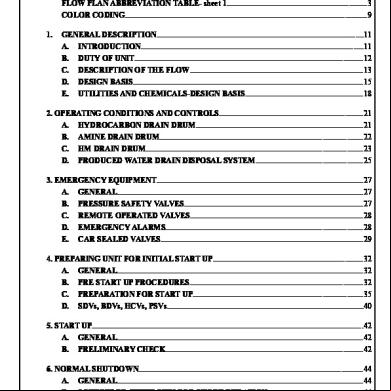
Closed Drain System 1v3u3e
November 2019 103
Sistem (closed System) 4e5vb
December 2020 0
Drain 3lk5k
April 2020 24
Intercostal Drain 234m38
March 2021 0
Delta Drain 1z5m1w
November 2019 55
Vertikal Drain y6kp
December 2020 0More Documents from "Marcel" y5hr

Pas-si-simple-by-yann-tiersen-from-amelie-soundtrack.pdf 1h2n2l
May 2021 0
Ludovico-einaudi.-elegy-for-the-arctic.pdf 54k6v
July 2022 0
Closed Drain System 1v3u3e
November 2019 103
2c82t
October 2019 206
Norsok U-001 Subsea Production System.pdf 733773
January 2022 0