Alluvial Soil 465m8
This document was ed by and they confirmed that they have the permission to share it. If you are author or own the copyright of this book, please report to us by using this report form. Report r6l17
Overview 4q3b3c
& View Alluvial Soil as PDF for free.
More details 26j3b
- Words: 12,488
- Pages: 36
Technical Supplement 14A
Soil Properties and Special Geotechnical Problems Related to Stream Stabilization Projects
(210–VI–NEH, August 2007)
Technical Supplement 14A
Soil Properties and Special Geotechnical Problems Related to Stream Stabilization Projects
Part 654 National Engineering Handbook
Issued August 2007
Cover photos: Top—Where streambanks are unstable, their drained and undrained conditions may need to be evaluated and tested, both onsite and in the laboratory.
Bottom—Geotechnical analysis begins with logging and sampling of the bank materials.
Advisory Note Techniques and approaches contained in this handbook are not all-inclusive, nor universally applicable. Deg stream restorations requires appropriate training and experience, especially to identify conditions where various approaches, tools, and techniques are most applicable, as well as their limitations for design. Note also that product names are included only to show type and availability and do not constitute endorsement for their specific use. (210–VI–NEH, August 2007)
Technical Supplement 14A
Contents
Soil Properties and Special Geotechnical Problems Related to Stream Stabilization Projects
Purpose
TS14A–1
Introduction
TS14A–1
Soil classification
TS14A–1
Soil shear strength
TS14A–3
Relatively permeable soils
TS14A–3
Soils with relatively low permeability
TS14A–3
Stiff, fissured clays
TS14A–3
Stability evaluations of bank slopes
TS14A–5
Evaluation of streambank characteristics contributing to streambank failure
TS14A–8
Typical slope instability problems and behavior of common soil types
TS14A–8
Solutions to typical slope instability problems
TS14A–9
Information required for slope stability evaluation of slopes TS14A–14
Sloughing and piping/sapping of streambanks TS14A–14 Recognizing the problem.............................................................................TS14A–19 Traditional solutions.....................................................................................TS14A–19 Soil bioengineering solutions to piping/sapping problems......................TS14A–20
Shallow slope failures in blocky structured (fissured) highly TS14A–20 plastic clays Predicting stable slopes in plastic clays....................................................TS14A–22 Analyses where the effective cohesion is significant...............................TS14A–23 Recognizing the problem.............................................................................TS14A–23 Soil bioengineering solutions to shallow slope failures in.......................TS14A–24 blocky clays Traditional solutions.....................................................................................TS14A–24
Dispersive clays TS14A–25 Recognizing the problem.............................................................................TS14A–25 Crumb test reactions....................................................................................TS14A–26 Soil bioengineering solutions to dispersive clay problems.....................TS14A–26 Traditional solutions.....................................................................................TS14A–26
(210–VI–NEH, August 2007)
TS14A–i
Technical Supplement 14A
Soil Properties and Special Geotechnical Problems Related to Stream Stabilization Projects
Low plasticity sands and silts TS14A–27 Analysis of slope stability in low plasticity sands and silts . ..................TS14A–27 Equations for analyzing infinite slope stability.........................................TS14A–30 Seepage parallel to slope.............................................................................TS14A–30 Horizontal seepage.......................................................................................TS14A–30
Tables
Table TS14A–1
Description of coarse-grain soil relative density TS14A–2
Table TS14A–2
Description of fine-grain soil consistency
TS14A–2
Table TS14A–3
Estimated soil properties
TS14A–4
Table TS14A–4
Table TS14A–5
Figures
Figure TS14A–1
Hand held torvane device
TS14A–2
Figure TS14A–2
Empirical correlation between effective phi angle (φ) and plasticity index (PI) from
TS14A–5
Estimated values for dry unity weight of sands
TS14A–27
Estimated values of relative density for described soils
TS14A–28
TS14A–ii
Part 654 National Engineering Handbook
triaxial tests on normally consolidated clays
Figure TS14A–3
Factor of safety computed before (a, FS = 1.107) TS14A–6 and after (b, FS = 0.99) erosion of toe of slope
Figure TS14A–4
Failed streambank in Tarboro, NC, following TS14A–7 high channel flows following Hurricane Floyd
Figure TS14A–5
Shallow sloughing failure in zone of saturated TS14A–9 sand
Figure TS14A–6
Typical slope stability failure in clay soil type
Figure TS14A–7
Before and after pictures of project, Tannehill TS14A–10 Branch Givens Park in Austin, TX
(210–VI–NEH, August 2007)
TS14A–9
Technical Supplement 14A
Soil Properties and Special Geotechnical Problems Related to Stream Stabilization Projects
Part 654 National Engineering Handbook
Figure TS14A–8
Before and after pictures of project, West TS14A–10 Bouldin Creek at South 6th Street in Austin, TX
Figure TS14A–9
Before and after pictures of project, Shoal Creek in Austin, TX
TS14A–11
Figure TS14A–10
Barb structures installed to protect toe of slope from erosion
TS14A–11
Figure TS14A–11
Sheet pile wall at toe of slope in Tarboro, NC TS14A–12
Figure TS14A–12
Gabion wall constructed at toe of slope TS14A–12 enables reconstruction of failed slope where right-of-way limitations prevented flattening of the upper slope and use of other conventional toe protection measures at the toe
Figure TS14A–13
Reinforced fill at toe of slope in Austin, TX
Figure TS14A–14 West Bouldin Creek at South 6th Street, TS14A–13 Austin project during last stages of construction
Figure TS14A–15 Other slope stabilization projects
Figure TS14A–16 Construction of a geotextile reinforced slope TS14A–16 with large derrick stone armoring at toe of slope
Figure TS14A–17 Sloughing of saturated low plasticity zone in TS14A–17 lower streambanks caused by seepage forces
Figure TS14A–18 Progression of sloughing type of failure mechanism in a streambank
TS14A–18
Figure TS14A–19 Slickensides in exposure of clay soil
TS14A–20
Figure TS14A–20 Stream slope that failed when the stream was TS14A–21 deepened to increase flow capacity
Figure TS14A–21 Progression of events that can result in bank TS14A–21 instability
Figure TS14A–22 Infinite slope equation for slope with small cohesion value
TS14A–23
Figure TS14A–23 Blocky structured clay in streambank expo- sure
TS14A–23
Figure TS14A–24 Photographs of exposure of dispersive clays TS14A–25 in side slopes of streams in TX and OK
Figure TS14A–25 Typical reactions in crumb test, a test for dispersive soils
(210–VI–NEH, August 2007)
TS14A–13
TS14A–14
TS14A–26
TS14A–iii
Technical Supplement 14A
TS14A–iv
Soil Properties and Special Geotechnical Problems Related to Stream Stabilization Projects
Part 654 National Engineering Handbook
Figure TS14A–26 A streambank where highly dispersive clays were treated by applying and mixing in hydrated lime to the slope soils
Figure TS14A–27 An example of a chart used to estimate TS14A–29 effective friction angles for different types of soils
(210–VI–NEH, August 2007)
TS14A–27
Technical Supplement 14A
Soil Properties and Special Geotechnical Problems Related to Stream Stabilization Projects
Purpose The purpose of this technical supplement is to describe special geotechnical problems related to stream stabilization projects. Topics addressed in this section include: • parameters used for classifying soils into engineering behavior groups • recognizing streambank instability and erosion problems that have geotechnical root causes • piping/sapping of streambanks • surficial failures in blocky-structured, highly plastic clays • severe erosion in dispersive clays • remedial methods for stabilizing slopes where oversteepening is a result of erosion of the toe of the slope
Introduction Soil bioengineering measures increase stream roughness and slow the water velocity near the slope face. They also armor and reinforce the surface soils. However, some problems with instability and excessive erosion of streambanks are not readily solved by soil bioengineering techniques alone. Problems involving rotational failures of streambanks, piping (sapping) of bank soils, and shallow slides in highly plastic soils are difficult to solve using only soil bioengineering techniques. Erosion on streambanks in highly dispersive clay soils also cannot be solved with soil bioengineering measures alone. If appropriate remedial solutions are to be designed, engineers and planners must recognize and understand special instability problems that have underlying geotechnical causes. Analyzing bank slopes for geotechnical stability requires an understanding of a complex system of forces. Evaluating how to protect the soils in the slopes from the erosive forces of flowing water acting against otherwise unprotected streambanks frequently is only part of the task. Even if banks are protected from the erosive forces of the water in the channel, external forces including seepage from the bank and gravity
acting on soils in the bank can induce slope failures. The forces involved in bank instability problems include gravity acting on the soils in the slope, the internal resistance of soils in the slope, seepage forces in the soils in the slope, as well as the tractive stresses imposed on the soils by flowing water. Deg various methods for streambank stabilization, such as retaining walls, reinforced fills, sheet piles, and others, requires specialized engineering experience and knowledge. Analytical methods require parameters that are either estimated from other soil properties or obtained in laboratory testing designed for obtaining them.
Soil classification The Unified Soil Classification System (USCS) is used to group soils based on similar engineering behavior. The USCS is described in two American Society for Testing and Materials International (ASTM) Standards. ASTM D2487 details classifying soils in the USCS using laboratory data. ASTM D2488 describes methods for estimating the classification of a soil from field tests. Classifying soils by the USCS requires data on the following parameters: • The percentage by dry weight of the total sample that is of three size categories: fines, sands, and gravels. The USCS only considers the portion of a deposit finer than 3 inches. Larger particles are described, but not included in classification procedures. A more detailed description of the three particle size groups is: – Percent fines is the percent of the sample finer than the #200 sieve. These particles are smaller than 0.075 millimeter. Particles finer than the #200 sieve include silt and clay size particles that are usually also evaluated with Atterberg limit tests described later in this section. Percent fines is one of the most important parameters in identifying soil types. – Percent sand is the percentage of the sample consisting of sand size particles, which are particles larger than the #200 sieve (0.075 mm) and smaller than gravel size particles described next (smaller than 4.76 mm).
(210–VI–NEH, August 2007)
TS14A–1
Technical Supplement 14A
Soil Properties and Special Geotechnical Problems Related to Stream Stabilization Projects
– Percent gravel size is the percentage of the total sample consisting of particles larger than 4.76 millimeters, but smaller than 3 inches. • Soils with 50 percent or more fines content and those coarse-grained soils with significant clay and silt content (more than 5% fines), are usually also evaluated by performing Atterberg limit tests on the portion of the sample smaller than a #40 sieve. Atterberg tests are useful in identifying the water holding and plasticity characteristics of those soils.
Figure TS14A–1
Table TS14A–1
Description of coarse-grain soil relative density Evaluation/description
Very loose
A ½-in-diameter rod can be pushed easily by hand into soil Soil can be excavated with a spade. A 2-in, square, wooden peg can easily be driven to a depth of 6 in Soil is easily penetrated with a ½-in rod driven with a 5-lb hammer Soil requires a pick for excavation. A 2-in, square, wooden peg is hard to drive to a depth of 6 in Soil is penetrated only a few cm with a ½-in rod driven with a 5-lb hammer
Medium dense Dense
Very dense
TS14A–2
The relative denseness or looseness of sandy and gravelly soils with few fines may be characterized with simple field tests such as the one described in table TS14A–1. The saturated consistency of fine-grained soils with significant plasticity (plasticity index greater than about 7) correlates well with the soils’ undrained shear strength. Saturated undrained strength of plastic finegrained soils may be estimated with a field torvane device such as the one shown in figure TS14A–1 or from the descriptions provided in table TS14A–2.
Hand held torvane device (Photo courtesy Geotest Instruments, Inc.)
Density description
Loose
Part 654 National Engineering Handbook
Table TS14A–2
Saturated consistency
Description of fine-grain soil consistency
Evaluation/description
Estimated undrained shear strength ( lb/ft2)
Very soft
Thumb will penetrate greater than 1 in. Soil is extruded between fingers
Soft
Thumb will penetrate about 250–500 1 in. Soil molded by light finger pressure
Medium
Thumb will penetrate about 500–1,000 ¼ in. Soil molded by strong finger pressure
Stiff
Indented with thumb
1,000–2,000
Very stiff
Indented by thumb nail
2,000–4,000
Hard
Thumbnail will not indent
>4,000
(210–VI–NEH, August 2007)
<250
Technical Supplement 14A
Soil Properties and Special Geotechnical Problems Related to Stream Stabilization Projects
Soil shear strength The shear strength of soils may vary depending on the rate that load is added to the soil, duration of the load, whether a previous load has been exerted on the soil (in particular for overconsolidated clays), and the permeability of the soil. Shear strength parameters are often characterized as undrained and drained parameters. The undrained and drained are not a description of the water level in the soils, but rather a description of the pore pressure condition in the soil when it is loaded. An undrained condition (also called short term, quick, total stress, or unconsolidatedundrained) assumes that pore pressures will develop due to a change in load. The assumption is that the pore pressures that develop are not known and must be implicitly considered in the methods used to test samples for this condition. A drained condition (also called long term, slow, effective stress, or consolidated-drained) implies that either no significant pore pressures are generated from the applied load or that the load is applied so slowly that the pressure dissipates during the slowly applied loading.
Relatively permeable soils Soils with a permeability of 1×10⁻⁴ centimeter per second or greater are often assumed to have a permeability rate high enough that excess pore pressures do not develop from loads applied at normal rates. Soils with these characteristics are generally in the following groups:
Part 654 National Engineering Handbook
tests. The drained shear strength applies to both shortterm and long-term load conditions. Estimated shear strength parameters for this category of soil types are shown in table TS14A–3.
Soils with relatively low permeability Soils with relatively low permeability (a coefficient of permeability less than about 1×10⁻⁴ cm/s) behave in a more complex manner. The shear strength of these soils varies depending on the rate of load application. Soils that are not in the categories described are usually in this group. If a soil has low permeability and experiences a fast change in load, undrained shear strength parameters are appropriate for analyses. After a load is maintained for a sufficient period of time, the pore pressures generated by the load application will dissipate. At that time, the soil will exhibit drained shear stress parameters. Analyses of fine-grain soils should consider both undrained and drained conditions, with the most critical condition governing the design. Typical soil properties for fine-grain materials are shown in table TS14A–3 (U.S. Army Corps of Engineers (USACE) 1994c, EM 1110–2–2504, Design of Sheet Pile Walls; Pile Buck Steel Sheet Piling Design Manual; and U.S. Navy, Naval Facilities Engineering Command (NAVFAC) DM–7.2, Foundations and Earth Structures). Peak effective phi (φ) angles for slowly permeable soils may be estimated with empirical charts such as shown in figure TS14A–2 (Hopkins, Allen, and Dean 1974; Kenny 1959; Bjerrum and Simons 1960).
• coarse-grain soils with less than 5 percent fines • coarse-grain soils with more than 5 percent fines, but with fines which have a plasticity index less than 8 • fine-grain soils with a plasticity index less than 5 The shear strength of this category of soils is measured using consolidated-drained (CD) or consolidated-undrained conditions with pore pressure measurements (CU´) shear tests. The shear strength of this group of soils may also be estimated from in situ tests such as standard penetration tests or cone penetration
Stiff, fissured clays Overconsolidated clay soils often contain fissures and slickensides. They behave differently than soils with similar plasticity, which do not have these features. Slope stability analyses and the design of sheet pile walls should consider the fully softened shear strength, which models the effect on shear strength of the network of discontinuities in the soil. If the slope or wall is designed to stabilize a recent slide, the residual shear strength should be considered. Both
(210–VI–NEH, August 2007)
TS14A–3
Estimated soil properties
Moist unit weight (lb/ft3)
Saturated unit weight (lb/ft3)
Loose sand
95–125
Medium dense sand Dense sand
Soil type
1/
Undrained shear strength properties
Drained shear strength properties
Angle of wall friction (steel pile), δ
Wall/soil adhesion 3/ (lb/ft2)
Angle of internal friction, φ
Cohesion (lb/ft2)
Angle of internal friction, φ
120–130
0
28
0
28
0.5xφ
0
110–130
125–135
0
32
0
32
0.5xφ
0
110–140
130–140
0
38
0
38
0.5xφ
0
Very soft clay
85–100
85–100
0–250
0
0
See note 2
0.5xφ
0–250
Soft clay
100–120
100–120
250–500
0
0
See note 2
0.5xφ
250–500
Medium clay
110–125
110–125
500–1,000
0
0
See note 2
0.5xφ
500–750
Stiff clay
115–130
115–130
1,000–2,000
0
50–100
See note 2
0.5xφ
750–950
Very stiff clay
120–140
120–140
2,000–4,000
0
100
See note 2
0.5xφ
950
Hard clay
>130
>130
>4,000
0
100
See note 2
0.5xφ
950
Notes: 1/ See tables TS14A–1 and TS14A–2 for qualitative descriptions of soil types. 2/ See figure TS14A–2. 3/ Wall/soil adhesion is typically 0 for drained (long-term) conditions.
Soil Properties and Special Geotechnical Problems Related to Stream Stabilization Projects
(210–VI–NEH, August 2007)
Cohesion (lb/ft2)
Technical Supplement 14A
TS14A–4
Table TS14A–3
Part 654 National Engineering Handbook
Technical Supplement 14A
Soil Properties and Special Geotechnical Problems Related to Stream Stabilization Projects
the fully softened phi angle and the residual phi angle of these soils are independent of the original strength of the clay and such factors as water content and liquidity index. The strength of these soil types seems to depend only on the size, shape, and mineralogical composition of the constituent particles and the effective normal stress (Stark and Hisham 1997). Fully softened phi angles are usually assumed to be in the range of 18 to 26 degrees and residual phi angles in the range of 6 to 18 degrees. This special type of soil is described further in the following sections with photographs and problems that are associated with the soil type.
the slope due to stream bed degradation, bank erosion, or toe erosion; and load added to the top of the streambank such as adding spoil. A slope is stable as long as the internal forces in the bank soils resisting failure exceed those causing failure. Computerized analyses are available to enable engineers to evaluate how changed conditions can impact this ratio of forces. The ratio of the resisting force to the causative or driving forces is usually termed the factor of safety of a slope.
Stability evaluations of bank slopes Stream channel banks can fail when conditions change that affect the stability of the slope. Examples of changes in conditions include changes in the potentiometric surface (water table) in the slope; changes in the slope configuration including increased height of
Figure TS14A–2
Part 654 National Engineering Handbook
FS =
∑ RESISTING Forces ∑ DRIVING Forces
Analyses compute these forces for assumed or known potential failure surfaces using parameters to represent soils in the slope and ground water conditions. If the factor of safety is greater than 1.0, a failure is not predicted. In existing failed slopes, analyses are conducted to determine what changes can be made to increase the factor of safety to a desirable value. A
Empirical correlation between effective phi angle (φ) and plasticity index (PI) from triaxial tests on normally consolidated clays
50 Kenney (1959) Bjerrum and Simons (1960) Ladd et al. (1977)
30
′
′
max
(degrees)
40
′at
20 Average (Bjerrum and Simons 1960) ±1 Standard deviation (U.S. Navy 1971)
10
0
0
10
20
30
40
50
60
70
80
90
100
Plasticity index, Pl (210–VI–NEH, August 2007)
TS14A–5
Technical Supplement 14A
Soil Properties and Special Geotechnical Problems Related to Stream Stabilization Projects
factor of safety of at least 1.3 is ordinarily considered desirable.
of streams, where the erosive attack at the toe of the slope is particularly severe. Figure TS14A–4 shows a slope where erosion of the toe has caused slope instability. In figure TS14A–4(a), the overall slope is seen with erosion that occurred at the toe of the slope following a large runoff event. Figure TS14A–4(b) shows the effect of the slope failure at the top of the slope, and figure TS14A–4(c) shows the middle of the failed slope area. Other ways that slope geometry or conditions may change, resulting in instability, include:
Resisting forces include the frictional resistance of soil particles along a potential failure surface, cohesive forces if the soil contains significant clay, and the ive resistance of the weight of soil at the toe of the slope, if the slope is not vertical. Driving forces that cause failure consist mainly of the gravity forces of the soil in the slope above the center of rotation, together with any seepage forces present. Conditions that may change in a stable slope to create instability were previously described.
• A change in the geometry of the slope may occur when the streambed lowers or degrades due to the instability of the stream system. The increased height of the slope and the oversteepening that occur may cause the factor of safety to be reduced to below 1.0.
An example of a change in slope geometry is removal of the toe of the slope by streamflow. This removal of soil at the toe of the slope reduces the gravity forces resisting failure and may cause the factor of safety of the slope to be reduced to less than 1.0. Slope failures normally occur when the factor of safety is less than 1.0. This type of change in the geometry of the slope is probably responsible for more slope stability failures in streambanks than any other single cause. Figure TS14A–3 shows a factor of safety computation for a simple example slope before and after toe erosion. The eroded toe of the slope reduces the forces resisting failure so that the computed factor of safety changes from 1.1 to less than 1.0, and a failure is predicted. Repeated occurrences are common in this scenario. After a slope failure occurs from erosion of the toe, the failed material at the bottom of the slope can be subsequently eroded and the process repeats itself, with the top width of the channel increasing at each occurrence. This process is common in curves
Figure TS14A–3 (a)
TS14A–6
Part 654 National Engineering Handbook
• A load may be added to the bank soils at the top of the slope. This additional load may be from construction or the additional weight of soil or rock spoil. This added load may increase the forces acting with gravity to cause a slope failure. Examples of added load are dikes added for flood protection.
• The potentiometric surface (water table) may become elevated in the bank soils after prolonged high rainfall events, changing moist soils to a saturated condition. Saturation usually substantially reduces the shear strength of soils and increases their weight. This may cause the factor of safety to become less than 1.0.
Factor of safety computed before and after erosion of toe of slope: (a) before, FS=1.107; (b) after, FS=0.99 (b)
(210–VI–NEH, August 2007)
Technical Supplement 14A
Figure TS14A–4
(a)
Soil Properties and Special Geotechnical Problems Related to Stream Stabilization Projects
Part 654 National Engineering Handbook
Failed streambank in Tarboro, NC, following high channel flows following Hurricane Floyd. Erosion of the toe caused bank instability in the slope. Measures to protect the toe of the slope are essential, in addition to assuring stability of the system. (b)
(c)
(210–VI–NEH, August 2007)
TS14A–7
Technical Supplement 14A
Soil Properties and Special Geotechnical Problems Related to Stream Stabilization Projects
• Soils in the bank may become saturated from prolonged storage of water in the stream channel. When the water level in the stream recedes, the saturated zone of soils may then have a reduced factor of safety from the increased weight of the soils and the resulting lower shear strength. This condition is sometimes termed a drawdown condition. Its severity is a function of the time that the water level remains high, charging the banks with infiltrated water; the permeability of the bank soils; and the rate at which drawdown occurs. Banks of high clay content soils are subject to failure and collapse under rapid drawdown after prolonged high flows.
• The nature of the soils in the slope may change over time. This may occur from weathering of minerals in the soil, development of a desiccated structure in clays, an opening of a slickensided structure from stress relief, and other causes. The phenomena of desiccated clays and how they affect the stability of streambanks is described in detail in the following sections.
Evaluation of streambank characteristics contributing to streambank failure NEH654.03 describes how geology, tectonic history, climate, surficial processes, and time determine the types of landscapes and streams. In many landscapes, the streams reflect a continuum of the same processes, such as downcutting, erosion, and sedimentation, over a long time period. Materials from certain geologic processes and landscape locations can have higher streambank stability than others. Glacial till and loess are more stable in streambanks than sediments deposited by other geomorphic processes such as materials deposited by braided steams. Peat, formed in a lake or marsh, may form a vertical streambank if the peat is not layered with other materials. A boulder or cobble streambed and streambank will be more stable than a stream in a finer textured material because of the higher resistance provided by the coarse textured material. TS14A–8
Part 654 National Engineering Handbook
The side slope (cotangent) of the streambank is an important factor in the probability of a potential failure. The steeper a streambank, the higher the probability of a slope failure occurring. The extreme condition is an overhanging slope. Overhanging conditions can only occur in streambank materials which have cementation, plant roots, or unusual temporary stabilizing forces such as capillary stresses. Overhanging slopes are inherently unstable and can fail with only slight changes in the bank conditions. Ground water flow emerging from the surface of a streambank contributes to reducing the stability of the streambank. This topic is described in more detail in a following section. Streambank height is often a reflection of stream type (Rosgen stream classification F and G channels versus E and C channels). The probability of streambank instability is inversely proportional to streambank height. If two streambanks of different heights have the same soil type, the higher streambank will have more potential for rotational failure. This is the condition reflected by the downcutting and widening in the channel evolution model (CEM) (Schumm, Harvey, and Watson 1981, 1984), Type III, where the critical bank height exceeds the stable bank height (hc > h). Density of roots in the streambank can also be a factor in streambank stability. The reinforcement of dense mats of roots may reduce the probability of some failures to occur. The effectiveness of the root mass reinforcement varies by plant species and whether the plants are alive or dead.
Typical slope instability problems and behavior of common soil types Bank instability problems and slope failures may have many shapes. Failures may appear shallow and only involve surficial sloughing. Some failures involve deep-seated rotational failures. Failures involving limited thin seams of weak soil may be wedge or block-shaped. The appearance of a slope failure often provides clues to the type of soil involved in the failure and possible contributing factors in the failure.
(210–VI–NEH, August 2007)
Technical Supplement 14A
Soil Properties and Special Geotechnical Problems Related to Stream Stabilization Projects
Figure TS14A–5 shows a shallow slide occurring from a zone of saturated sand sloughing from seepage forces. Figure TS14A–6 shows the results of a deep-seated rotational failure in clayey soils. A later section in the document describes this type of failure in detail. Sands and gravels in streambank slopes typically fail with a shallow sloughing type failure. These failures occur when the bank soils are subjected to oversteepening by toe erosion, or when subjected to seepage forces. The phenomenon of sapping refers to the sloughing of saturated zones of sand below the water table in the exposed streambanks. Slope failures in soils that have clay fines with significant plasticity typically have a circular appearance and are relatively deep-seated. These types of slides are usually precipitated by downcutting of the streambed. Slides of this type may be extensive and affect property some distance from the stream.
Solutions to typical slope instability problems
Part 654 National Engineering Handbook
remediate problems, using the same outline as above for the basic causes. One approach to prevent problems caused by erosion of the streambank toe is to protect it from attack by flowing water. A wide variety of methods can be used including: • riprap and other armoring techniques including cellular blocks and similar hard armor methods • soil bioengineering methods such as crib walls at the toe of the slope • realignment of the channel to reduce scour • barbs and other methods for deflecting flows away from the toe of the slope Figures TS14A–7, TS14A–8, and TS14A–9 show examples of methods used to protect the toe of slopes in a project in the city of Austin, Texas. Figure TS14A–10 shows the use of stream barbs to prevent erosion of the toe of a slope. Protecting the toe of a repaired slope from subsequent erosion is essential to the success of most streambank stabilization projects.
Instability in the side slopes of streambanks can be prevented or repaired after it occurs. The following outlines preventative methods and methods used to
Figure TS14A–5
Shallow sloughing failure in zone of saturated sand
Figure TS14A–6
(210–VI–NEH, August 2007)
Typical slope stability failure in clay soil type. Failure is a low-radius, deep rotational failure. (Photo credit City of Fargo, ND)
TS14A–9
Technical Supplement 14A
Figure TS14A–7 (a)
Figure TS14A–8
(a)
TS14A–10
Soil Properties and Special Geotechnical Problems Related to Stream Stabilization Projects
Part 654 National Engineering Handbook
Before and after pictures of project, Tannehill Branch Givens Park in Austin, TX. Note method for protecting toe of slope from erosion. (Photo courtesy of City of Austin, TX) (b)
Before and after pictures of project, West Bouldin Creek at South 6th Street in Austin, TX. Slope undercut and oversteepened by erosion of toe, which led to sloughing and bank failures. Note method for protecting toe of slope from erosion. (Photo courtesy of City of Austin, TX) (b)
(210–VI–NEH, August 2007)
Technical Supplement 14A
Figure TS14A–9
Soil Properties and Special Geotechnical Problems Related to Stream Stabilization Projects
Before and after pictures of project, Shoal Creek in Austin, TX. The toe of the slope was protected with riprap and the bank shaped above the protected toe. (Photo courtesy of City of Austin, TX)
(a)
Figure TS14A–10
Part 654 National Engineering Handbook
(b)
Barb structures installed to protect toe of slope from erosion
(210–VI–NEH, August 2007)
TS14A–11
Technical Supplement 14A
Soil Properties and Special Geotechnical Problems Related to Stream Stabilization Projects
Figure TS14A–11 shows a project where the toe of the slope was protected using both riprap and a sheet pile wall. In many circumstances, rigid boundary constraints, improvements, or other obstacles at the top of the slope do not allow the slope to be flattened. Consequently, constructing a vertical feature at the toe of the slope may be needed.
Figure TS14A–11
TS14A–12
Another way of reconstructing a slope where limited right of way occurs is the use of gabion baskets to protect the toe of the slope (fig. TS14A–12). Measures to increase the stability of slopes may include the use of geosynthetic reinforcement, which enables the slope to be reconstructed to a steeper
Sheet pile wall at toe of slope in Tarboro, NC. Vegetation will be established above wall. Note erosion control fabric.
(a)
Figure TS14A–12
Part 654 National Engineering Handbook
(b)
Gabion wall constructed at toe of slope enabled reconstruction of failed slope where right-of-way limitations prevented flattening of the upper slope and use of other conventional toe protection measures at the toe
(210–VI–NEH, August 2007)
Technical Supplement 14A
Soil Properties and Special Geotechnical Problems Related to Stream Stabilization Projects
Part 654 National Engineering Handbook
angle than would otherwise be possible. Examples of geosynthetic reinforcement include the use of geogrids and geocell products. These products are described in NEH654 TS14D. Figure TS14A–13 illustrates a project where the toe of the slope was protected by armoring, and the slope was reconstructed with reinforced soil lifts.
and beginning placement of geocell used to form the reinforced fill for the slope. Figure TS14A–13(b) shows the layers of geocell and gravel that were used to form the reconstructed slope. The geocell is a strong plastic honeycomb type of product that allows the slope to be rebuilt to a nearly vertical configuration at a much lower cost than a retaining wall.
Figure TS14A–13 shows the reconstruction of the slope at the West Bouldin Creek at South 6th Street project. Figure TS14A–13(a) shows the site in the initial stages of construction. The toe of the slope has been excavated in preparation for installing limestone boulder armor
Figure TS14A–14(a) shows the West Bouldin Creek at South 6th Street Austin project during last stages of construction, and figure TS14A–14(b) shows the project after completion of the backfill and establishment of vegetation. The use of soil in the filled geocells
Figure TS14A–13 (a)
Figure TS14A–14 (a)
Reinforced fill at toe of slope in Austin, TX. Note large stones used to protect reinforced fill from erosive forces in stream. (b)
West Bouldin Creek at South 6th Street, Austin, TX, project during last stages of construction (b)
(210–VI–NEH, August 2007)
TS14A–13
Technical Supplement 14A
Soil Properties and Special Geotechnical Problems Related to Stream Stabilization Projects
allows vegetation to grow and mask the construction. Geocells allow very steep slopes to be used in the reconstruction. These six photographs show a project to stabilize unstable streambanks at the Shoal Creek Project, City of Austin, Texas (fig. TS14A–15). Figure TS14A–15 shows other slope stabilization projects where reinforced fill protected by rock armor riprap placed at the toe of the slope were employed. Figure TS14A–15(e) shows geogrids, a heavy lattice of very strong plastic placed in layers in the granular fill used to reconstruct the slope. Figure TS14A–15(f) shows the completed project. Figure TS14A–16 shows construction of a geotextile reinforced slope with large derrick stone armoring at toe of slope. The reinforcement provided by the geotextile layers in the backfill allowed reconstructing the slope to a steep angle to accommodate a road at the top of the slope. The geotextile used was a heavy weight geosynthetic product that is anchored to the rock anchor wall and extends back into the granular backfill used to reconstruct the slope. The finished slope is vegetated and requires little maintenance. The rock toe wall is required to protect the fabric wrapped backfill from the abrasive forces of the water and debris in the channel. The cost of the rock toe wall is more than half the cost of the total project. Figure TS14A–16(a) shows the placement of the large rocks after the bottom lift of geosynthetic fabric and backfill have been placed. Figure TS14A–16(b) shows the geotextile wrapped over the rock toe wall, while the next layer of backfill is placed. The fabric will be folded from right to left over the layer of compacted fill to form a layer of reinforcement within the backfill. The use of geosynthetics in stream restoration is addressed in more detail in NEH654 TS14D.
Information required for slope stability evaluation of slopes Performing detailed slope stability evaluations is a highly specialized endeavor. Evaluations should be performed by personnel who are competent in the techniques of slope stability analysis and have the experience and tools to do the analyses. For analyses to be worthwhile, the shear strength parameters used in the analyses must be appropriate for the condiTS14A–14
Part 654 National Engineering Handbook
tions, and they must reflect the properties of the soils in the streambank. Soil properties may be estimated, but preferably, samples are obtained of representative horizons in the soil profile and tested in a geotechnical laboratory. Obtaining information on the soil horizons in a streambank from surface exposures may be helpful, but often, geotechnical investigations involving drill holes and sampling followed by laboratory testing may be needed. Often, correctly classifying the soil types in the bank, identifying the ground water conditions, and characterizing the condition of the soils provide most of the needed information for a preliminary evaluation of stability. Information on water table conditions may be gathered by hand auger holes that are left open for several days and monitored with a tape measure or other sounding device. More sophisticated measurements using observation wells installed along the stream may be useful for monitoring changes in water levels over a time period that involves several seasons. The following sections describe unique classes of commonly occurring slope stability problems that may be evaluated by methods that do not require computer analyses. When computerized analyses are required, specialists experienced in their use and application should be involved. The purpose of including discussions on these unique problems in this document is to enable field personnel to recognize these common situations and what remedial measures are appropriate.
Sloughing and piping/sapping of streambanks Slope failures can result where silts and sands with slight or no plasticity occur in the lower portion of a streambank. If horizons of this type of soil become saturated and seepage occurs at the streambank face, the soils can fail in several ways. In one mode of failure, particles may be detached and removed by the seepage exiting the bank. This can form an overhanging condition. The overhanging portion of the slope is prone to failure with any additional stress. The process by which these saturated silts and sands fail has been termed piping or sapping. For piping to occur, soils overlying the layer that is sloughing must
(210–VI–NEH, August 2007)
Technical Supplement 14A
Figure TS14A–15
Soil Properties and Special Geotechnical Problems Related to Stream Stabilization Projects
Part 654 National Engineering Handbook
Other slope stabilization projects
(a)
(b)
(c)
(d)
(e)
(f)
(210–VI–NEH, August 2007)
TS14A–15
Technical Supplement 14A
Soil Properties and Special Geotechnical Problems Related to Stream Stabilization Projects
Part 654 National Engineering Handbook
Figure TS14A–16 Construction of a geotextile reinforced slope with large derrick stone armoring at toe of slope (a)
(b)
(c)
(d)
TS14A–16
(210–VI–NEH, August 2007)
Technical Supplement 14A
Soil Properties and Special Geotechnical Problems Related to Stream Stabilization Projects
be able to form a roof. In a related mode of failure, the saturated bank in this zone of low plasticity soils slumps or sloughs under the seepage forces. Sloughing of the lower banks can undermine overlying zones that are stable on a steeper slope. Figure TS14A–17 shows sloughing in the lower saturated banks of an excavated stream. Piping/sapping failures and sloughing failures may occur quickly as the water table rises next to a stream or if excavation or degradation lowers the stream bottom. For instance, if a stream is degraded several feet by erosion and the lower banks of the stream consist of cohesionless sands with a high water table in the banks, a flow failure of the saturated sands usually occurs at almost the same time as the bed elevation is lowered. Sloughing of banks can also occur when flood storage in the stream saturates the banks, and the water level in the stream suddenly recedes. The saturated banks may fail in an infinite slope type of failure. Soil bioengineering methods usually cannot be established soon enough to prevent these types of failure. After a sapping failure has already occurred, soil bioengineering techniques may help to stabilize the toe area and prevent subsequent erosion of the toe. Protecting the toe of the slope from erosion and preventing future downcutting of the stream bottom are essential to minimizing future sapping problems.
Figure TS14A–17 Sloughing of saturated low plasticity zone in lower streambanks caused by seepage forces
Sapping in streambank caused by sloughing of saturated zone of silty sand below water table
Part 654 National Engineering Handbook
High ground water levels in the streambank soils may continue to cause bank sloughing, even if the toe is protected. The stability of slopes of low plasticity soils is analyzed using a set of equations that are termed infinite slope equations. Commonly, stable saturated slopes for low plasticity soils range from about 2.5H:1V to 3.5H:1V. Some stream slopes may be stable in these types of soils in a moist condition on slopes as steep as 1H:1V because the surface tension forces in moist sands and silts resist failure. If the soils in these steeper banks are subsequently saturated, sloughing of the soils can occur. Figure TS14A–18 illustrates the progression of this sloughing type of failure mechanism in a streambank. Figure TS14A–18(a) shows an initially stable condition, prior to stream degrading into a horizon of soils susceptible to sloughing and sapping/piping. Figure TS14A–18(b) illustrates how if the stream bottom degrades into an underlying horizon of low plasticity silty sands or silts, and a high ground water table exists, the seepage forces in the newly exposed sand horizon cause instability. Figure TS14A–18(c) shows that as further streamflows occur, the toppled blocks are eroded, and the sloughing process repeats itself. The top banks of the stream continue to recede unless the toe of the slope in the cohesionless soils is protected. Figure TS14A–18(d) shows the typical appearance of a slope where sloughing has occurred. Figure TS14A–18(e) shows the typical appearance of a slope where sloughing has occurred. Piping/sapping failures are most common in unconsolidated alluvium. Because alluvial soils are layered, cleaner lenses of sand or silt may occur between lenses of lower permeability clays. If seepage forces are concentrated in these cleaner soil lenses, the problem may be worse than it would be in a more homogeneous soil profile. When a horizon of saturated, cohesionless soil below the water table saps or flows from the slope, the lower part of the slope flattens and can cause an overhang in the uppermost soils in the streambank. These overlying soils then fail by toppling into the stream, as shown in figure TS14A–18(c). If erosion of the lower slopes is occurring or if the streambed is degrading, the process repeats. This results in substantial
(210–VI–NEH, August 2007)
TS14A–17
Technical Supplement 14A
Figure TS14A–18
Soil Properties and Special Geotechnical Problems Related to Stream Stabilization Projects
Part 654 National Engineering Handbook
Progression of sloughing type of failure mechanism in a streambank (b)
(a)
Original ground line
Cohesive horizon
Overhanging blocks topple into channel Cohesive horizon e
etric surfac
Potentiom
Potentiometric surface Failed slope ≈ 4H:1V
Cohesionless silt/sand horizon Cohesionless silt/sand horizon
Degraded channel bottom
(c)
(d) Original ground line
Soil eroded by channel
Toppled blocks
Possible future failures Cohesive horizon Potentiometric surface
Wet, beached slope
etric Potentiom surface
Channel bottom Cohesionless horizon
Cohesionless silt/sand horizon
Degraded channel bottom
(e)
TS14A–18
Cohesive horizon
(210–VI–NEH, August 2007)
Technical Supplement 14A
Soil Properties and Special Geotechnical Problems Related to Stream Stabilization Projects
widening of the stream top width. Soil bioengineering techniques may be effective in protecting the toe of these failed slopes from erosion, preventing subsequent failures. Piping/sapping problems are likely in a stream system that is degrading more quickly than the ground water level can lower by drainage where the bank soils are susceptible. If the streambank soils were able to drain at the same time the stream bottom degraded, the problem would not occur, because the streambanks would remain in a moist, rather than saturated condition. Piping/sapping failures may be initiated or accelerated by high rainfall, which recharges the water table in the streambank soils adjacent to the stream. Ground water flow may also be affected by nearby larger bodies of water. Ponding of water at the top of the streambank, especially where levees have been constructed, can also contribute to seepage pressures. Surface flow should be diverted and outletted into the stream away from a streambank area that is susceptible to this problem. Soil bioengineering methods alone are ineffective in addressing the seepage flow in permeable sand deposits because the flow quantities probably exceed the evapotranspiration ability of plants. This is one situation that will require granular filters in combination with a gravel/rock face to outlet the seepage and prevent piping of the bank and bed soils. Soil bioengineering may be integrated with granular filters to stabilize the upper banks and to reinforce the granular filter layers. Piping/sapping and sloughing may also occur when a stream has been full of water during a prolonged flood stage, and later the water in the stream lowers rapidly. The water in the stream stored during the higher stage may saturate sands and silts in the streambanks, and the saturated soils may fail by sloughing following the drawdown of the stream water. The likelihood of drawdown slope failures in a cohesionless soil horizon depends on how long the water is stored in the stream to saturate the slopes, how quickly the stream storage is emptied, and the permeability of the soil horizons in question.
Part 654 National Engineering Handbook
Recognizing the problem Recognizing a situation where piping/sapping has occurred or is occurring is easy if it is occurring at the time of the inspection. The shape of the streambanks and the appearance of soils in the banks are clues. The saturated zone at the toe of the streambank will be much flatter than the overlying horizons. Free water is visible as it exits the slope. Figure TS14A–17 illustrates the typical appearance of a streambank where sloughing has occurred. At the point where seepage emerges from the bank, the low plasticity soils that are saturated are on a very flat slope, usually in the range of 3H:1V to 4.5H:1V. The streambank is in a temporarily stable condition. The bank will likely remain stable at this condition, until the toe of the slope is again eroded, ground water levels rise, or the stream bottom degrades. If a piping/sapping failure is not active when it is inspected, recognizing the problem may be more difficult. Vegetation may have become established at the toe of the slope on the soils that have previously sloughed, obscuring clues of the earlier failure. For more information on diagnosis, see the articles by Hagerty (1991). Geologic and geotechnical investigations that determine whether these soil types occur in the streambanks, the elevations of seasonal high water tables, and other factors are important to recognize these potential problems.
Traditional solutions The most common method for solving piping/sapping problems is to use a layer of graded filter sand or sand/gravel mixture placed on the saturated zone of soil in the streambank. The filter material is designed to be more permeable than the bank soils, but fine enough to filter particles and prevent them from moving through the sand. The filter material is often protected from the erosive forces in the flowing stream with a layer of riprap, manufactured paving blocks, or other suitable methods. Usually, a geotextile separator is used between the filter layer and the overlying cover of riprap or paving blocks. This is described in more detail in NEH654 TS14K. Some designers use a geotextile placed directly on the bank, covered by riprap or other erosion resistant material, without placing a filter layer. This type of de-
(210–VI–NEH, August 2007)
TS14A–19
Technical Supplement 14A
Soil Properties and Special Geotechnical Problems Related to Stream Stabilization Projects
sign is usually less expensive, but may not be suitable for very fine silty soils. In a few situations, interceptor drains are installed away from the streambanks, parallel to the stream, to intercept ground water flow and prevent it from exiting at the slope face. Soil bioengineering methods may be effective in stabilizing a failed site if the conditions that caused the failure will most likely not recur with the same severity at that site.
Soil bioengineering solutions to piping/ sapping problems Soil bioengineering techniques are most useful in protecting lower silt/sand slopes after they have achieved a stable angle of repose. Soil bioengineering may also be effective in protecting upper cohesive soil horizons after the slopes have been shaped to a stable configuration. Soil bioengineering measures alone will not prevent a sapping/piping failure from occurring where conditions change rapidly to cause the failures. Soil bioengineering may be useful in transpiring excess water from streambanks, but vegetation will probably not be able to transpire the quantities of water available
Figure TS14A–19
TS14A–20
Part 654 National Engineering Handbook
from high ground water conditions in permeable soils or from the saturation of banks, which occurs during flood staging of the watercourse.
Shallow slope failures in blocky structured (fissured) highly plastic clays Highly plastic clays with a fissured or blocky structure can also cause severe stability problems in streambanks. The blocky structure of these soils results from desiccation that occurred after the soils were originally deposited. Repeated drying and wetting cycles cause a structure that is sometimes termed a slickensided structure. Figure TS14A–19 shows photographs of highly plastic clays with slickensides and blocky structure. Shallow surface slides commonly occur in these soils where streams have been modified or the stream system is not in equilibrium and bed degradation is occurring.
Slickensides in exposure of clay soil
(210–VI–NEH, August 2007)
Technical Supplement 14A
Soil Properties and Special Geotechnical Problems Related to Stream Stabilization Projects
Figure TS14A–20 shows a slope failure on a streambank that occurred when the stream was deepened about 4 feet to increase the flow capacity and blocky structured clays occurred in the streambanks. Root reinforcement of large trees was inadequate to resist the large forces active in this type of failure. Note that large trees were displaced by the failure. These types of failures have a shallow circular shape; are about 3 to 4 feet deep, measured normal to the slope surface; and frequently occur progressively. Larger failures follow small initial slides, if no corrective measures are taken. The scarp face (near-vertical surface at the top of the slide) may extend past the crest of the stream slope, but usually only after a series of failures has occurred at the same location. This type of slope failure often recurs if the failed material that has sloughed into the stream is eroded and the slope is again oversteepened. Protecting the toe area with soil bioengineering measures may reduce the severity of future failures, provided the streambed is not degrading. Because these plastic clays are seeking a stable slope that is usually very flat, the upper slope surfaces that remain after a failure must also be stabilized by flattening and using vegetation.
Part 654 National Engineering Handbook
The series of sketches in figure TS14A–21 show the progression of events that can result in bank instability. Figure TS14A–21(a) shows an initially stable condition prior to stream degrading into a horizon of soils that are susceptible to slope failures because of the blocky soil structure. Figure TS14A–21(b) shows streambed loss or degradation causes an effective steepening of the streamside slopes. The blocky structured clays are subject to slope failures when the stable condition is disturbed.
Figure TS14A–21
Progression of events that can result in bank instability
(a) H:1V
e4 Stabl
slope Blocky structure
(b) Figure TS14A–20
Stream slope that failed when the stream was deepened by about 4 feet to increase the flow capacity
Original slope Blocky structure Eroded soil Oversteepened slope (effective) Degraded channel bottom
(c) Future failures Failed soil mass
(210–VI–NEH, August 2007)
Scarp
TS14A–21
Technical Supplement 14A
Soil Properties and Special Geotechnical Problems Related to Stream Stabilization Projects
Terzaghi and Peck (1967) describe slope failures in excavated slopes in highly plastic clay soils as follows. Note that this description refers to excavations, but the same principles apply to a slope that is deepened or oversteepened either by human activities or degradation of the streambed. Almost every stiff clay is weakened by a network of hair cracks or slickensides. If the surface of weakness subdivides the clay into small fragments 1 inch or less in size, a slope may become unstable during construction or shortly thereafter. On the other hand, if the spacing of the ts is greater, failure may not occur until many years after the cut is made... If the spacing of the ts in a clay is greater than several inches, slopes may remain stable for many years or even decades after the cut is made. The lapse of time between the excavation of the cut and the failure of the slope indicates a gradual loss of the strength of the soil. Before excavation, the clay is very rigid, and the fissures are completely closed. The reduction of stress during excavation causes an expansion of the clay, and some of the fissures open. Water then enters and softens the clay ading these fissures. Unequal swelling produces new fissures until the larger chunks disintegrate, and the mass is transformed into a soft matrix containing hard cores. A slide occurs as soon as the shearing resistance of the weakened clay becomes too small to counteract the forces of gravity. Most slides of this type occur along toe circles involving a relatively shallow body of soil, because the shearing resistance of the clay increases rapidly with increasing distance below the exposed surface. The water seems to cause only the deterioration of the clay structure; seepage pressures appear to be of no consequence. After a slide occurs, the material underlying the newly exposed slide begins to soften, and the process continues until another slide occurs. The process does not stop until the slope angle becomes compatible with the softest consistency the clay can acquire… Thus the slopes become gentler...
TS14A–22
Part 654 National Engineering Handbook
In summary, shallow slope failures on streambanks composed of plastic clay soils are attributed to a network of fissures and blocky structures that develop due to alternating drying and wetting cycles. The desiccation of the clays may be recent, or it may have occurred long ago when the clays were originally deposited in an alluvial flood plain. Blocky structured clays may also occur very deep in older alluvial profiles and in glaciated areas. Instability is common after heavy rains or from elevated ground water. Water stored in the stream in a storm may be another source. The climatic regime in which these sites exist affects the severity of and time required to develop the fissured structure.
Predicting stable slopes in plastic clays A reliable analytical method for predicting a stable slope for highly plastic clays is not available. The most reliable method may be empirical examination of stable natural slopes in the same materials near the site. Nearby natural slopes that have not been significantly modified for at least 30 years should be studied. At one site studied by NRCS engineers, the cotangent of natural slopes was from 4H:1V to 7H:1V where the highly plastic clays were found. Failures occurred when the slopes were shaped to 3H:1V during enlargement of the stream cross section. The strength of highly plastic fissured soils for firsttime failures may be modeled using the fully softened condition as recommended by some authors including Stark and Hisham (1997). The fully softened strength of these soils depends primarily on the plasticity of the soils. These problems are most severe for CH soils with plasticity index (PI) values above 40. Soils with PIs greater than 80 are stable only on very flat slopes. Available laboratory testing techniques are inadequate to model the fissured structure in these soils. A conservative design assumes that the effective cohesion value in these blocky structured soils is zero, and the design is based only on the fully softened phi angle. The fully softened phi angle is independent of the original strength of the clay and such factors as water content and liquidity index (fig. TS14A–22). It seems to depend only on the size, shape, and mineralogical composition of the constituent particles and the effective normal stress (Stark and Hisham 1997). Fully softened phi angles are generally assumed to be in the range of 14 to 19 degrees. On this basis, clay soils
(210–VI–NEH, August 2007)
Technical Supplement 14A
Soil Properties and Special Geotechnical Problems Related to Stream Stabilization Projects
with PI values of about 30 to 40 are stable on slopes of about 3H:1V, while clays with high plasticity indices (greater than about 80) may require slopes as flat as 6.5H:1V for long-term stability.
Analyses where the effective cohesion is significant In silty, clayey, coarse-grained soils, a significant cohesion property may be present in effective stress parameters. For this assumption, computerized slope stability analyses can be used to calculate factors of safety by various methods such as the method of slices. These types of computer analyses are not appropriate for zero-cohesion soils because the critical failure surfaces are very shallow on the slope face with factors of safety approaching those obtained using the infinite slope equations. The equation for slightly cohesive sands with seepage parallel to the slope (eq. TS14A–1) is shown in figure TS14A–22, after an equation presented in Lambe and Whitman (1969): c × γ b z × cos 2 θ × tan ϕ FS = γ sat × H × sin θ cos θ
Figure TS14A–22
Part 654 National Engineering Handbook
Recognizing the problem This problem is identifiable by visual examination and textural evaluation of the soils in the streambanks. These failures occur usually in highly plastic soils classifying as CH, or fat clays, in the USCS. In the soil survey system of the NRCS, these soils are often classified as vertisols and are identified in the soil survey as having high shrink-swell potential. The most problematic soils have liquid limit values greater than 60 and PI values greater than 40. The severity of the problem is directly proportional to the liquid limit and plasticity index of the soils. The soils have an observable strongly blocky structure in an exposed face. The blocks of clay may be from one quarter to three-quarter inch in dimension. Figure TS14A–23 shows an exposure in a blocky clay soil. Other photographs show slickensides that are present in many such deposits. Slickensides develop from repeated wetting and drying cycles in clays.
(eq. TS14A–1)
Infinite slope equation for slope with small cohesion value
Figure TS14A–23
Blocky structured clay in streambank exposure
Soil with strength φ, unit weight γ b and γ sat
z
θ
(210–VI–NEH, August 2007)
TS14A–23
Technical Supplement 14A
Soil Properties and Special Geotechnical Problems Related to Stream Stabilization Projects
The failures usually occur in a progressive manner. The first evidence of a failure may be a small roll of soil at the toe of the slope. The final failure configuration is circular arc-shaped with a flat radius, and it encomes at least two-thirds of the slope length. The slides are usually no more than 3 or 4 feet deep, measured normal to the slope. Some slides may be deeper if previous sliding has occurred at the site, with depths normal to the slope of up to 8 feet. Slides are often triggered by a high-intensity rainfall event that closely follows a prolonged droughty period. Flood storage in the stream can also provide water to fill the cracks in the soil, causing failures when the stream empties. Streambanks seek their stable angle of repose. In a stable system, slopes on natural streams in these soil types reach a slope of from 4H:1V to 7H:1V, depending on the clay content and plasticity of the bank soils. Failures with highly plastic clay soils most often occur in streams modified by man or where streambed degradation has occurred, and the oversteepened slopes fail. These failures may not occur until many years following oversteepening of the streambanks.
Soil bioengineering solutions to shallow slope failures in blocky clays Soil bioengineering techniques that develop a root system capable of reinforcing the streambanks about 4 feet normal to the outer slope may provide added protection against these types of failures. A disadvantage is that transpiration from vegetation may aggravate the drying and shrinkage crack development of the soils. Litter and shade provided by vegetation may deter the drying of the clays from direct sunlight. The large forces that result from the weight of a saturated clay mass are difficult to overcome solely with root mass reinforcement. Some flattening of the slopes or replacement of the plastic clays with less plastic soils is required, in addition to soil bioengineering techniques, for these worst case situations. Vegetation may be effective in stabilizing the toe area of a failed slope, preventing it from being removed by subsequent erosion from flowing water in the stream. This allows stabilization of the upper slopes to be effective.
TS14A–24
Part 654 National Engineering Handbook
Soil bioengineering techniques, such as supplementing cribwalls with vegetation, brush layering, and similar measures, can be useful, but will probably only be long lasting if the more plastic clay soils are replaced behind the walls, and soils are shaped to a flat slope on the streambank above the reinforced structure.
Traditional solutions As with most problems related to slope instability, stabilizing the toe of the slope and ensuring that the stream grade will not degrade further are essential to the long-term success of any treatment of the problem. The most common methods for treating stream slopes in highly plastic clays that have failed may be summarized as follows: • Flattening the failed slope to a predicted stable slope is perhaps the most positive solution. This option requires considerable right-of-way if the slopes must be flattened significantly. For example, consider a 15-foot-deep stream that is on a slope of 3H:1V. If the slope needs to be flattened to about 5.5H:1V to be stable, the top width is increased by 37.5 feet. • Installing gravel trenches in the slope has been an effective treatment. The USACE used this type of repair successfully on a slope failure on the Sunflower River in Mississippi. Sills and Fleming (1992) describe a similar repair. This method is relatively economical, but has not been used widely, and designers may not be as confident in the results. • Another method of repairing these slides is covering the highly plastic soils in the slide area with soils having more favorable properties such as silty sands, gravels, or riprap. • Highly plastic clays may be modified by incorporating either hydrated or quick lime. About 5 percent by dry weight is added to the soils to treat them. This alternative is expensive because the lime is costly, and the construction procedures to apply and mix the lime into the streambanks are expensive.
(210–VI–NEH, August 2007)
Technical Supplement 14A
Soil Properties and Special Geotechnical Problems Related to Stream Stabilization Projects
Dispersive clays
Recognizing the problem
Dispersive clays are different in their chemical composition than ordinary, erosion-resistant clays. Dispersive clay soils are far more erodible than ordinary clays because the interparticle attraction is much reduced by imbalanced electro-chemical bonds. Streamside slopes in dispersive clay deposits often develop a highly rilled appearance, also showing a phenomenon referred to as jugging. Dispersive clays are described in detail in Soil Mechanics Note 13, Dispersive Clays.
Figure TS14A–24 (a)
Part 654 National Engineering Handbook
Dispersive clay slopes often are severely rilled. These rills often develop in a short time. Jugholes are an ideal diagnostic tool for dispersive clays. These features develop when a drying crack in the exposed soil provides an entrance for precipitation that can then erode the sides of the wall. This internal erosion of the crack results in subterranean cavities often termed jugholes. Figure TS14A–24 illustrates the special appearance of dispersive clays.
Photographs of exposure of dispersive clays in streamside slopes in TX and OK (b)
(c)
(210–VI–NEH, August 2007)
TS14A–25
Technical Supplement 14A
Soil Properties and Special Geotechnical Problems Related to Stream Stabilization Projects
Another diagnostic tool is that vegetation has little effect on the severity of the erosion of dispersive clays. Vegetation is less effective in reducing erosion on dispersive clays because the particles that are eroding are colloidal in size. They are much too fine to filter with vegetation, and they can go into suspension in essentially standing water. An excellent field test for dispersion is the crumb test. ASTM Standard Test Method D6572 covers methods for performing the test. The test requires a minimum of equipment and is excellent for screening purposes to determine if dispersive clays are likely present.
Crumb test reactions A common field test for dispersive clays is the crumb test, a test for dispersive soils (fig TS14A–25). A small clump of the soil (about a half-inch cube) is placed in a cocktail glass that has about an inch of distilled water, and observed for at least an hour. A rapid formation of a cloud around the soil indicates that it is dispersive. The observed reaction is typically given a rating from the criteria listed. 1—No reaction, water in glass remains clear. Ignore any slaking of clod; examine only for turbidity. 2—Cloud immediately around clod. A hint of a cloud occurs very near the clod. However, it does not spread significantly away from the clod.
Figure TS14A–25
TS14A–26
Part 654 National Engineering Handbook
3—A colloidal cloud spreads a considerable distance from the clod. However, it does not spread completely to meet the opposite side of the glass. 4—Cloud spreads around bottom and may cover bottom. The colloidal cloud may be so extensive that the whole bottom of the glass is covered. Reactions 3 and 4 are a very positive indicator of dispersive soil.
Soil bioengineering solutions to dispersive clay problems Soil bioengineering techniques are not likely to be effective in preventing or curing dispersive clay erosion problems on stream slopes. Severe erosion has been observed on the best vegetated sites.
Traditional solutions Several repair or preventive design measures have successfully been applied to dispersive clay sites. In the first method, the dispersive clays are covered with an insulating blanket to prevent the cracking of the clays that leads to more severe erosion. Blankets of sand/gravel/silts have been used with success. For silty sand or gravel blankets, the fines in the sand or gravel should be checked to assure they are not dispersive.
Typical reactions in crumb test, a test for dispersive soils
(210–VI–NEH, August 2007)
Technical Supplement 14A
Soil Properties and Special Geotechnical Problems Related to Stream Stabilization Projects
Part 654 National Engineering Handbook
Another method for treating dispersive clays is to chemically alter the soils. Dispersive clays are predominated by sodium, and replacing the sodium ions with calcium, magnesium, or aluminum ions improves the interparticle attraction of the clays. Chemicals that have been successfully used include hydrated lime (fig. TS14A–26), quick lime, fly ash, alum, and gypsum. Refer to Soil Mechanics Note 13 for more detailed information.
in susceptible soil types is studied by computing a factor of safety. Designers always prefer that the factor of safety for this type of analysis be greater than 1.1.
Low plasticity sands and silts
Unit weights The equations for computing factors of safety for infinite slope stability consider several possible conditions for a soil. Soil horizons above the water table are in a moist condition. The moist unit weight is computed as:
The problems of bank sloughing in low plasticity sands and silts with a high ground water table were described previously in this chapter. This section provides additional description of the problem and analytical tools.
Analysis of slope stability in low plasticity sands and silts A slope, such as the banks of a stream composed of sandy or silty soils with a low clay content, may slough if it is too steep. The slope that is stable for a given soil is studied with several equations termed infinite slope equations. The equations will be addressed in detail in the following sections. The stability of a stream slope
Figure TS14A–26
A streambank where highly dispersive clays were treated by applying and mixing in hydrated lime to the slope soils
Three equations are used to compute the factor of safety of the slope for three different assumed ground water flow conditions. The factor of safety of a slope depends on the following three factors: unit weights of soil and water, effective friction angle (phi angle), and the direction of seepage forces.
a. Moist unit weight. A moist unit weight value is computed using equation TS14A–2: w(%) γ moist = γ dry × 1 + 100
(eq. TS14A–2)
The moist unit weight of soils requires an estimate or measurement of the soil’s dry density and natural water content. In the absence of measurements, the dry unit weight of sands can be estimated from table TS14A–4. The natural water content depends on the climatic regime, antecedent rainfall, and many other environmental factors. For most sands, the natural water content of moist soils is in the range of 8 to 20 percent.
Table TS14A–4
Estimated values for dry unit weight of sands
Relative density of sand
γd – Dry density
Loose Medium Dense
90 105 115
(210–VI–NEH, August 2007)
(assumed), lb/ft3
TS14A–27
Technical Supplement 14A
Soil Properties and Special Geotechnical Problems Related to Stream Stabilization Projects
Example: Assume that it has been determined that the sands in a streambank horizon are loose in relative density, and the natural water content is about 12 percent. From table TS14A– 4, one can assume that the soils have a dry unit weight of about 90 pounds per cubic foot. Compute the moist unit weight of the sand (eq. TS14A–3). b. Buoyant unit weight. Several equations used to evaluate the stability for the infinite slope condition require a value for the buoyant unit weight of the soil. The buoyant unit weight is also called the submerged unit weight. Two parameters are used. First, the dry density of the soil is needed. It may be estimated from table TS14A–4 whether the approximate relative density is known. The second term needed is the specific gravity of the soil particles. The value for Gs is usually assumed to be 2.65 for most sands. This is the specific gravity of quartz, the predominant constituent of many sands. The buoyant unit weight of soil is computed using equation TS14A–4. γ moist = γ dry
plus the unit weight of water, 62.4 pounds per cubic foot in the United States system of measurement. For the previous example, the soil would have a saturated unit weight of 60.7+62.4 = 123.1 pounds per cubic foot.
Effective phi angle The other parameter used in these equations is the effective friction angle, also called the effective phi parameter, of the soil in the bank. The value may be estimated or measured in laboratory tests. The value generally varies from about 28 degrees to 40 degrees, depending on the relative density of the sand or silt. Table TS14A–5 may be used to estimate a numerical value for relative density from a narrative description. Example: Assume that the soils in the streambank are loose silty sands. From table TS14A–5, estimate a relative density value of 30 percent. From figure TS14A–27 (NAVFAC 1986), read an effective friction angle for a silty sand with a relative density of 30 percent to be 27.5 degrees.
Direction of seepage forces Three conditions are possible and are described in following sections.
w(%) × 1 + 100
12 = 90.0 lb/ft 3 × 1 + 100
Part 654 National Engineering Handbook
(eq. TS14A–3)
= 90 lb/ft 3 × 1.12 = 100.8 lb/ft 3
γ buoyant =
Gs − 1 × γ dry Gs
(eq. TS14A–4)
Example: Assume that it is determined that the sands in a stream horizon are loose to medium in relative density, and the specific gravity of the sand is 2.65. From table TS14A–4, assume the soils have a dry unit weight of about 97.5 pounds per cubic foot. Compute the buoyant unit weight of the sand (eq. TS14A–5): G −1 2.65 − 1 γ buoyant = s × γ dry = × 97.5 lb/ft 3 = 60.7 lb/ft 3 Gs 2.65 (eq. TS14A–5) c. Saturated unit weight. The saturated unit weight of soil is simply the buoyant unit weight
TS14A–28
Table TS14A–5
Estimated values of relative density for described soils
Relative density description
Numerical value of relative density
Very loose Loose Medium Dense Very dense
<15 15–35 35–65 65–85 >85
(210–VI–NEH, August 2007)
Technical Supplement 14A
Figure TS14A–27
Soil Properties and Special Geotechnical Problems Related to Stream Stabilization Projects
Part 654 National Engineering Handbook
An example of a chart used to estimate effective friction angles for different types of soils Angle of internal friction vs. density (for coarse-grained soils)
Angle of internal friction φ′ (degrees)
45
sity
en ve d
ati
40
Rel
%
100
75% GW
GP SW
35 ML 30
50%
SM and SP 25% range In this
φ′ Obtained from effective stress failure envelopes Approximate correlation is for cohesionless material without plastic fines
0 25
20
75
80
90
100
Material type
110
120
130
140
150
3
Dry unit weight (γd, lb/ft ) 1.2 1.1 1.0 0.9 0.8 0.75 0.7 0.65 0.6 0.55 0.5 0.45 0.4 0.35 0.3 0.25 0.2 0.15 Void ratio (e) 0.55
0.5
0.45
0.4
0.35 0.3 Porosity (n)
0.25
0.2
(210–VI–NEH, August 2007)
0.15
TS14A–29
Technical Supplement 14A
Soil Properties and Special Geotechnical Problems Related to Stream Stabilization Projects
Equations for analyzing infinite slope stability A separate equation is used for each of the three following seepage conditions: • no seepage • seepage flowing generally parallel to slope • seepage generally following horizontal flow paths The equation for no seepage is used to study the stability of soils above the water table. The condition where seepage generally follows horizontal flow paths is probably the one to use for most alluvial deposits because the layering of the alluvial soil profile creates this type of preferential flow path. Assume parallel flow paths for soils without much layering. Because the assumption for this analysis is that the soils have zero cohesion, the height of the slope is not a factor. The same factor of safety is calculated for any height of slope. A factor of safety of 1.1 is commonly regarded as acceptable for this condition because the failures are shallow sloughing types of failures and not usually disastrous in nature.
Moist slope equation If no seepage is exiting the slope face being examined, the factor of safety for that slope is simply stated as: FS = m × tan (φ ′ )
(eq. TS14A–6)
where: m = slope cotangent φ′ = internal friction angle of cohesionless slope soil Consider the example for 3H:1V permeability side slopes and soils with an effective φ′ angle of 26 degrees, the calculated factor of safety is:
TS14A–30
FS = 3 × tan ( 26 ) FS = 1.46
Part 654 National Engineering Handbook
Seepage parallel to slope When seepage exits the slope face and the direction of the flow is parallel to the slope face, equations TS14A–7 and TS14A–8 are applicable. This pattern of seepage occurs in very homogeneous soils with little or no horizontal layering. This assumption is typically not used to represent soil that has been compacted in layers or in alluvial soils. The equations are:
FS =
γ b × tan (φ ′ )
γ sat × tan (θ )
(eq. TS14A–7)
or
FS = m ×
γb × tan (φ ′ ) γ sat
(eq. TS14A–8)
where: θ = slope angle m = slope cotangent = cot (θ) γb = buoyant unit weight γsat = saturated unit weight φ′ = effective friction angle
Horizontal seepage Equations TS14A–9 and TS14A–10 assume that the seepage forces acting on the soils in the slope are due to flow along horizontal planes.
FS =
(γ
sat
)
× cos 2 (θ ) − γ w × tan (φ ′ ) (eq. TS14A–9) γ sat × sin (θ ) × cos (θ )
or
FS =
(γ
b
)
× m 2 − γ w × tan (φ ′ ) m × γ sat
where: θ = slope angle m = slope cotangent = cot (θ) γb = buoyant unit weight γsat = saturated unit weight φ′ = effective friction angle
(210–VI–NEH, August 2007)
(eq. TS14A–10)
Soil Properties and Special Geotechnical Problems Related to Stream Stabilization Projects
(210–VI–NEH, August 2007)
Technical Supplement 14A
Soil Properties and Special Geotechnical Problems Related to Stream Stabilization Projects
Part 654 National Engineering Handbook
Issued August 2007
Cover photos: Top—Where streambanks are unstable, their drained and undrained conditions may need to be evaluated and tested, both onsite and in the laboratory.
Bottom—Geotechnical analysis begins with logging and sampling of the bank materials.
Advisory Note Techniques and approaches contained in this handbook are not all-inclusive, nor universally applicable. Deg stream restorations requires appropriate training and experience, especially to identify conditions where various approaches, tools, and techniques are most applicable, as well as their limitations for design. Note also that product names are included only to show type and availability and do not constitute endorsement for their specific use. (210–VI–NEH, August 2007)
Technical Supplement 14A
Contents
Soil Properties and Special Geotechnical Problems Related to Stream Stabilization Projects
Purpose
TS14A–1
Introduction
TS14A–1
Soil classification
TS14A–1
Soil shear strength
TS14A–3
Relatively permeable soils
TS14A–3
Soils with relatively low permeability
TS14A–3
Stiff, fissured clays
TS14A–3
Stability evaluations of bank slopes
TS14A–5
Evaluation of streambank characteristics contributing to streambank failure
TS14A–8
Typical slope instability problems and behavior of common soil types
TS14A–8
Solutions to typical slope instability problems
TS14A–9
Information required for slope stability evaluation of slopes TS14A–14
Sloughing and piping/sapping of streambanks TS14A–14 Recognizing the problem.............................................................................TS14A–19 Traditional solutions.....................................................................................TS14A–19 Soil bioengineering solutions to piping/sapping problems......................TS14A–20
Shallow slope failures in blocky structured (fissured) highly TS14A–20 plastic clays Predicting stable slopes in plastic clays....................................................TS14A–22 Analyses where the effective cohesion is significant...............................TS14A–23 Recognizing the problem.............................................................................TS14A–23 Soil bioengineering solutions to shallow slope failures in.......................TS14A–24 blocky clays Traditional solutions.....................................................................................TS14A–24
Dispersive clays TS14A–25 Recognizing the problem.............................................................................TS14A–25 Crumb test reactions....................................................................................TS14A–26 Soil bioengineering solutions to dispersive clay problems.....................TS14A–26 Traditional solutions.....................................................................................TS14A–26
(210–VI–NEH, August 2007)
TS14A–i
Technical Supplement 14A
Soil Properties and Special Geotechnical Problems Related to Stream Stabilization Projects
Low plasticity sands and silts TS14A–27 Analysis of slope stability in low plasticity sands and silts . ..................TS14A–27 Equations for analyzing infinite slope stability.........................................TS14A–30 Seepage parallel to slope.............................................................................TS14A–30 Horizontal seepage.......................................................................................TS14A–30
Tables
Table TS14A–1
Description of coarse-grain soil relative density TS14A–2
Table TS14A–2
Description of fine-grain soil consistency
TS14A–2
Table TS14A–3
Estimated soil properties
TS14A–4
Table TS14A–4
Table TS14A–5
Figures
Figure TS14A–1
Hand held torvane device
TS14A–2
Figure TS14A–2
Empirical correlation between effective phi angle (φ) and plasticity index (PI) from
TS14A–5
Estimated values for dry unity weight of sands
TS14A–27
Estimated values of relative density for described soils
TS14A–28
TS14A–ii
Part 654 National Engineering Handbook
triaxial tests on normally consolidated clays
Figure TS14A–3
Factor of safety computed before (a, FS = 1.107) TS14A–6 and after (b, FS = 0.99) erosion of toe of slope
Figure TS14A–4
Failed streambank in Tarboro, NC, following TS14A–7 high channel flows following Hurricane Floyd
Figure TS14A–5
Shallow sloughing failure in zone of saturated TS14A–9 sand
Figure TS14A–6
Typical slope stability failure in clay soil type
Figure TS14A–7
Before and after pictures of project, Tannehill TS14A–10 Branch Givens Park in Austin, TX
(210–VI–NEH, August 2007)
TS14A–9
Technical Supplement 14A
Soil Properties and Special Geotechnical Problems Related to Stream Stabilization Projects
Part 654 National Engineering Handbook
Figure TS14A–8
Before and after pictures of project, West TS14A–10 Bouldin Creek at South 6th Street in Austin, TX
Figure TS14A–9
Before and after pictures of project, Shoal Creek in Austin, TX
TS14A–11
Figure TS14A–10
Barb structures installed to protect toe of slope from erosion
TS14A–11
Figure TS14A–11
Sheet pile wall at toe of slope in Tarboro, NC TS14A–12
Figure TS14A–12
Gabion wall constructed at toe of slope TS14A–12 enables reconstruction of failed slope where right-of-way limitations prevented flattening of the upper slope and use of other conventional toe protection measures at the toe
Figure TS14A–13
Reinforced fill at toe of slope in Austin, TX
Figure TS14A–14 West Bouldin Creek at South 6th Street, TS14A–13 Austin project during last stages of construction
Figure TS14A–15 Other slope stabilization projects
Figure TS14A–16 Construction of a geotextile reinforced slope TS14A–16 with large derrick stone armoring at toe of slope
Figure TS14A–17 Sloughing of saturated low plasticity zone in TS14A–17 lower streambanks caused by seepage forces
Figure TS14A–18 Progression of sloughing type of failure mechanism in a streambank
TS14A–18
Figure TS14A–19 Slickensides in exposure of clay soil
TS14A–20
Figure TS14A–20 Stream slope that failed when the stream was TS14A–21 deepened to increase flow capacity
Figure TS14A–21 Progression of events that can result in bank TS14A–21 instability
Figure TS14A–22 Infinite slope equation for slope with small cohesion value
TS14A–23
Figure TS14A–23 Blocky structured clay in streambank expo- sure
TS14A–23
Figure TS14A–24 Photographs of exposure of dispersive clays TS14A–25 in side slopes of streams in TX and OK
Figure TS14A–25 Typical reactions in crumb test, a test for dispersive soils
(210–VI–NEH, August 2007)
TS14A–13
TS14A–14
TS14A–26
TS14A–iii
Technical Supplement 14A
TS14A–iv
Soil Properties and Special Geotechnical Problems Related to Stream Stabilization Projects
Part 654 National Engineering Handbook
Figure TS14A–26 A streambank where highly dispersive clays were treated by applying and mixing in hydrated lime to the slope soils
Figure TS14A–27 An example of a chart used to estimate TS14A–29 effective friction angles for different types of soils
(210–VI–NEH, August 2007)
TS14A–27
Technical Supplement 14A
Soil Properties and Special Geotechnical Problems Related to Stream Stabilization Projects
Purpose The purpose of this technical supplement is to describe special geotechnical problems related to stream stabilization projects. Topics addressed in this section include: • parameters used for classifying soils into engineering behavior groups • recognizing streambank instability and erosion problems that have geotechnical root causes • piping/sapping of streambanks • surficial failures in blocky-structured, highly plastic clays • severe erosion in dispersive clays • remedial methods for stabilizing slopes where oversteepening is a result of erosion of the toe of the slope
Introduction Soil bioengineering measures increase stream roughness and slow the water velocity near the slope face. They also armor and reinforce the surface soils. However, some problems with instability and excessive erosion of streambanks are not readily solved by soil bioengineering techniques alone. Problems involving rotational failures of streambanks, piping (sapping) of bank soils, and shallow slides in highly plastic soils are difficult to solve using only soil bioengineering techniques. Erosion on streambanks in highly dispersive clay soils also cannot be solved with soil bioengineering measures alone. If appropriate remedial solutions are to be designed, engineers and planners must recognize and understand special instability problems that have underlying geotechnical causes. Analyzing bank slopes for geotechnical stability requires an understanding of a complex system of forces. Evaluating how to protect the soils in the slopes from the erosive forces of flowing water acting against otherwise unprotected streambanks frequently is only part of the task. Even if banks are protected from the erosive forces of the water in the channel, external forces including seepage from the bank and gravity
acting on soils in the bank can induce slope failures. The forces involved in bank instability problems include gravity acting on the soils in the slope, the internal resistance of soils in the slope, seepage forces in the soils in the slope, as well as the tractive stresses imposed on the soils by flowing water. Deg various methods for streambank stabilization, such as retaining walls, reinforced fills, sheet piles, and others, requires specialized engineering experience and knowledge. Analytical methods require parameters that are either estimated from other soil properties or obtained in laboratory testing designed for obtaining them.
Soil classification The Unified Soil Classification System (USCS) is used to group soils based on similar engineering behavior. The USCS is described in two American Society for Testing and Materials International (ASTM) Standards. ASTM D2487 details classifying soils in the USCS using laboratory data. ASTM D2488 describes methods for estimating the classification of a soil from field tests. Classifying soils by the USCS requires data on the following parameters: • The percentage by dry weight of the total sample that is of three size categories: fines, sands, and gravels. The USCS only considers the portion of a deposit finer than 3 inches. Larger particles are described, but not included in classification procedures. A more detailed description of the three particle size groups is: – Percent fines is the percent of the sample finer than the #200 sieve. These particles are smaller than 0.075 millimeter. Particles finer than the #200 sieve include silt and clay size particles that are usually also evaluated with Atterberg limit tests described later in this section. Percent fines is one of the most important parameters in identifying soil types. – Percent sand is the percentage of the sample consisting of sand size particles, which are particles larger than the #200 sieve (0.075 mm) and smaller than gravel size particles described next (smaller than 4.76 mm).
(210–VI–NEH, August 2007)
TS14A–1
Technical Supplement 14A
Soil Properties and Special Geotechnical Problems Related to Stream Stabilization Projects
– Percent gravel size is the percentage of the total sample consisting of particles larger than 4.76 millimeters, but smaller than 3 inches. • Soils with 50 percent or more fines content and those coarse-grained soils with significant clay and silt content (more than 5% fines), are usually also evaluated by performing Atterberg limit tests on the portion of the sample smaller than a #40 sieve. Atterberg tests are useful in identifying the water holding and plasticity characteristics of those soils.
Figure TS14A–1
Table TS14A–1
Description of coarse-grain soil relative density Evaluation/description
Very loose
A ½-in-diameter rod can be pushed easily by hand into soil Soil can be excavated with a spade. A 2-in, square, wooden peg can easily be driven to a depth of 6 in Soil is easily penetrated with a ½-in rod driven with a 5-lb hammer Soil requires a pick for excavation. A 2-in, square, wooden peg is hard to drive to a depth of 6 in Soil is penetrated only a few cm with a ½-in rod driven with a 5-lb hammer
Medium dense Dense
Very dense
TS14A–2
The relative denseness or looseness of sandy and gravelly soils with few fines may be characterized with simple field tests such as the one described in table TS14A–1. The saturated consistency of fine-grained soils with significant plasticity (plasticity index greater than about 7) correlates well with the soils’ undrained shear strength. Saturated undrained strength of plastic finegrained soils may be estimated with a field torvane device such as the one shown in figure TS14A–1 or from the descriptions provided in table TS14A–2.
Hand held torvane device (Photo courtesy Geotest Instruments, Inc.)
Density description
Loose
Part 654 National Engineering Handbook
Table TS14A–2
Saturated consistency
Description of fine-grain soil consistency
Evaluation/description
Estimated undrained shear strength ( lb/ft2)
Very soft
Thumb will penetrate greater than 1 in. Soil is extruded between fingers
Soft
Thumb will penetrate about 250–500 1 in. Soil molded by light finger pressure
Medium
Thumb will penetrate about 500–1,000 ¼ in. Soil molded by strong finger pressure
Stiff
Indented with thumb
1,000–2,000
Very stiff
Indented by thumb nail
2,000–4,000
Hard
Thumbnail will not indent
>4,000
(210–VI–NEH, August 2007)
<250
Technical Supplement 14A
Soil Properties and Special Geotechnical Problems Related to Stream Stabilization Projects
Soil shear strength The shear strength of soils may vary depending on the rate that load is added to the soil, duration of the load, whether a previous load has been exerted on the soil (in particular for overconsolidated clays), and the permeability of the soil. Shear strength parameters are often characterized as undrained and drained parameters. The undrained and drained are not a description of the water level in the soils, but rather a description of the pore pressure condition in the soil when it is loaded. An undrained condition (also called short term, quick, total stress, or unconsolidatedundrained) assumes that pore pressures will develop due to a change in load. The assumption is that the pore pressures that develop are not known and must be implicitly considered in the methods used to test samples for this condition. A drained condition (also called long term, slow, effective stress, or consolidated-drained) implies that either no significant pore pressures are generated from the applied load or that the load is applied so slowly that the pressure dissipates during the slowly applied loading.
Relatively permeable soils Soils with a permeability of 1×10⁻⁴ centimeter per second or greater are often assumed to have a permeability rate high enough that excess pore pressures do not develop from loads applied at normal rates. Soils with these characteristics are generally in the following groups:
Part 654 National Engineering Handbook
tests. The drained shear strength applies to both shortterm and long-term load conditions. Estimated shear strength parameters for this category of soil types are shown in table TS14A–3.
Soils with relatively low permeability Soils with relatively low permeability (a coefficient of permeability less than about 1×10⁻⁴ cm/s) behave in a more complex manner. The shear strength of these soils varies depending on the rate of load application. Soils that are not in the categories described are usually in this group. If a soil has low permeability and experiences a fast change in load, undrained shear strength parameters are appropriate for analyses. After a load is maintained for a sufficient period of time, the pore pressures generated by the load application will dissipate. At that time, the soil will exhibit drained shear stress parameters. Analyses of fine-grain soils should consider both undrained and drained conditions, with the most critical condition governing the design. Typical soil properties for fine-grain materials are shown in table TS14A–3 (U.S. Army Corps of Engineers (USACE) 1994c, EM 1110–2–2504, Design of Sheet Pile Walls; Pile Buck Steel Sheet Piling Design Manual; and U.S. Navy, Naval Facilities Engineering Command (NAVFAC) DM–7.2, Foundations and Earth Structures). Peak effective phi (φ) angles for slowly permeable soils may be estimated with empirical charts such as shown in figure TS14A–2 (Hopkins, Allen, and Dean 1974; Kenny 1959; Bjerrum and Simons 1960).
• coarse-grain soils with less than 5 percent fines • coarse-grain soils with more than 5 percent fines, but with fines which have a plasticity index less than 8 • fine-grain soils with a plasticity index less than 5 The shear strength of this category of soils is measured using consolidated-drained (CD) or consolidated-undrained conditions with pore pressure measurements (CU´) shear tests. The shear strength of this group of soils may also be estimated from in situ tests such as standard penetration tests or cone penetration
Stiff, fissured clays Overconsolidated clay soils often contain fissures and slickensides. They behave differently than soils with similar plasticity, which do not have these features. Slope stability analyses and the design of sheet pile walls should consider the fully softened shear strength, which models the effect on shear strength of the network of discontinuities in the soil. If the slope or wall is designed to stabilize a recent slide, the residual shear strength should be considered. Both
(210–VI–NEH, August 2007)
TS14A–3
Estimated soil properties
Moist unit weight (lb/ft3)
Saturated unit weight (lb/ft3)
Loose sand
95–125
Medium dense sand Dense sand
Soil type
1/
Undrained shear strength properties
Drained shear strength properties
Angle of wall friction (steel pile), δ
Wall/soil adhesion 3/ (lb/ft2)
Angle of internal friction, φ
Cohesion (lb/ft2)
Angle of internal friction, φ
120–130
0
28
0
28
0.5xφ
0
110–130
125–135
0
32
0
32
0.5xφ
0
110–140
130–140
0
38
0
38
0.5xφ
0
Very soft clay
85–100
85–100
0–250
0
0
See note 2
0.5xφ
0–250
Soft clay
100–120
100–120
250–500
0
0
See note 2
0.5xφ
250–500
Medium clay
110–125
110–125
500–1,000
0
0
See note 2
0.5xφ
500–750
Stiff clay
115–130
115–130
1,000–2,000
0
50–100
See note 2
0.5xφ
750–950
Very stiff clay
120–140
120–140
2,000–4,000
0
100
See note 2
0.5xφ
950
Hard clay
>130
>130
>4,000
0
100
See note 2
0.5xφ
950
Notes: 1/ See tables TS14A–1 and TS14A–2 for qualitative descriptions of soil types. 2/ See figure TS14A–2. 3/ Wall/soil adhesion is typically 0 for drained (long-term) conditions.
Soil Properties and Special Geotechnical Problems Related to Stream Stabilization Projects
(210–VI–NEH, August 2007)
Cohesion (lb/ft2)
Technical Supplement 14A
TS14A–4
Table TS14A–3
Part 654 National Engineering Handbook
Technical Supplement 14A
Soil Properties and Special Geotechnical Problems Related to Stream Stabilization Projects
the fully softened phi angle and the residual phi angle of these soils are independent of the original strength of the clay and such factors as water content and liquidity index. The strength of these soil types seems to depend only on the size, shape, and mineralogical composition of the constituent particles and the effective normal stress (Stark and Hisham 1997). Fully softened phi angles are usually assumed to be in the range of 18 to 26 degrees and residual phi angles in the range of 6 to 18 degrees. This special type of soil is described further in the following sections with photographs and problems that are associated with the soil type.
the slope due to stream bed degradation, bank erosion, or toe erosion; and load added to the top of the streambank such as adding spoil. A slope is stable as long as the internal forces in the bank soils resisting failure exceed those causing failure. Computerized analyses are available to enable engineers to evaluate how changed conditions can impact this ratio of forces. The ratio of the resisting force to the causative or driving forces is usually termed the factor of safety of a slope.
Stability evaluations of bank slopes Stream channel banks can fail when conditions change that affect the stability of the slope. Examples of changes in conditions include changes in the potentiometric surface (water table) in the slope; changes in the slope configuration including increased height of
Figure TS14A–2
Part 654 National Engineering Handbook
FS =
∑ RESISTING Forces ∑ DRIVING Forces
Analyses compute these forces for assumed or known potential failure surfaces using parameters to represent soils in the slope and ground water conditions. If the factor of safety is greater than 1.0, a failure is not predicted. In existing failed slopes, analyses are conducted to determine what changes can be made to increase the factor of safety to a desirable value. A
Empirical correlation between effective phi angle (φ) and plasticity index (PI) from triaxial tests on normally consolidated clays
50 Kenney (1959) Bjerrum and Simons (1960) Ladd et al. (1977)
30
′
′
max
(degrees)
40
′at
20 Average (Bjerrum and Simons 1960) ±1 Standard deviation (U.S. Navy 1971)
10
0
0
10
20
30
40
50
60
70
80
90
100
Plasticity index, Pl (210–VI–NEH, August 2007)
TS14A–5
Technical Supplement 14A
Soil Properties and Special Geotechnical Problems Related to Stream Stabilization Projects
factor of safety of at least 1.3 is ordinarily considered desirable.
of streams, where the erosive attack at the toe of the slope is particularly severe. Figure TS14A–4 shows a slope where erosion of the toe has caused slope instability. In figure TS14A–4(a), the overall slope is seen with erosion that occurred at the toe of the slope following a large runoff event. Figure TS14A–4(b) shows the effect of the slope failure at the top of the slope, and figure TS14A–4(c) shows the middle of the failed slope area. Other ways that slope geometry or conditions may change, resulting in instability, include:
Resisting forces include the frictional resistance of soil particles along a potential failure surface, cohesive forces if the soil contains significant clay, and the ive resistance of the weight of soil at the toe of the slope, if the slope is not vertical. Driving forces that cause failure consist mainly of the gravity forces of the soil in the slope above the center of rotation, together with any seepage forces present. Conditions that may change in a stable slope to create instability were previously described.
• A change in the geometry of the slope may occur when the streambed lowers or degrades due to the instability of the stream system. The increased height of the slope and the oversteepening that occur may cause the factor of safety to be reduced to below 1.0.
An example of a change in slope geometry is removal of the toe of the slope by streamflow. This removal of soil at the toe of the slope reduces the gravity forces resisting failure and may cause the factor of safety of the slope to be reduced to less than 1.0. Slope failures normally occur when the factor of safety is less than 1.0. This type of change in the geometry of the slope is probably responsible for more slope stability failures in streambanks than any other single cause. Figure TS14A–3 shows a factor of safety computation for a simple example slope before and after toe erosion. The eroded toe of the slope reduces the forces resisting failure so that the computed factor of safety changes from 1.1 to less than 1.0, and a failure is predicted. Repeated occurrences are common in this scenario. After a slope failure occurs from erosion of the toe, the failed material at the bottom of the slope can be subsequently eroded and the process repeats itself, with the top width of the channel increasing at each occurrence. This process is common in curves
Figure TS14A–3 (a)
TS14A–6
Part 654 National Engineering Handbook
• A load may be added to the bank soils at the top of the slope. This additional load may be from construction or the additional weight of soil or rock spoil. This added load may increase the forces acting with gravity to cause a slope failure. Examples of added load are dikes added for flood protection.
• The potentiometric surface (water table) may become elevated in the bank soils after prolonged high rainfall events, changing moist soils to a saturated condition. Saturation usually substantially reduces the shear strength of soils and increases their weight. This may cause the factor of safety to become less than 1.0.
Factor of safety computed before and after erosion of toe of slope: (a) before, FS=1.107; (b) after, FS=0.99 (b)
(210–VI–NEH, August 2007)
Technical Supplement 14A
Figure TS14A–4
(a)
Soil Properties and Special Geotechnical Problems Related to Stream Stabilization Projects
Part 654 National Engineering Handbook
Failed streambank in Tarboro, NC, following high channel flows following Hurricane Floyd. Erosion of the toe caused bank instability in the slope. Measures to protect the toe of the slope are essential, in addition to assuring stability of the system. (b)
(c)
(210–VI–NEH, August 2007)
TS14A–7
Technical Supplement 14A
Soil Properties and Special Geotechnical Problems Related to Stream Stabilization Projects
• Soils in the bank may become saturated from prolonged storage of water in the stream channel. When the water level in the stream recedes, the saturated zone of soils may then have a reduced factor of safety from the increased weight of the soils and the resulting lower shear strength. This condition is sometimes termed a drawdown condition. Its severity is a function of the time that the water level remains high, charging the banks with infiltrated water; the permeability of the bank soils; and the rate at which drawdown occurs. Banks of high clay content soils are subject to failure and collapse under rapid drawdown after prolonged high flows.
• The nature of the soils in the slope may change over time. This may occur from weathering of minerals in the soil, development of a desiccated structure in clays, an opening of a slickensided structure from stress relief, and other causes. The phenomena of desiccated clays and how they affect the stability of streambanks is described in detail in the following sections.
Evaluation of streambank characteristics contributing to streambank failure NEH654.03 describes how geology, tectonic history, climate, surficial processes, and time determine the types of landscapes and streams. In many landscapes, the streams reflect a continuum of the same processes, such as downcutting, erosion, and sedimentation, over a long time period. Materials from certain geologic processes and landscape locations can have higher streambank stability than others. Glacial till and loess are more stable in streambanks than sediments deposited by other geomorphic processes such as materials deposited by braided steams. Peat, formed in a lake or marsh, may form a vertical streambank if the peat is not layered with other materials. A boulder or cobble streambed and streambank will be more stable than a stream in a finer textured material because of the higher resistance provided by the coarse textured material. TS14A–8
Part 654 National Engineering Handbook
The side slope (cotangent) of the streambank is an important factor in the probability of a potential failure. The steeper a streambank, the higher the probability of a slope failure occurring. The extreme condition is an overhanging slope. Overhanging conditions can only occur in streambank materials which have cementation, plant roots, or unusual temporary stabilizing forces such as capillary stresses. Overhanging slopes are inherently unstable and can fail with only slight changes in the bank conditions. Ground water flow emerging from the surface of a streambank contributes to reducing the stability of the streambank. This topic is described in more detail in a following section. Streambank height is often a reflection of stream type (Rosgen stream classification F and G channels versus E and C channels). The probability of streambank instability is inversely proportional to streambank height. If two streambanks of different heights have the same soil type, the higher streambank will have more potential for rotational failure. This is the condition reflected by the downcutting and widening in the channel evolution model (CEM) (Schumm, Harvey, and Watson 1981, 1984), Type III, where the critical bank height exceeds the stable bank height (hc > h). Density of roots in the streambank can also be a factor in streambank stability. The reinforcement of dense mats of roots may reduce the probability of some failures to occur. The effectiveness of the root mass reinforcement varies by plant species and whether the plants are alive or dead.
Typical slope instability problems and behavior of common soil types Bank instability problems and slope failures may have many shapes. Failures may appear shallow and only involve surficial sloughing. Some failures involve deep-seated rotational failures. Failures involving limited thin seams of weak soil may be wedge or block-shaped. The appearance of a slope failure often provides clues to the type of soil involved in the failure and possible contributing factors in the failure.
(210–VI–NEH, August 2007)
Technical Supplement 14A
Soil Properties and Special Geotechnical Problems Related to Stream Stabilization Projects
Figure TS14A–5 shows a shallow slide occurring from a zone of saturated sand sloughing from seepage forces. Figure TS14A–6 shows the results of a deep-seated rotational failure in clayey soils. A later section in the document describes this type of failure in detail. Sands and gravels in streambank slopes typically fail with a shallow sloughing type failure. These failures occur when the bank soils are subjected to oversteepening by toe erosion, or when subjected to seepage forces. The phenomenon of sapping refers to the sloughing of saturated zones of sand below the water table in the exposed streambanks. Slope failures in soils that have clay fines with significant plasticity typically have a circular appearance and are relatively deep-seated. These types of slides are usually precipitated by downcutting of the streambed. Slides of this type may be extensive and affect property some distance from the stream.
Solutions to typical slope instability problems
Part 654 National Engineering Handbook
remediate problems, using the same outline as above for the basic causes. One approach to prevent problems caused by erosion of the streambank toe is to protect it from attack by flowing water. A wide variety of methods can be used including: • riprap and other armoring techniques including cellular blocks and similar hard armor methods • soil bioengineering methods such as crib walls at the toe of the slope • realignment of the channel to reduce scour • barbs and other methods for deflecting flows away from the toe of the slope Figures TS14A–7, TS14A–8, and TS14A–9 show examples of methods used to protect the toe of slopes in a project in the city of Austin, Texas. Figure TS14A–10 shows the use of stream barbs to prevent erosion of the toe of a slope. Protecting the toe of a repaired slope from subsequent erosion is essential to the success of most streambank stabilization projects.
Instability in the side slopes of streambanks can be prevented or repaired after it occurs. The following outlines preventative methods and methods used to
Figure TS14A–5
Shallow sloughing failure in zone of saturated sand
Figure TS14A–6
(210–VI–NEH, August 2007)
Typical slope stability failure in clay soil type. Failure is a low-radius, deep rotational failure. (Photo credit City of Fargo, ND)
TS14A–9
Technical Supplement 14A
Figure TS14A–7 (a)
Figure TS14A–8
(a)
TS14A–10
Soil Properties and Special Geotechnical Problems Related to Stream Stabilization Projects
Part 654 National Engineering Handbook
Before and after pictures of project, Tannehill Branch Givens Park in Austin, TX. Note method for protecting toe of slope from erosion. (Photo courtesy of City of Austin, TX) (b)
Before and after pictures of project, West Bouldin Creek at South 6th Street in Austin, TX. Slope undercut and oversteepened by erosion of toe, which led to sloughing and bank failures. Note method for protecting toe of slope from erosion. (Photo courtesy of City of Austin, TX) (b)
(210–VI–NEH, August 2007)
Technical Supplement 14A
Figure TS14A–9
Soil Properties and Special Geotechnical Problems Related to Stream Stabilization Projects
Before and after pictures of project, Shoal Creek in Austin, TX. The toe of the slope was protected with riprap and the bank shaped above the protected toe. (Photo courtesy of City of Austin, TX)
(a)
Figure TS14A–10
Part 654 National Engineering Handbook
(b)
Barb structures installed to protect toe of slope from erosion
(210–VI–NEH, August 2007)
TS14A–11
Technical Supplement 14A
Soil Properties and Special Geotechnical Problems Related to Stream Stabilization Projects
Figure TS14A–11 shows a project where the toe of the slope was protected using both riprap and a sheet pile wall. In many circumstances, rigid boundary constraints, improvements, or other obstacles at the top of the slope do not allow the slope to be flattened. Consequently, constructing a vertical feature at the toe of the slope may be needed.
Figure TS14A–11
TS14A–12
Another way of reconstructing a slope where limited right of way occurs is the use of gabion baskets to protect the toe of the slope (fig. TS14A–12). Measures to increase the stability of slopes may include the use of geosynthetic reinforcement, which enables the slope to be reconstructed to a steeper
Sheet pile wall at toe of slope in Tarboro, NC. Vegetation will be established above wall. Note erosion control fabric.
(a)
Figure TS14A–12
Part 654 National Engineering Handbook
(b)
Gabion wall constructed at toe of slope enabled reconstruction of failed slope where right-of-way limitations prevented flattening of the upper slope and use of other conventional toe protection measures at the toe
(210–VI–NEH, August 2007)
Technical Supplement 14A
Soil Properties and Special Geotechnical Problems Related to Stream Stabilization Projects
Part 654 National Engineering Handbook
angle than would otherwise be possible. Examples of geosynthetic reinforcement include the use of geogrids and geocell products. These products are described in NEH654 TS14D. Figure TS14A–13 illustrates a project where the toe of the slope was protected by armoring, and the slope was reconstructed with reinforced soil lifts.
and beginning placement of geocell used to form the reinforced fill for the slope. Figure TS14A–13(b) shows the layers of geocell and gravel that were used to form the reconstructed slope. The geocell is a strong plastic honeycomb type of product that allows the slope to be rebuilt to a nearly vertical configuration at a much lower cost than a retaining wall.
Figure TS14A–13 shows the reconstruction of the slope at the West Bouldin Creek at South 6th Street project. Figure TS14A–13(a) shows the site in the initial stages of construction. The toe of the slope has been excavated in preparation for installing limestone boulder armor
Figure TS14A–14(a) shows the West Bouldin Creek at South 6th Street Austin project during last stages of construction, and figure TS14A–14(b) shows the project after completion of the backfill and establishment of vegetation. The use of soil in the filled geocells
Figure TS14A–13 (a)
Figure TS14A–14 (a)
Reinforced fill at toe of slope in Austin, TX. Note large stones used to protect reinforced fill from erosive forces in stream. (b)
West Bouldin Creek at South 6th Street, Austin, TX, project during last stages of construction (b)
(210–VI–NEH, August 2007)
TS14A–13
Technical Supplement 14A
Soil Properties and Special Geotechnical Problems Related to Stream Stabilization Projects
allows vegetation to grow and mask the construction. Geocells allow very steep slopes to be used in the reconstruction. These six photographs show a project to stabilize unstable streambanks at the Shoal Creek Project, City of Austin, Texas (fig. TS14A–15). Figure TS14A–15 shows other slope stabilization projects where reinforced fill protected by rock armor riprap placed at the toe of the slope were employed. Figure TS14A–15(e) shows geogrids, a heavy lattice of very strong plastic placed in layers in the granular fill used to reconstruct the slope. Figure TS14A–15(f) shows the completed project. Figure TS14A–16 shows construction of a geotextile reinforced slope with large derrick stone armoring at toe of slope. The reinforcement provided by the geotextile layers in the backfill allowed reconstructing the slope to a steep angle to accommodate a road at the top of the slope. The geotextile used was a heavy weight geosynthetic product that is anchored to the rock anchor wall and extends back into the granular backfill used to reconstruct the slope. The finished slope is vegetated and requires little maintenance. The rock toe wall is required to protect the fabric wrapped backfill from the abrasive forces of the water and debris in the channel. The cost of the rock toe wall is more than half the cost of the total project. Figure TS14A–16(a) shows the placement of the large rocks after the bottom lift of geosynthetic fabric and backfill have been placed. Figure TS14A–16(b) shows the geotextile wrapped over the rock toe wall, while the next layer of backfill is placed. The fabric will be folded from right to left over the layer of compacted fill to form a layer of reinforcement within the backfill. The use of geosynthetics in stream restoration is addressed in more detail in NEH654 TS14D.
Information required for slope stability evaluation of slopes Performing detailed slope stability evaluations is a highly specialized endeavor. Evaluations should be performed by personnel who are competent in the techniques of slope stability analysis and have the experience and tools to do the analyses. For analyses to be worthwhile, the shear strength parameters used in the analyses must be appropriate for the condiTS14A–14
Part 654 National Engineering Handbook
tions, and they must reflect the properties of the soils in the streambank. Soil properties may be estimated, but preferably, samples are obtained of representative horizons in the soil profile and tested in a geotechnical laboratory. Obtaining information on the soil horizons in a streambank from surface exposures may be helpful, but often, geotechnical investigations involving drill holes and sampling followed by laboratory testing may be needed. Often, correctly classifying the soil types in the bank, identifying the ground water conditions, and characterizing the condition of the soils provide most of the needed information for a preliminary evaluation of stability. Information on water table conditions may be gathered by hand auger holes that are left open for several days and monitored with a tape measure or other sounding device. More sophisticated measurements using observation wells installed along the stream may be useful for monitoring changes in water levels over a time period that involves several seasons. The following sections describe unique classes of commonly occurring slope stability problems that may be evaluated by methods that do not require computer analyses. When computerized analyses are required, specialists experienced in their use and application should be involved. The purpose of including discussions on these unique problems in this document is to enable field personnel to recognize these common situations and what remedial measures are appropriate.
Sloughing and piping/sapping of streambanks Slope failures can result where silts and sands with slight or no plasticity occur in the lower portion of a streambank. If horizons of this type of soil become saturated and seepage occurs at the streambank face, the soils can fail in several ways. In one mode of failure, particles may be detached and removed by the seepage exiting the bank. This can form an overhanging condition. The overhanging portion of the slope is prone to failure with any additional stress. The process by which these saturated silts and sands fail has been termed piping or sapping. For piping to occur, soils overlying the layer that is sloughing must
(210–VI–NEH, August 2007)
Technical Supplement 14A
Figure TS14A–15
Soil Properties and Special Geotechnical Problems Related to Stream Stabilization Projects
Part 654 National Engineering Handbook
Other slope stabilization projects
(a)
(b)
(c)
(d)
(e)
(f)
(210–VI–NEH, August 2007)
TS14A–15
Technical Supplement 14A
Soil Properties and Special Geotechnical Problems Related to Stream Stabilization Projects
Part 654 National Engineering Handbook
Figure TS14A–16 Construction of a geotextile reinforced slope with large derrick stone armoring at toe of slope (a)
(b)
(c)
(d)
TS14A–16
(210–VI–NEH, August 2007)
Technical Supplement 14A
Soil Properties and Special Geotechnical Problems Related to Stream Stabilization Projects
be able to form a roof. In a related mode of failure, the saturated bank in this zone of low plasticity soils slumps or sloughs under the seepage forces. Sloughing of the lower banks can undermine overlying zones that are stable on a steeper slope. Figure TS14A–17 shows sloughing in the lower saturated banks of an excavated stream. Piping/sapping failures and sloughing failures may occur quickly as the water table rises next to a stream or if excavation or degradation lowers the stream bottom. For instance, if a stream is degraded several feet by erosion and the lower banks of the stream consist of cohesionless sands with a high water table in the banks, a flow failure of the saturated sands usually occurs at almost the same time as the bed elevation is lowered. Sloughing of banks can also occur when flood storage in the stream saturates the banks, and the water level in the stream suddenly recedes. The saturated banks may fail in an infinite slope type of failure. Soil bioengineering methods usually cannot be established soon enough to prevent these types of failure. After a sapping failure has already occurred, soil bioengineering techniques may help to stabilize the toe area and prevent subsequent erosion of the toe. Protecting the toe of the slope from erosion and preventing future downcutting of the stream bottom are essential to minimizing future sapping problems.
Figure TS14A–17 Sloughing of saturated low plasticity zone in lower streambanks caused by seepage forces
Sapping in streambank caused by sloughing of saturated zone of silty sand below water table
Part 654 National Engineering Handbook
High ground water levels in the streambank soils may continue to cause bank sloughing, even if the toe is protected. The stability of slopes of low plasticity soils is analyzed using a set of equations that are termed infinite slope equations. Commonly, stable saturated slopes for low plasticity soils range from about 2.5H:1V to 3.5H:1V. Some stream slopes may be stable in these types of soils in a moist condition on slopes as steep as 1H:1V because the surface tension forces in moist sands and silts resist failure. If the soils in these steeper banks are subsequently saturated, sloughing of the soils can occur. Figure TS14A–18 illustrates the progression of this sloughing type of failure mechanism in a streambank. Figure TS14A–18(a) shows an initially stable condition, prior to stream degrading into a horizon of soils susceptible to sloughing and sapping/piping. Figure TS14A–18(b) illustrates how if the stream bottom degrades into an underlying horizon of low plasticity silty sands or silts, and a high ground water table exists, the seepage forces in the newly exposed sand horizon cause instability. Figure TS14A–18(c) shows that as further streamflows occur, the toppled blocks are eroded, and the sloughing process repeats itself. The top banks of the stream continue to recede unless the toe of the slope in the cohesionless soils is protected. Figure TS14A–18(d) shows the typical appearance of a slope where sloughing has occurred. Figure TS14A–18(e) shows the typical appearance of a slope where sloughing has occurred. Piping/sapping failures are most common in unconsolidated alluvium. Because alluvial soils are layered, cleaner lenses of sand or silt may occur between lenses of lower permeability clays. If seepage forces are concentrated in these cleaner soil lenses, the problem may be worse than it would be in a more homogeneous soil profile. When a horizon of saturated, cohesionless soil below the water table saps or flows from the slope, the lower part of the slope flattens and can cause an overhang in the uppermost soils in the streambank. These overlying soils then fail by toppling into the stream, as shown in figure TS14A–18(c). If erosion of the lower slopes is occurring or if the streambed is degrading, the process repeats. This results in substantial
(210–VI–NEH, August 2007)
TS14A–17
Technical Supplement 14A
Figure TS14A–18
Soil Properties and Special Geotechnical Problems Related to Stream Stabilization Projects
Part 654 National Engineering Handbook
Progression of sloughing type of failure mechanism in a streambank (b)
(a)
Original ground line
Cohesive horizon
Overhanging blocks topple into channel Cohesive horizon e
etric surfac
Potentiom
Potentiometric surface Failed slope ≈ 4H:1V
Cohesionless silt/sand horizon Cohesionless silt/sand horizon
Degraded channel bottom
(c)
(d) Original ground line
Soil eroded by channel
Toppled blocks
Possible future failures Cohesive horizon Potentiometric surface
Wet, beached slope
etric Potentiom surface
Channel bottom Cohesionless horizon
Cohesionless silt/sand horizon
Degraded channel bottom
(e)
TS14A–18
Cohesive horizon
(210–VI–NEH, August 2007)
Technical Supplement 14A
Soil Properties and Special Geotechnical Problems Related to Stream Stabilization Projects
widening of the stream top width. Soil bioengineering techniques may be effective in protecting the toe of these failed slopes from erosion, preventing subsequent failures. Piping/sapping problems are likely in a stream system that is degrading more quickly than the ground water level can lower by drainage where the bank soils are susceptible. If the streambank soils were able to drain at the same time the stream bottom degraded, the problem would not occur, because the streambanks would remain in a moist, rather than saturated condition. Piping/sapping failures may be initiated or accelerated by high rainfall, which recharges the water table in the streambank soils adjacent to the stream. Ground water flow may also be affected by nearby larger bodies of water. Ponding of water at the top of the streambank, especially where levees have been constructed, can also contribute to seepage pressures. Surface flow should be diverted and outletted into the stream away from a streambank area that is susceptible to this problem. Soil bioengineering methods alone are ineffective in addressing the seepage flow in permeable sand deposits because the flow quantities probably exceed the evapotranspiration ability of plants. This is one situation that will require granular filters in combination with a gravel/rock face to outlet the seepage and prevent piping of the bank and bed soils. Soil bioengineering may be integrated with granular filters to stabilize the upper banks and to reinforce the granular filter layers. Piping/sapping and sloughing may also occur when a stream has been full of water during a prolonged flood stage, and later the water in the stream lowers rapidly. The water in the stream stored during the higher stage may saturate sands and silts in the streambanks, and the saturated soils may fail by sloughing following the drawdown of the stream water. The likelihood of drawdown slope failures in a cohesionless soil horizon depends on how long the water is stored in the stream to saturate the slopes, how quickly the stream storage is emptied, and the permeability of the soil horizons in question.
Part 654 National Engineering Handbook
Recognizing the problem Recognizing a situation where piping/sapping has occurred or is occurring is easy if it is occurring at the time of the inspection. The shape of the streambanks and the appearance of soils in the banks are clues. The saturated zone at the toe of the streambank will be much flatter than the overlying horizons. Free water is visible as it exits the slope. Figure TS14A–17 illustrates the typical appearance of a streambank where sloughing has occurred. At the point where seepage emerges from the bank, the low plasticity soils that are saturated are on a very flat slope, usually in the range of 3H:1V to 4.5H:1V. The streambank is in a temporarily stable condition. The bank will likely remain stable at this condition, until the toe of the slope is again eroded, ground water levels rise, or the stream bottom degrades. If a piping/sapping failure is not active when it is inspected, recognizing the problem may be more difficult. Vegetation may have become established at the toe of the slope on the soils that have previously sloughed, obscuring clues of the earlier failure. For more information on diagnosis, see the articles by Hagerty (1991). Geologic and geotechnical investigations that determine whether these soil types occur in the streambanks, the elevations of seasonal high water tables, and other factors are important to recognize these potential problems.
Traditional solutions The most common method for solving piping/sapping problems is to use a layer of graded filter sand or sand/gravel mixture placed on the saturated zone of soil in the streambank. The filter material is designed to be more permeable than the bank soils, but fine enough to filter particles and prevent them from moving through the sand. The filter material is often protected from the erosive forces in the flowing stream with a layer of riprap, manufactured paving blocks, or other suitable methods. Usually, a geotextile separator is used between the filter layer and the overlying cover of riprap or paving blocks. This is described in more detail in NEH654 TS14K. Some designers use a geotextile placed directly on the bank, covered by riprap or other erosion resistant material, without placing a filter layer. This type of de-
(210–VI–NEH, August 2007)
TS14A–19
Technical Supplement 14A
Soil Properties and Special Geotechnical Problems Related to Stream Stabilization Projects
sign is usually less expensive, but may not be suitable for very fine silty soils. In a few situations, interceptor drains are installed away from the streambanks, parallel to the stream, to intercept ground water flow and prevent it from exiting at the slope face. Soil bioengineering methods may be effective in stabilizing a failed site if the conditions that caused the failure will most likely not recur with the same severity at that site.
Soil bioengineering solutions to piping/ sapping problems Soil bioengineering techniques are most useful in protecting lower silt/sand slopes after they have achieved a stable angle of repose. Soil bioengineering may also be effective in protecting upper cohesive soil horizons after the slopes have been shaped to a stable configuration. Soil bioengineering measures alone will not prevent a sapping/piping failure from occurring where conditions change rapidly to cause the failures. Soil bioengineering may be useful in transpiring excess water from streambanks, but vegetation will probably not be able to transpire the quantities of water available
Figure TS14A–19
TS14A–20
Part 654 National Engineering Handbook
from high ground water conditions in permeable soils or from the saturation of banks, which occurs during flood staging of the watercourse.
Shallow slope failures in blocky structured (fissured) highly plastic clays Highly plastic clays with a fissured or blocky structure can also cause severe stability problems in streambanks. The blocky structure of these soils results from desiccation that occurred after the soils were originally deposited. Repeated drying and wetting cycles cause a structure that is sometimes termed a slickensided structure. Figure TS14A–19 shows photographs of highly plastic clays with slickensides and blocky structure. Shallow surface slides commonly occur in these soils where streams have been modified or the stream system is not in equilibrium and bed degradation is occurring.
Slickensides in exposure of clay soil
(210–VI–NEH, August 2007)
Technical Supplement 14A
Soil Properties and Special Geotechnical Problems Related to Stream Stabilization Projects
Figure TS14A–20 shows a slope failure on a streambank that occurred when the stream was deepened about 4 feet to increase the flow capacity and blocky structured clays occurred in the streambanks. Root reinforcement of large trees was inadequate to resist the large forces active in this type of failure. Note that large trees were displaced by the failure. These types of failures have a shallow circular shape; are about 3 to 4 feet deep, measured normal to the slope surface; and frequently occur progressively. Larger failures follow small initial slides, if no corrective measures are taken. The scarp face (near-vertical surface at the top of the slide) may extend past the crest of the stream slope, but usually only after a series of failures has occurred at the same location. This type of slope failure often recurs if the failed material that has sloughed into the stream is eroded and the slope is again oversteepened. Protecting the toe area with soil bioengineering measures may reduce the severity of future failures, provided the streambed is not degrading. Because these plastic clays are seeking a stable slope that is usually very flat, the upper slope surfaces that remain after a failure must also be stabilized by flattening and using vegetation.
Part 654 National Engineering Handbook
The series of sketches in figure TS14A–21 show the progression of events that can result in bank instability. Figure TS14A–21(a) shows an initially stable condition prior to stream degrading into a horizon of soils that are susceptible to slope failures because of the blocky soil structure. Figure TS14A–21(b) shows streambed loss or degradation causes an effective steepening of the streamside slopes. The blocky structured clays are subject to slope failures when the stable condition is disturbed.
Figure TS14A–21
Progression of events that can result in bank instability
(a) H:1V
e4 Stabl
slope Blocky structure
(b) Figure TS14A–20
Stream slope that failed when the stream was deepened by about 4 feet to increase the flow capacity
Original slope Blocky structure Eroded soil Oversteepened slope (effective) Degraded channel bottom
(c) Future failures Failed soil mass
(210–VI–NEH, August 2007)
Scarp
TS14A–21
Technical Supplement 14A
Soil Properties and Special Geotechnical Problems Related to Stream Stabilization Projects
Terzaghi and Peck (1967) describe slope failures in excavated slopes in highly plastic clay soils as follows. Note that this description refers to excavations, but the same principles apply to a slope that is deepened or oversteepened either by human activities or degradation of the streambed. Almost every stiff clay is weakened by a network of hair cracks or slickensides. If the surface of weakness subdivides the clay into small fragments 1 inch or less in size, a slope may become unstable during construction or shortly thereafter. On the other hand, if the spacing of the ts is greater, failure may not occur until many years after the cut is made... If the spacing of the ts in a clay is greater than several inches, slopes may remain stable for many years or even decades after the cut is made. The lapse of time between the excavation of the cut and the failure of the slope indicates a gradual loss of the strength of the soil. Before excavation, the clay is very rigid, and the fissures are completely closed. The reduction of stress during excavation causes an expansion of the clay, and some of the fissures open. Water then enters and softens the clay ading these fissures. Unequal swelling produces new fissures until the larger chunks disintegrate, and the mass is transformed into a soft matrix containing hard cores. A slide occurs as soon as the shearing resistance of the weakened clay becomes too small to counteract the forces of gravity. Most slides of this type occur along toe circles involving a relatively shallow body of soil, because the shearing resistance of the clay increases rapidly with increasing distance below the exposed surface. The water seems to cause only the deterioration of the clay structure; seepage pressures appear to be of no consequence. After a slide occurs, the material underlying the newly exposed slide begins to soften, and the process continues until another slide occurs. The process does not stop until the slope angle becomes compatible with the softest consistency the clay can acquire… Thus the slopes become gentler...
TS14A–22
Part 654 National Engineering Handbook
In summary, shallow slope failures on streambanks composed of plastic clay soils are attributed to a network of fissures and blocky structures that develop due to alternating drying and wetting cycles. The desiccation of the clays may be recent, or it may have occurred long ago when the clays were originally deposited in an alluvial flood plain. Blocky structured clays may also occur very deep in older alluvial profiles and in glaciated areas. Instability is common after heavy rains or from elevated ground water. Water stored in the stream in a storm may be another source. The climatic regime in which these sites exist affects the severity of and time required to develop the fissured structure.
Predicting stable slopes in plastic clays A reliable analytical method for predicting a stable slope for highly plastic clays is not available. The most reliable method may be empirical examination of stable natural slopes in the same materials near the site. Nearby natural slopes that have not been significantly modified for at least 30 years should be studied. At one site studied by NRCS engineers, the cotangent of natural slopes was from 4H:1V to 7H:1V where the highly plastic clays were found. Failures occurred when the slopes were shaped to 3H:1V during enlargement of the stream cross section. The strength of highly plastic fissured soils for firsttime failures may be modeled using the fully softened condition as recommended by some authors including Stark and Hisham (1997). The fully softened strength of these soils depends primarily on the plasticity of the soils. These problems are most severe for CH soils with plasticity index (PI) values above 40. Soils with PIs greater than 80 are stable only on very flat slopes. Available laboratory testing techniques are inadequate to model the fissured structure in these soils. A conservative design assumes that the effective cohesion value in these blocky structured soils is zero, and the design is based only on the fully softened phi angle. The fully softened phi angle is independent of the original strength of the clay and such factors as water content and liquidity index (fig. TS14A–22). It seems to depend only on the size, shape, and mineralogical composition of the constituent particles and the effective normal stress (Stark and Hisham 1997). Fully softened phi angles are generally assumed to be in the range of 14 to 19 degrees. On this basis, clay soils
(210–VI–NEH, August 2007)
Technical Supplement 14A
Soil Properties and Special Geotechnical Problems Related to Stream Stabilization Projects
with PI values of about 30 to 40 are stable on slopes of about 3H:1V, while clays with high plasticity indices (greater than about 80) may require slopes as flat as 6.5H:1V for long-term stability.
Analyses where the effective cohesion is significant In silty, clayey, coarse-grained soils, a significant cohesion property may be present in effective stress parameters. For this assumption, computerized slope stability analyses can be used to calculate factors of safety by various methods such as the method of slices. These types of computer analyses are not appropriate for zero-cohesion soils because the critical failure surfaces are very shallow on the slope face with factors of safety approaching those obtained using the infinite slope equations. The equation for slightly cohesive sands with seepage parallel to the slope (eq. TS14A–1) is shown in figure TS14A–22, after an equation presented in Lambe and Whitman (1969): c × γ b z × cos 2 θ × tan ϕ FS = γ sat × H × sin θ cos θ
Figure TS14A–22
Part 654 National Engineering Handbook
Recognizing the problem This problem is identifiable by visual examination and textural evaluation of the soils in the streambanks. These failures occur usually in highly plastic soils classifying as CH, or fat clays, in the USCS. In the soil survey system of the NRCS, these soils are often classified as vertisols and are identified in the soil survey as having high shrink-swell potential. The most problematic soils have liquid limit values greater than 60 and PI values greater than 40. The severity of the problem is directly proportional to the liquid limit and plasticity index of the soils. The soils have an observable strongly blocky structure in an exposed face. The blocks of clay may be from one quarter to three-quarter inch in dimension. Figure TS14A–23 shows an exposure in a blocky clay soil. Other photographs show slickensides that are present in many such deposits. Slickensides develop from repeated wetting and drying cycles in clays.
(eq. TS14A–1)
Infinite slope equation for slope with small cohesion value
Figure TS14A–23
Blocky structured clay in streambank exposure
Soil with strength φ, unit weight γ b and γ sat
z
θ
(210–VI–NEH, August 2007)
TS14A–23
Technical Supplement 14A
Soil Properties and Special Geotechnical Problems Related to Stream Stabilization Projects
The failures usually occur in a progressive manner. The first evidence of a failure may be a small roll of soil at the toe of the slope. The final failure configuration is circular arc-shaped with a flat radius, and it encomes at least two-thirds of the slope length. The slides are usually no more than 3 or 4 feet deep, measured normal to the slope. Some slides may be deeper if previous sliding has occurred at the site, with depths normal to the slope of up to 8 feet. Slides are often triggered by a high-intensity rainfall event that closely follows a prolonged droughty period. Flood storage in the stream can also provide water to fill the cracks in the soil, causing failures when the stream empties. Streambanks seek their stable angle of repose. In a stable system, slopes on natural streams in these soil types reach a slope of from 4H:1V to 7H:1V, depending on the clay content and plasticity of the bank soils. Failures with highly plastic clay soils most often occur in streams modified by man or where streambed degradation has occurred, and the oversteepened slopes fail. These failures may not occur until many years following oversteepening of the streambanks.
Soil bioengineering solutions to shallow slope failures in blocky clays Soil bioengineering techniques that develop a root system capable of reinforcing the streambanks about 4 feet normal to the outer slope may provide added protection against these types of failures. A disadvantage is that transpiration from vegetation may aggravate the drying and shrinkage crack development of the soils. Litter and shade provided by vegetation may deter the drying of the clays from direct sunlight. The large forces that result from the weight of a saturated clay mass are difficult to overcome solely with root mass reinforcement. Some flattening of the slopes or replacement of the plastic clays with less plastic soils is required, in addition to soil bioengineering techniques, for these worst case situations. Vegetation may be effective in stabilizing the toe area of a failed slope, preventing it from being removed by subsequent erosion from flowing water in the stream. This allows stabilization of the upper slopes to be effective.
TS14A–24
Part 654 National Engineering Handbook
Soil bioengineering techniques, such as supplementing cribwalls with vegetation, brush layering, and similar measures, can be useful, but will probably only be long lasting if the more plastic clay soils are replaced behind the walls, and soils are shaped to a flat slope on the streambank above the reinforced structure.
Traditional solutions As with most problems related to slope instability, stabilizing the toe of the slope and ensuring that the stream grade will not degrade further are essential to the long-term success of any treatment of the problem. The most common methods for treating stream slopes in highly plastic clays that have failed may be summarized as follows: • Flattening the failed slope to a predicted stable slope is perhaps the most positive solution. This option requires considerable right-of-way if the slopes must be flattened significantly. For example, consider a 15-foot-deep stream that is on a slope of 3H:1V. If the slope needs to be flattened to about 5.5H:1V to be stable, the top width is increased by 37.5 feet. • Installing gravel trenches in the slope has been an effective treatment. The USACE used this type of repair successfully on a slope failure on the Sunflower River in Mississippi. Sills and Fleming (1992) describe a similar repair. This method is relatively economical, but has not been used widely, and designers may not be as confident in the results. • Another method of repairing these slides is covering the highly plastic soils in the slide area with soils having more favorable properties such as silty sands, gravels, or riprap. • Highly plastic clays may be modified by incorporating either hydrated or quick lime. About 5 percent by dry weight is added to the soils to treat them. This alternative is expensive because the lime is costly, and the construction procedures to apply and mix the lime into the streambanks are expensive.
(210–VI–NEH, August 2007)
Technical Supplement 14A
Soil Properties and Special Geotechnical Problems Related to Stream Stabilization Projects
Dispersive clays
Recognizing the problem
Dispersive clays are different in their chemical composition than ordinary, erosion-resistant clays. Dispersive clay soils are far more erodible than ordinary clays because the interparticle attraction is much reduced by imbalanced electro-chemical bonds. Streamside slopes in dispersive clay deposits often develop a highly rilled appearance, also showing a phenomenon referred to as jugging. Dispersive clays are described in detail in Soil Mechanics Note 13, Dispersive Clays.
Figure TS14A–24 (a)
Part 654 National Engineering Handbook
Dispersive clay slopes often are severely rilled. These rills often develop in a short time. Jugholes are an ideal diagnostic tool for dispersive clays. These features develop when a drying crack in the exposed soil provides an entrance for precipitation that can then erode the sides of the wall. This internal erosion of the crack results in subterranean cavities often termed jugholes. Figure TS14A–24 illustrates the special appearance of dispersive clays.
Photographs of exposure of dispersive clays in streamside slopes in TX and OK (b)
(c)
(210–VI–NEH, August 2007)
TS14A–25
Technical Supplement 14A
Soil Properties and Special Geotechnical Problems Related to Stream Stabilization Projects
Another diagnostic tool is that vegetation has little effect on the severity of the erosion of dispersive clays. Vegetation is less effective in reducing erosion on dispersive clays because the particles that are eroding are colloidal in size. They are much too fine to filter with vegetation, and they can go into suspension in essentially standing water. An excellent field test for dispersion is the crumb test. ASTM Standard Test Method D6572 covers methods for performing the test. The test requires a minimum of equipment and is excellent for screening purposes to determine if dispersive clays are likely present.
Crumb test reactions A common field test for dispersive clays is the crumb test, a test for dispersive soils (fig TS14A–25). A small clump of the soil (about a half-inch cube) is placed in a cocktail glass that has about an inch of distilled water, and observed for at least an hour. A rapid formation of a cloud around the soil indicates that it is dispersive. The observed reaction is typically given a rating from the criteria listed. 1—No reaction, water in glass remains clear. Ignore any slaking of clod; examine only for turbidity. 2—Cloud immediately around clod. A hint of a cloud occurs very near the clod. However, it does not spread significantly away from the clod.
Figure TS14A–25
TS14A–26
Part 654 National Engineering Handbook
3—A colloidal cloud spreads a considerable distance from the clod. However, it does not spread completely to meet the opposite side of the glass. 4—Cloud spreads around bottom and may cover bottom. The colloidal cloud may be so extensive that the whole bottom of the glass is covered. Reactions 3 and 4 are a very positive indicator of dispersive soil.
Soil bioengineering solutions to dispersive clay problems Soil bioengineering techniques are not likely to be effective in preventing or curing dispersive clay erosion problems on stream slopes. Severe erosion has been observed on the best vegetated sites.
Traditional solutions Several repair or preventive design measures have successfully been applied to dispersive clay sites. In the first method, the dispersive clays are covered with an insulating blanket to prevent the cracking of the clays that leads to more severe erosion. Blankets of sand/gravel/silts have been used with success. For silty sand or gravel blankets, the fines in the sand or gravel should be checked to assure they are not dispersive.
Typical reactions in crumb test, a test for dispersive soils
(210–VI–NEH, August 2007)
Technical Supplement 14A
Soil Properties and Special Geotechnical Problems Related to Stream Stabilization Projects
Part 654 National Engineering Handbook
Another method for treating dispersive clays is to chemically alter the soils. Dispersive clays are predominated by sodium, and replacing the sodium ions with calcium, magnesium, or aluminum ions improves the interparticle attraction of the clays. Chemicals that have been successfully used include hydrated lime (fig. TS14A–26), quick lime, fly ash, alum, and gypsum. Refer to Soil Mechanics Note 13 for more detailed information.
in susceptible soil types is studied by computing a factor of safety. Designers always prefer that the factor of safety for this type of analysis be greater than 1.1.
Low plasticity sands and silts
Unit weights The equations for computing factors of safety for infinite slope stability consider several possible conditions for a soil. Soil horizons above the water table are in a moist condition. The moist unit weight is computed as:
The problems of bank sloughing in low plasticity sands and silts with a high ground water table were described previously in this chapter. This section provides additional description of the problem and analytical tools.
Analysis of slope stability in low plasticity sands and silts A slope, such as the banks of a stream composed of sandy or silty soils with a low clay content, may slough if it is too steep. The slope that is stable for a given soil is studied with several equations termed infinite slope equations. The equations will be addressed in detail in the following sections. The stability of a stream slope
Figure TS14A–26
A streambank where highly dispersive clays were treated by applying and mixing in hydrated lime to the slope soils
Three equations are used to compute the factor of safety of the slope for three different assumed ground water flow conditions. The factor of safety of a slope depends on the following three factors: unit weights of soil and water, effective friction angle (phi angle), and the direction of seepage forces.
a. Moist unit weight. A moist unit weight value is computed using equation TS14A–2: w(%) γ moist = γ dry × 1 + 100
(eq. TS14A–2)
The moist unit weight of soils requires an estimate or measurement of the soil’s dry density and natural water content. In the absence of measurements, the dry unit weight of sands can be estimated from table TS14A–4. The natural water content depends on the climatic regime, antecedent rainfall, and many other environmental factors. For most sands, the natural water content of moist soils is in the range of 8 to 20 percent.
Table TS14A–4
Estimated values for dry unit weight of sands
Relative density of sand
γd – Dry density
Loose Medium Dense
90 105 115
(210–VI–NEH, August 2007)
(assumed), lb/ft3
TS14A–27
Technical Supplement 14A
Soil Properties and Special Geotechnical Problems Related to Stream Stabilization Projects
Example: Assume that it has been determined that the sands in a streambank horizon are loose in relative density, and the natural water content is about 12 percent. From table TS14A– 4, one can assume that the soils have a dry unit weight of about 90 pounds per cubic foot. Compute the moist unit weight of the sand (eq. TS14A–3). b. Buoyant unit weight. Several equations used to evaluate the stability for the infinite slope condition require a value for the buoyant unit weight of the soil. The buoyant unit weight is also called the submerged unit weight. Two parameters are used. First, the dry density of the soil is needed. It may be estimated from table TS14A–4 whether the approximate relative density is known. The second term needed is the specific gravity of the soil particles. The value for Gs is usually assumed to be 2.65 for most sands. This is the specific gravity of quartz, the predominant constituent of many sands. The buoyant unit weight of soil is computed using equation TS14A–4. γ moist = γ dry
plus the unit weight of water, 62.4 pounds per cubic foot in the United States system of measurement. For the previous example, the soil would have a saturated unit weight of 60.7+62.4 = 123.1 pounds per cubic foot.
Effective phi angle The other parameter used in these equations is the effective friction angle, also called the effective phi parameter, of the soil in the bank. The value may be estimated or measured in laboratory tests. The value generally varies from about 28 degrees to 40 degrees, depending on the relative density of the sand or silt. Table TS14A–5 may be used to estimate a numerical value for relative density from a narrative description. Example: Assume that the soils in the streambank are loose silty sands. From table TS14A–5, estimate a relative density value of 30 percent. From figure TS14A–27 (NAVFAC 1986), read an effective friction angle for a silty sand with a relative density of 30 percent to be 27.5 degrees.
Direction of seepage forces Three conditions are possible and are described in following sections.
w(%) × 1 + 100
12 = 90.0 lb/ft 3 × 1 + 100
Part 654 National Engineering Handbook
(eq. TS14A–3)
= 90 lb/ft 3 × 1.12 = 100.8 lb/ft 3
γ buoyant =
Gs − 1 × γ dry Gs
(eq. TS14A–4)
Example: Assume that it is determined that the sands in a stream horizon are loose to medium in relative density, and the specific gravity of the sand is 2.65. From table TS14A–4, assume the soils have a dry unit weight of about 97.5 pounds per cubic foot. Compute the buoyant unit weight of the sand (eq. TS14A–5): G −1 2.65 − 1 γ buoyant = s × γ dry = × 97.5 lb/ft 3 = 60.7 lb/ft 3 Gs 2.65 (eq. TS14A–5) c. Saturated unit weight. The saturated unit weight of soil is simply the buoyant unit weight
TS14A–28
Table TS14A–5
Estimated values of relative density for described soils
Relative density description
Numerical value of relative density
Very loose Loose Medium Dense Very dense
<15 15–35 35–65 65–85 >85
(210–VI–NEH, August 2007)
Technical Supplement 14A
Figure TS14A–27
Soil Properties and Special Geotechnical Problems Related to Stream Stabilization Projects
Part 654 National Engineering Handbook
An example of a chart used to estimate effective friction angles for different types of soils Angle of internal friction vs. density (for coarse-grained soils)
Angle of internal friction φ′ (degrees)
45
sity
en ve d
ati
40
Rel
%
100
75% GW
GP SW
35 ML 30
50%
SM and SP 25% range In this
φ′ Obtained from effective stress failure envelopes Approximate correlation is for cohesionless material without plastic fines
0 25
20
75
80
90
100
Material type
110
120
130
140
150
3
Dry unit weight (γd, lb/ft ) 1.2 1.1 1.0 0.9 0.8 0.75 0.7 0.65 0.6 0.55 0.5 0.45 0.4 0.35 0.3 0.25 0.2 0.15 Void ratio (e) 0.55
0.5
0.45
0.4
0.35 0.3 Porosity (n)
0.25
0.2
(210–VI–NEH, August 2007)
0.15
TS14A–29
Technical Supplement 14A
Soil Properties and Special Geotechnical Problems Related to Stream Stabilization Projects
Equations for analyzing infinite slope stability A separate equation is used for each of the three following seepage conditions: • no seepage • seepage flowing generally parallel to slope • seepage generally following horizontal flow paths The equation for no seepage is used to study the stability of soils above the water table. The condition where seepage generally follows horizontal flow paths is probably the one to use for most alluvial deposits because the layering of the alluvial soil profile creates this type of preferential flow path. Assume parallel flow paths for soils without much layering. Because the assumption for this analysis is that the soils have zero cohesion, the height of the slope is not a factor. The same factor of safety is calculated for any height of slope. A factor of safety of 1.1 is commonly regarded as acceptable for this condition because the failures are shallow sloughing types of failures and not usually disastrous in nature.
Moist slope equation If no seepage is exiting the slope face being examined, the factor of safety for that slope is simply stated as: FS = m × tan (φ ′ )
(eq. TS14A–6)
where: m = slope cotangent φ′ = internal friction angle of cohesionless slope soil Consider the example for 3H:1V permeability side slopes and soils with an effective φ′ angle of 26 degrees, the calculated factor of safety is:
TS14A–30
FS = 3 × tan ( 26 ) FS = 1.46
Part 654 National Engineering Handbook
Seepage parallel to slope When seepage exits the slope face and the direction of the flow is parallel to the slope face, equations TS14A–7 and TS14A–8 are applicable. This pattern of seepage occurs in very homogeneous soils with little or no horizontal layering. This assumption is typically not used to represent soil that has been compacted in layers or in alluvial soils. The equations are:
FS =
γ b × tan (φ ′ )
γ sat × tan (θ )
(eq. TS14A–7)
or
FS = m ×
γb × tan (φ ′ ) γ sat
(eq. TS14A–8)
where: θ = slope angle m = slope cotangent = cot (θ) γb = buoyant unit weight γsat = saturated unit weight φ′ = effective friction angle
Horizontal seepage Equations TS14A–9 and TS14A–10 assume that the seepage forces acting on the soils in the slope are due to flow along horizontal planes.
FS =
(γ
sat
)
× cos 2 (θ ) − γ w × tan (φ ′ ) (eq. TS14A–9) γ sat × sin (θ ) × cos (θ )
or
FS =
(γ
b
)
× m 2 − γ w × tan (φ ′ ) m × γ sat
where: θ = slope angle m = slope cotangent = cot (θ) γb = buoyant unit weight γsat = saturated unit weight φ′ = effective friction angle
(210–VI–NEH, August 2007)
(eq. TS14A–10)
Related Documents 171j1w
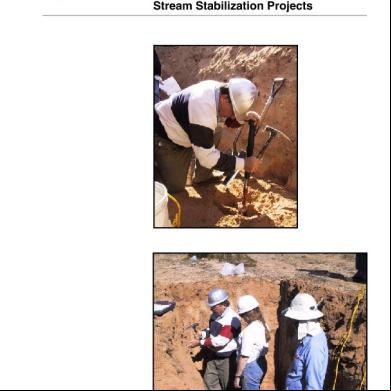
Alluvial Soil 465m8
November 2019 9
Alluvial Mine 6l5a2b
October 2020 0
Alluvial Anker 5v2c5a
August 2022 0
Alluvial Mining 175r4o
October 2020 0
Alluvial Mine Tugas Tamka 3r545m
April 2020 4