Abutment(1) 4y2d4m
This document was ed by and they confirmed that they have the permission to share it. If you are author or own the copyright of this book, please report to us by using this report form. Report r6l17
Overview 4q3b3c
& View Abutment(1) as PDF for free.
More details 26j3b
- Words: 4,998
- Pages: 31
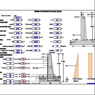
Design of Abutment for canal trough Name of work ;1
1.35
pkn
B.W.
DATA 2.00
m
F.S.D.
0.85
m
F.B.
0.3
m
m
Thickness
0.20
m
Width
2.00
m
0.85
2
Canal Trough Slab
Length Trough Side wall
8.00
3
Length
8.00
m
Thickness
0.3
m
Height
1.35
m
4
Road slab Length
8.00
m
Thickness
0.60
m
Width
0.00
m
5
Concrete Steel
20
conc. wt.
24000
N/m
3
Cover
50
mm 3.60
(HYSD)
sst 7
13.86 10.96
E/P M-
6
Canal trough height
190
N/m
2
J =
0.892
Soil wt
18000
R =
1.011
2.90
Soil Bearing capacity
8
Abutment Height (form footing)
9
wt of Water
160000 N/m2 13.86 10000
m
top width
0.85
F
N/m3 m
Length
N/m3
30 3.45
1.90
Heel
Degree
2.10 toe
7.60
m
0.85
10 REINFORCEMENT (I) STEM
E/P
Main
25
mm F @
50 mm c/c
Ditri.
10
mm F @
40 mm c/c
Tampr.
10
mm F @
80 mm c/c
20 20
mm F
70 mm c/c 140 mm c/c
13.86 10.96 E/P
Ep
Two way
(II) Toe Main Ditri.
mm F
3.60
1.90
(III) Heel Main Ditri.
20 20
2.90
mm F @
70 mm c/c mm F @ 140 mm c/c
2.10
7.60
Earth pressure
Load diagram
diagram [email protected]
Design of Abutment :pkn Name of work ;1 Load on Abutment :(I) Trough Slab Load = 1 x 2.00 x 8.00 x 0.20 x 24000 (ii) Trough Vertical wall load = 2 x 8.00 x 0.30 x 1.35 x 24000 (III) Water load from trough = 1 x 8.00 x 2.00 x 1.15 x 10000 (IV) Road Slab Load = 1 x 8.00 x 0.00 x 0.80 x 24000 50000 / R m (V) live load on S/R with (1.5x)empect load Assume Total load = Load on one Abutment will be 416320 = / 2 =
= 76800 N = 155520 N = 184000 N = 0 N = 0 N 416320 N 208160 N
2 Design assumption :Top Width of abutment = Bottom Width of Abutment
= Length of abutment =
Using
M 20
0.85 m 0.85 + 3.45 m
1.39 =
grade concrete
sst = 190 N/mm Wt. of soil = 18000 N/m3
2
J =
F = Wt. of water =
Height of Abutment = 13.86 Trough depth = 1.35 2.20 m Gross Height of Abutment = 15.21 Wt. of concrte = 24000 0.892 R = 1.011 Cover = 50 Bearing capacity of soil 30 = 160000 10000 N/m3
3 Diamension of base:The ratio of length of slabe (DE) to base width b is given by eq. q0 160000 1 = 1 = a = 2.2 y H 2.2 x #### x 15.21 …. Keep a = 0.73 The width of base is given by Eq. Ka 1-sin F 1 - 0.50 b = 0.95 H = = = Ka = (1- a)x(1+3 a) 1+sinF 1 + 0.5 0.333 x b = 0.95 x 15.21 = ( 1 - 0.73 )x( 1 + 2.19 ) The base width from the considration of sliding is given by Eq. 0.7HKa 0.7 x 15.21 x 0.33 b = = = 26.26 m (1-a) m ( 1 - 0.73 )x 0.5 This width is excessive. Normal practice is to provide b between 0.4 to 0.6 H . Taking maximum value of H = 0.5 = 7.60 b = 0.50 x 15.21 = m Hence Provided b = 7.60 m Width of toe slab = a x b = 0.27 x 7.60 = 2.05 m Provided toe slab = 2.10 Hence width of heel slab = 7.60 - 1.90 - 2.10 = 3.60 m Let the thickness of base be = H/12 = 15.21 / 12 = 1.27 or say = 1.30 m
m m m N/m3 mm N/m2
0.734 Eq (1)
0.333 8.98
m
m for design purpose
4 Thickness of stem:Heigth AB = 15.21 - 1.30 = 13.91 m consider 1 m length of retaining wall 0.333 x 18000 x( 13.86 )2 13.86 Maximum Bending k.y.h.H2 k.y.H3 + = 1.35 + = 3437063 moment at B = 2 2 6 3 3437063000 BM Effective depth required = = = 1844 1.011 Rxb x 1000 Keep, d = 1850 mm and total thick ness = 1850 + 50 say 1900 Reduce the total thickness to = 850 mm at top so that effective depth is = 800 5 Stability of wall:Full dimension wall is shown in fig 1a Let W 1 = weight of rectangular portion of stem w2 = weight of triangular portion of stem
n-m
mm mm mm
w3 = weight of base slab w4 = weight of soil on heel slab. w5 = Super imposed load over heel slab. The calculation are arrenged in Table Detail w1 1 x 0.85 x 13.91 x 24000 w2 1/2 x 1.05 x 13.91 x 24000 w3 1 x 7.60 x 1.30 x 24000 w4 1 x 3.60 x 13.91 x 18000 w5 1 x 1.35 x 3.60 x 18000 Sw (A) w6 Load from trough Sw (B) 7603519 Total resisting moment = kN-m
Total Earth pressure p =
Over turning moment
Ka x y x H2 = 2 579884 =
0.33 x x 3
18000
2 13.91
force(kN) lever arm 3.58 = 283764 175266 2.63 = 3.8 = 237120 5.8 = 901368 87480 5.8 = = 1597518 total MR 3.575 = 208160 1805678 =
Moment about toe
1014456 460073 901056 5227934 507384 7603519 744172 8347691
KN-m KN-m KN-m KN-m KN-m KN-m KN-m KN-m
..(1) x( 13.91 )2
=
579884
=
2688729
N
..(2) N-m
0.60 x 1597518 mSw = = 1.65 > 1.5 O.K. 579884 p 2688729 5658962 kN-m Pressure distribution net moment, SM = 8347691 = \ Distance x of the point of application of resultant, from toe is 5658962 b 7.60 SM = = 3.13 m = = 1.2667 x = 1805678 6 6 Sw b 7.60 Hence x = Eccenticity e = - 3.13 = 0.67 m < 1.2667 safe 2 2 1805678 Pressure p1 at 6e 6x 0.67 SW 1+ = = x 1+ = 362515 N/m2 toe 7.60 7.60 b b 1805678 Pressure p1 at 6e 6x 0.67 SW 1= = x 1= 112664 N/m2 Heel 7.60 7.60 b b Pressure p at the junction of stem with toe slab is 362515 - 112664 p = 362515 x 2.10 = 293477 N-m2 7.60 Pressure p at the junction of stem with Heel slab is 362515 - 112664 p = 362515 x 3.60 = 244165 N-m2 7.60 \F.S. against over turning (without trough load)
=
6 Design of toe slab:The weight of soil above the toe slab is neglicted . Thus two forces are acting on it (1) Up ward soil pressure (2) Down ward weight of slab Down ward weight of slab per unit area = 1.30 x 1 x #### = 31200 N/m2 Hence net pressureUnder D = 293477 31200 = 262277 N-m2 And at under E = 244165 31200 = 212965 N-m2 262277 212965 x Total force = S.F. at E = x 2.10 = 499004 N 2.00 212965 + 2.00 x 262277 2.10 CG of force at E = x = 1.09 m 212965 + 262277 3 499004.00 B.M. at E = 542076.00 x 1.09 = N-m \ 542076 x 1000 BM Effective depth required = = = 732 mm say 740 mm 1.011 Rxb x 1000 Keep effective depth d = 750 mm and total thickness = 800 mm
542076 1000 x 190 x 0.892 x 750 3.14 x dia2 using 20 mm bars A = 4 = 314 x 1000 \ 314 Area of steel provided per meter length = Ast =
BM x1000 = sst x j x D
= =
4265
mm2
3.14 x
20 4 74
/ 4265 = x 1000 = 70 shear force =
4486
x
20
=
314
mm say =
70
mm2
mm
mm2
499004 = 0.67 N/mm2 1000 x 750 100 x Ast 100 x 4486 Area of steel provide = = = 0.60 % b x d 1000 x 750 Permissible shear stress tc for 0.60 % steel provided, tc = 0.31 N/mm2 (see table 3.1) Here 0.67 > 0.31 unsafe, So increasing depth of slab, or reinforcemet Maximum permissible shear stress = 0.18 N/mm2 for 15 % steel 499004 shear force Minimum Depth Required = = = 2772 mm beam ht x tc 1000 x 0.18 100 x Ast 100 x 4486 Area of steel provide = = = 0.16 % b x d 1000 x 2772 Permissible shear stress for 0.16 % steel provided, tc = 0.18 N/mm2 (see table 3.1) 0.16 < 0.18 safe, provide effective depth = 2800 mm Total Depth 2800 + 100 = 2900 mm 70 Hence Provided 20 mm, F bar, @ mm c/c Provided Distribution 140 mm c/c 20 mm f @ Actual Shear stress tv
=
Beam Ht.x beam depth
7 Design of heel slab :Three force act on it 1. down ward weight of soil = 13.91 m 3 upward soil pressure 2 down ward weight of heel slab 1. Total weight of soil = 3.60 x 13.91 x 18000 = 901368 Acting at 1.80 m from B . 2. Total weight of heel slab = 3.60 x 1.30 x 24000 = 112320 Acting at 1.80 m from B . 3. Total upward soil pressure = 1/2 x( 244165 112664 )x 3.60 = 642292 N + 112664 244165 + 2 3.60 x m from B Acting at = x = 1.58 112664 244165 + 3 112320 - 642292 \ Total shear force at B = 901368 371396 N + = 112320 ) x 1.80 642292 \ B.M. At B =( 901368 + x 1.58 ) 810534 = N-m 810534 x 1000 BM Effective depth required = = = 895 mm 1.011 Rxb x 1000 Provide depth same as toe = 2800 mm and total thickness = 2800 + 50 = 2850 mm 810534 1000 BM x 1000 x Ast = = = 1709 mm2 190 x 0.892 x 2800 sst x j x D 3.14 x ( 20 )'2 P D2 Using 20 mm F bars, Area = = = 314 mm2 4 4 A x 1000 314 x 1000 Spacing = = = 183.73 mm say 180 mm Ast 1709
180 mm c/c 20 mm f @ 314 x 1000 Area of steel provide = = 1744 mm2 180 100As 100 x 1744 = = = 0.06 % Less than minimum steel bxd 1000 x 2800 Hence minimum steel provide = 0.15 % 0.15 = x 2800 x 1000 = 4200 mm2 100 Hence Provided
Using 20 mm F bars, Area =
\ Spacing =
1000 x 4200
P D2 = 4 314
=
3.14 x ( 4 75
20
)'2
mm say =
=
314
70
70 mm c/c 20 mm f @ 314 x 1000 Area of steel provide = = 4486 mm2 70 100As 100 x 4486 = = = 0.16 % bxd 1000 x 2800 shear force 371396 Shear stress t v = = Beam Ht.x beam wt. 1000 2800 x Permissible shear stress for 0.16 % steel provided t c = 0.18 N/mm2 O.K. Here 0.13 < 0.18 Provided Distribution 140 mm c/c 20 mm f @
mm2
mm c/c
Hence Provided
=
0.13
N/mm2
(See Table 3.1)
8 Reinforcement in the stem:2688729 Over turning Moment N-m = 2688729 x 1000 BM Effective depth required = = = 1631 mm say 1650 1.011 Rxb x 1000 Hence provide stem depth = effective depth = 1800 1900 mm - cover = 100 BM x 100 2688729 x 1000 Ast = = = 8814 mm2 sst x j x D 190 x 0.892 x 1800 3.14 x ( 25 )'2 P D2 Using 25 mm F bars, Area = = = 491 mm2 4 4 1000 x 491 Spacing = \ = 56 mm 8814 50 Hence Provided 25 mm, F bar, @ mm c/c Distribution and temprechure reinforcement:Average thickness of stem
=
1900
+ 2
850
=
1375
mm
0.12 x 1000 x 1375 = 1650 mm2 100 3.14 x ( 10 )'2 P D2 Using 10 mm F bars, Area = = = 79 mm2 4 4 1000 x 79 \ spacing = 48 mm say = 40 mm c/c = 1650 for tempreture reinforcement provide = 10 mm bars = 80 mm c/c both way in outer face \
Distribution reinforcement
=
mm mm
[email protected]
20
89
Bars /type C
34
41
15
44
19
46
25
27
#
44
16
56
16
46
20
Detail of Reinforcement per meter length length dia( length total lengh / space = number x row x @ wt /mt. = of bars of bar mm) of cc
64
total wt(kg)
Heel & toe main bottom top main Dist bottom Dist top
20 20 20 9
1000 1000 7600 7600
/ / / /
Stem main (vertical) 25 13860 / Stirrups (horz.) 8 10 / Total steel required
70 140
40
= = = =
15.00 70 55 140
x x x x
2 2 2 2
x x x x
1.55 2.5 1 1
= = = =
47 350 110 280
@ @ @ @
2.47 2.47 2.47 0.50
= = = =
116 864 272 140
= =
50 1
x x
4 2
x 6.43 = x 3.375 =
1286 7.00
@ 3.86 @ 0.40 Total
= = =
4961 3.00 6356
64
64
64
64
64
64
64
64
64
Table 1.15. PERMISSIBLE DIRECT TENSILE STRESS Grade of concrete
M-10
M-15
M-20
M-25
M-30
M-35
M-40
Tensile stress N/mm 2
1.2
2.0
2.8
3.2
3.6
4.0
4.4
Table 1.16.. Permissible stress in concrete (IS : 456-2000) Grade of concrete M M M M M M M M M
10 15 20 25 30 35 40 45 50
Permission stress in compression (N/mm 2) Permissible stress in bond (Average) for Bending acbc Direct (acc) plain bars in tention (N/mm2) (N/mm2) 3.0 5.0 7.0 8.5 10.0 11.5 13.0 14.5 16.0
Kg/m2 300 500 700 850 1000 1150 1300 1450 1600
(N/mm2) 2.5 4.0 5.0 6.0 8.0 9.0 10.0 11.0 12.0
Kg/m2 250 400 500 600 800 900 1000 1100 1200
in kg/m2 -60 80 90 100 110 120 130 140
(N/mm2) -0.6 0.8 0.9 1.0 1.1 1.2 1.3 1.4
Table 1.18. MODULAR RATIO Grade of concrete
Modular ratio m
M-10 31 (31.11)
M-15 19 (18.67)
M-20 13 (13.33)
M-25 11 (10.98)
M-30 9 (9.33)
M-35 8 (8.11)
Table 2.1. VALUES OF DESIGN CONSTANTS Grade of concrete Modular Ratio scbc N/mm2 m scbc kc (a) sst = jc 140 N/mm2 Rc (Fe 250) Pc (%)
M-15 18.67 5 93.33
M-20 13.33 7 93.33
M-25 10.98 8.5 93.33
M-30 9.33 10 93.33
M-35 8.11 11.5 93.33
M-40 7.18 13 93.33
0.4
0.4
0.4
0.4
0.4
0.4
0.867
0.867
0.867
0.867
0.867
0.867
0.867
1.214
1.474
1.734
1.994
2.254
0.714
1
1.214
1.429
1.643
1.857
kc (b) sst = j c 190 Rc N/mm2 Pc (%)
0.329
0.329
0.329
0.329
0.329
0.329
0.89 0.732
0.89
0.89
0.89
0.89
0.89
1.025
1.244
1.464
1.684
1.903
0.433
0.606
0.736
0.866
0.997
1.127
(c ) sst = 230 N/mm2 (Fe 415)
kc
0.289
0.289
0.289
0.289
0.289
0.289
jc
0.904
0.904
0.904
0.904
0.904
0.904
Rc
0.653
0.914
1.11
1.306
1.502
1.698
Pc (%)
0.314
0.44
0.534
0.628
0.722
0.816
(d) sst = 275 N/mm2 (Fe 500)
kc
0.253
0.253
0.253
0.253
0.253
0.253
M-40 7 (7.18)
(d) sst = 275 N/mm2 (Fe 500)
jc
0.916
0.916
0.916
0.914
0.916
0.916
Rc
0.579
0.811
0.985
1.159
1.332
1.506
Pc (%)
0.23
0.322
0.391
0.46
0.53
0.599
Shear stress tc 100As M-20 bd 0.15 0.18 0.16 0.18 0.17 0.18 0.18 0.19 0.19 0.19 0.2 0.19 0.21 0.2 0.22 0.2 0.23 0.2 0.24 0.21 0.25 0.21 0.26 0.21 0.27 0.22 0.28 0.22 0.29 0.22 0.3 0.23 0.31 0.23 0.32 0.24 0.33 0.24 0.34 0.24 0.35 0.25 0.36 0.25 0.37 0.25 0.38 0.26 0.39 0.26 0.4 0.26 0.41 0.27 0.42 0.27 0.43 0.27 0.44 0.28 0.45 0.28 0.46 0.28 0.47 0.29 0.48 0.29 0.49 0.29 0.5 0.30 0.51 0.30 0.52 0.30 0.53 0.30 0.54 0.30 0.55 0.31 0.56 0.31 0.57 0.31
Reiforcement % 100As M-20 bd 0.18 0.15 0.19 0.18 0.2 0.21 0.21 0.24 0.22 0.27 0.23 0.3 0.24 0.32 0.25 0.35 0.26 0.38 0.27 0.41 0.28 0.44 0.29 0.47 0.30 0.5 0.31 0.55 0.32 0.6 0.33 0.65 0.34 0.7 0.35 0.75 0.36 0.82 0.37 0.88 0.38 0.94 0.39 1.00 0.4 1.08 0.41 1.16 0.42 1.25 0.43 1.33 0.44 1.41 0.45 1.50 0.46 1.63 0.46 1.64 0.47 1.75 0.48 1.88 0.49 2.00 0.50 2.13 0.51 2.25
0.58 0.59 0.6 0.61 0.62 0.63 0.64 0.65 0.66 0.67 0.68 0.69 0.7 0.71 0.72 0.73 0.74 0.75 0.76 0.77 0.78 0.79 0.8 0.81 0.82 0.83 0.84 0.85 0.86 0.87 0.88 0.89 0.9 0.91 0.92 0.93 0.94 0.95 0.96 0.97 0.98 0.99 1.00 1.01 1.02 1.03 1.04 1.05 1.06 1.07 1.08 1.09
0.31 0.31 0.32 0.32 0.32 0.32 0.32 0.33 0.33 0.33 0.33 0.33 0.34 0.34 0.34 0.34 0.34 0.35 0.35 0.35 0.35 0.35 0.35 0.35 0.36 0.36 0.36 0.36 0.36 0.36 0.37 0.37 0.37 0.37 0.37 0.37 0.38 0.38 0.38 0.38 0.38 0.38 0.39 0.39 0.39 0.39 0.39 0.39 0.39 0.39 0.4 0.4
1.10 1.11 1.12 1.13 1.14 1.15 1.16 1.17 1.18 1.19 1.20 1.21 1.22 1.23 1.24 1.25 1.26 1.27 1.28 1.29 1.30 1.31 1.32 1.33 1.34 1.35 1.36 1.37 1.38 1.39 1.40 1.41 1.42 1.43 1.44 1.45 1.46 1.47 1.48 1.49 1.50 1.51 1.52 1.53 1.54 1.55 1.56 1.57 1.58 1.59 1.60 1.61
0.4 0.4 0.4 0.4 0.4 0.4 0.41 0.41 0.41 0.41 0.41 0.41 0.41 0.41 0.41 0.42 0.42 0.42 0.42 0.42 0.42 0.42 0.42 0.43 0.43 0.43 0.43 0.43 0.43 0.43 0.43 0.44 0.44 0.44 0.44 0.44 0.44 0.44 0.44 0.44 0.45 0.45 0.45 0.45 0.45 0.45 0.45 0.45 0.45 0.45 0.45 0.45
1.62 1.63 1.64 1.65 1.66 1.67 1.68 1.69 1.70 1.71 1.72 1.73 1.74 1.75 1.76 1.77 1.78 1.79 1.80 1.81 1.82 1.83 1.84 1.85 1.86 1.87 1.88 1.89 1.90 1.91 1.92 1.93 1.94 1.95 1.96 1.97 1.98 1.99 2.00 2.01 2.02 2.03 2.04 2.05 2.06 2.07 2.08 2.09 2.10 2.11 2.12 2.13
0.45 0.46 0.46 0.46 0.46 0.46 0.46 0.46 0.46 0.46 0.46 0.46 0.46 0.47 0.47 0.47 0.47 0.47 0.47 0.47 0.47 0.47 0.47 0.47 0.47 0.47 0.48 0.48 0.48 0.48 0.48 0.48 0.48 0.48 0.48 0.48 0.48 0.48 0.49 0.49 0.49 0.49 0.49 0.49 0.49 0.49 0.49 0.49 0.49 0.49 0.49 0.50
2.14 2.15 2.16 2.17 2.18 2.19 2.20 2.21 2.22 2.23 2.24 2.25 2.26 2.27 2.28 2.29 2.30 2.31 2.32 2.33 2.34 2.35 2.36 2.37 2.38 2.39 2.40 2.41 2.42 2.43 2.44 2.45 2.46 2.47 2.48 2.49 2.50 2.51 2.52 2.53 2.54 2.55 2.56 2.57 2.58 2.59 2.60 2.61 2.62 2.63 2.64 2.65
0.50 0.50 0.50 0.50 0.50 0.50 0.50 0.50 0.50 0.50 0.50 0.51 0.51 0.51 0.51 0.51 0.51 0.51 0.51 0.51 0.51 0.51 0.51 0.51 0.51 0.51 0.51 0.51 0.51 0.51 0.51 0.51 0.51 0.51 0.51 0.51 0.51 0.51 0.51 0.51 0.51 0.51 0.51 0.51 0.51 0.51 0.51 0.51 0.51 0.51 0.51 0.51
2.66 2.67 2.68 2.69 2.70 2.71 2.72 2.73 2.74 2.75 2.76 2.77 2.78 2.79 2.80 2.81 2.82 2.83 2.84 2.85 2.86 2.87 2.88 2.89 2.90 2.91 2.92 2.93 2.94 2.95 2.96 2.97 2.98 2.99 3.00 3.01 3.02 3.03 3.04 3.05 3.06 3.07 3.08 3.09 3.10 3.11 3.12 3.13 3.14 3.15
0.51 0.51 0.51 0.51 0.51 0.51 0.51 0.51 0.51 0.51 0.51 0.51 0.51 0.51 0.51 0.51 0.51 0.51 0.51 0.51 0.51 0.51 0.51 0.51 0.51 0.51 0.51 0.51 0.51 0.51 0.51 0.51 0.51 0.51 0.51 0.51 0.51 0.51 0.51 0.51 0.51 0.51 0.51 0.51 0.51 0.51 0.51 0.51 0.51 0.51
64
110
64
64
64
64
64
64
64
Table 3.1. Permissible shear stress Table tc in concrete (IS : 456-2000) 100As bd < 0.15 0.25 0.50 0.75 1.00 1.25 1.50 1.75 2.00 2.25 2.50 2.75
Permissible shear stress in concrete M-15 M-20 M-25 M-30 0.18 0.18 0.19 0.2 0.22 0.22 0.23 0.23 0.29 0.30 0.31 0.31 0.34 0.35 0.36 0.37 0.37 0.39 0.40 0.41 0.40 0.42 0.44 0.45 0.42 0.45 0.46 0.48 0.44 0.47 0.49 0.50 0.44 0.49 0.51 0.53 0.44 0.51 0.53 0.55 0.44 0.51 0.55 0.57 0.44 0.51 0.56 0.58 0.44 0.51 0.57 0.6
% % % % % % % % % % % %
3.00 and above %
tc N/mm2 M-35 M-40 0.2 0.2 0.23 0.23 0.31 0.32 0.37 0.38 0.42 0.42 0.45 0.46 0.49 0.49 0.52 0.52 0.54 0.55 0.56 0.57 0.58 0.60 0.60 0.62 0.62 0.63
Table 3.2. Facor k Over all depth of slab
300 oe more
k
1.00
275 1.05
250 1.10
225 1.15
200 1.20
175 1.25
Table 3.3. Maximum shear stress tc.max in concrete (IS : 456-2000) Grade of concrete
M-15 1.6
tc.max
M-20 1.8
M-25 1.9
M-30 2.2
M-35 2.3
M-40 2.5
Table 3.4. Permissible Bond stress Table tbd in concrete (IS : 456-2000) Grade of concrete M tbd (N / mm2)
10 --
15 0.6
20 0.8
25 0.9
30 1
35 1.1
40 1.2
Table 3.5. Development Length in tension Plain M.S. Bars
Grade of concrete tbd (N / mm2)
H.Y.S.D. Bars
kd = Ld F
tbd (N / mm2)
kd = Ld F
M 15 M 20
0.6
58
0.96
60
0.8
44
1.28
45
M 25 M 30
0.9
39
1.44
40
1
35
1.6
36
M 35 M 40
1.1
32
1.76
33
1.2
29
1.92
30
M 45 M 50
1.3
27
2.08
28
1.4
25
2.24
26
64
64
150 or less 1.30
(IS : 456-2000) 45 1.3
.D. Bars kd = Ld F 60 45 40 36 33 30 28 26
50 1.4
64 nos main bars
89 nos main bars
o o
o
o o
o
210
o
o
o
o
o
o
o
o
o
o
o o
Distribution bars 10mm F 250 c/c 1688
150
o
150
150
o
12mm F 85 c/c
150
12mm F 120 c/c 8mm F 160 c/c 1256
450
450
7500 6600 Wearing coat 75mm thick
Distribution bars
o
o o
o
o o
o
240
o o
o o
o
o o
o
Cross section of culvert
Distribution bars 10mm F 175 c/c
o o
o
o o
o
o o
o
o
300
o o
o
o o
o
o o
o
72 nos main bars 16mm F 105 c/c o
o
220
3000 2810
Distribution bars 12mm F 200 c/c 3330
o o
300 506
300
150
o
2000 1960
2.00 m span
150
o
300 416
1.50 m span
150
150
2508
300
160
61 nos main bars 16mm F 125 c/c
1500 1575
130
300 375
300
o
o o
3.00 m span
o o
o
o o
o
o o
o
370
o o
o o
o
o o
o
o o
o
4000 3650
290
300 590
o
o o
o
300
4.00 m span 55 nos main bars 20mm F 140 c/c
Distribution bars 12mm F 175 c/c
o o
o o
o
o o
o
o
430
1 4 5 6
o o
o
o o
o
o o
o
o o
o
o
o
o
o
o
400
4840 o
o
400 890
o
400
NOTES:-
o
5000 4570
320
400 790
o
150
o o
Distribution bars 12mm F 150 c/c
150
o
150
150
4040
o
66 nos main bars 20mm F 115 c/c
o o
o
o o
o
o o
o
o o
o
480 6000 5360
o o
o o
o
o o
o
o o
o
o o
o
o o
o
400
5.00 m span 6.00 m span Concrete:- M-25 2 Steel:- HSDY as per IS-1786 3 Cover:- 20mmat bottom & 40mm at side In 1.5M, 2.0M &3.0M span only one Bar is to be crankedin each side in four bars in all other span crank alternative bars. All bars cranked one end onlythese are placed with crank on left side and right side alternatively Surface steel at top longitudinal -10mm @300mm c/c length a shown in sketh & transverse -10mm @300c/c all through out in logitudinal provided steel in the Zone where main steel is not available plus 150mm on either side
84 nos main bars 20mm F 90 c/c
Distribution bars 12mm F 125 c/c
o
o o
o
o o
o
o o
o
o o
o
o o
o
o
600
o o
o
o o
o
o o
o
o o
o
o o
o
8000 7280
520
400 1120
150
150 o
6680
o o
o
400
8.00 m span 64 nos main bars 25mm F 120 c/c
Distribution bars 12mm F 110 c/c
o
o
o
o
o
o
o
o
o
o
o
o
o
o
o
o
o
o
o
o
o
o
o
o
o
o
670
400 1260
150
150
8400 750 10000 8990
10.00 m span
o
o
o
o
o
o
o
o
o
o
o
o
o
o
o
o
o
o
o
o
o
o
o
o
o
o
400
Area & weight of tor Bar F 6 8 10 12 14 16 18 20 22 25 28 32 36 40 50
Area 0.283 0.503 0.785 1.131 1.539 2.011 2.545 3.142 3.801 4.909 6.157 8.04 10.17 12.56 19.635 0.888
wt/m 0.222 0.395 0.617 0.888 1.208 1.578 2 2.466 2.98 3.854 4.83 6.31 7.98 9.85 15.40
density 0.784 0.785 0.786 0.785 0.785 0.785 0.786 0.785 0.784 0.785 0.784 0.784 0.784 0.784 0.784
Cear Road Way 225
225
4500
Anker Bars for parapet post
o
o
o
o o
o
o
o
o
o
o
oo
o
o
oo
o
oo
o
oo
o
o
oo
o
o
oo
o
o
oo
o
o
oo
o
o
oo
o
o
oo
o
oo
o
o
Clear span of slab
Bearing length at end
Over all length of Slab
Over all Depth of Slab
Dia (mm)
Spacing (mm)
No of Bars
X (mm)
Y (mm)
Dia (mm)
Spacing (mm)
No of Bars
Steel in Longitudinal Di
3
0.37
3.74
275
16
150
50
0.553
0.296
2.10
4.036
201.8
18
150
57
3.622
4
0.37
4.74
345
16
150
50
0.833
0.395
2.80
5.144
257.2
20
150
57
4.690
5
0.37
5.74
395
20
150
50
0.735
0.460
3.50
6.258
312.9
20
150
57
5.629
6
0.37
6.74
445
16
150
50
0.833
0.557
4.20
7.298
364.9
25
150
57
6.615
8
0.37
8.74
555
22
150
50
1.020
0.683
5.60
9.414
470.7
25
150
57
8.615
L (mm)
Z (mm)
Total length in M
Type 'B' 2*(x+y)+zh ook(m)
Type 'A'
Steel in Transverse Direction Type 'F'
25
8.15
8.442
211.1
10
300
13
8.0
8.18
106.3
150
32
8.15
8.442
270.1
10
300
17
8.0
8.18
139.1
5
0.37
5.74
395
16
150
38
8.15
8.442
320.8
10
300
20
8.0
8.18
163.6
6
0.37
6.74
445
16
150
45
8.15
8.442
379.9
10
300
23
8.0
8.18
188.1
8
0.37
8.74
555
16
150
58
8.15
8.442
489.6
10
300
30
8.0
8.18
245.4
No of Bars
No of Bars
Dia (mm)
Total length in M
150
16
H+ hook (M)
Total length in M
16
345
L (mm)
R+ hook (M)
275
4.74
Spacing (mm)
Over all Depth of Slab
3.74
0.37
Dia (mm)
Over all length of Slab
0.37
4
R' (mm)
Bearing length at end
3
Spacing (mm)
Clear span of slab
Type 'E'
MAXIMUM REACTION IN TONNES Span 3 4
D.L. 14.2 21.6
At Abutment D.L.+L.L. D.L.+L.L.+I 52.05 70.26 61.36 78.8
At Peir D.L. 28.3 43.2
D.L.+L.L. 75.75 94.8
D.L.+L.L.+I 87.61 107.7
5 6 8
29.2 38.1 57.6
70.92 82.13 107.4
87.55 98.21 119.8
58.3 76.2 115.2
114.1 132.9 174.6
127.3 144.9 189.7
225
o
o
o
oo
o
oo
o
o
oo
o
o
oo
225
o
o
oo
o
oo
o
oo
o
Steel in Longitudinal Direction
Spacing (mm)
No of Bars
m (mm)
m' (mm)
Dia (mm)
No of Bars
3.98
227.0
10
300
24
3.63
0.215
4.34
104.2
10
10
3.63
3.81
38.1
5.09
290.1
10
300
24
4.63
0.265
5.38
129.1
10
10
4.63
4.81
48.1
6.03
343.7
10
300
24
5.63
0.335
6.48
155.5
10
10
5.63
5.81
58.1
7.12
405.6
10
300
24
6.63
0.385
7.58
181.9
10
10
6.63
6.81
68.1
9.12
519.6
10
300
24
8.63
0.495
9.80
235.2
10
10
8.63
8.81
88.1
D.L.+L.L.+I 87.61 107.7
10
300
26
255
344
2.171
56.4
10
300
34
325
352
2.32
78.9
10
300
40
375
358
2.436
97.4
10
300
46
425
368
2.532
116.5
10
300
60
530
375
2.754
165.2
1.454 1.878 2.587 3.217 4.817
Total Quantity of Cocreteper span in cubic meters
Total length in M
Y' (mm)
m+ 'm'+ hook M
X (mm)
No of Bars
Spacing (mm)
Dia (mm)
Type 'G'
Total quantity of M.S. Reinforcement per span in Tons
in Transverse Direction
9.46 14.69 20.1 26.4 44.2
J (mm)
Dia (mm)
R+ hook (M) Total length in M
Type 'D' m+ 'm'+ hook M Total length in M
Type 'C' m' L+ hook M Total length in M
Type 'B'
127.3 144.9 189.7
MAXIMUM REACTION IN TONNES Span 3.m 4m 5m 6m 8m
D.L. 14.15 21.6 29.15 38.1 57.6
At Abutment D.L.+L.L. D.L.+L.L.+I.L. 52.05 79.26 61.36 78.8 70.92 87.55 82.13 98.21 107.40 119.8
D.L. 28.3 43.2 58.3 76.2 115.2
MAXIMUM REACTION IN TONNES Span
At Abutment Live load Impect load. 37.9 27.21
3.m
Dead load 14.15
4m 5m 6m
21.6 29.15 38.1
39.76 41.77 44.03
17.44 16.63 16.08
78.8 87.55 98.21
8m
57.6
49.8
12.4
119.8
Span 3.m 4m 5m 6m 8m
MAXIMUM REACTION IN TONNES Dead load Live load Impect Load 28.3 47.45 11.86 43.2 51.6 12.9 58.3 55.8 13.2 76.2 56.7 12 115.2 59.4 15.1
Total load 79.26
Total load 87.61 107.7 127.3 144.9 189.7
At Pier D.L.+L.L. 75.75 94.8 114.1 132.9 174.6
D.L.+L.L.+I.L. 87.61 107.7 127.3 144.9 189.7
1.35
pkn
B.W.
DATA 2.00
m
F.S.D.
0.85
m
F.B.
0.3
m
m
Thickness
0.20
m
Width
2.00
m
0.85
2
Canal Trough Slab
Length Trough Side wall
8.00
3
Length
8.00
m
Thickness
0.3
m
Height
1.35
m
4
Road slab Length
8.00
m
Thickness
0.60
m
Width
0.00
m
5
Concrete Steel
20
conc. wt.
24000
N/m
3
Cover
50
mm 3.60
(HYSD)
sst 7
13.86 10.96
E/P M-
6
Canal trough height
190
N/m
2
J =
0.892
Soil wt
18000
R =
1.011
2.90
Soil Bearing capacity
8
Abutment Height (form footing)
9
wt of Water
160000 N/m2 13.86 10000
m
top width
0.85
F
N/m3 m
Length
N/m3
30 3.45
1.90
Heel
Degree
2.10 toe
7.60
m
0.85
10 REINFORCEMENT (I) STEM
E/P
Main
25
mm F @
50 mm c/c
Ditri.
10
mm F @
40 mm c/c
Tampr.
10
mm F @
80 mm c/c
20 20
mm F
70 mm c/c 140 mm c/c
13.86 10.96 E/P
Ep
Two way
(II) Toe Main Ditri.
mm F
3.60
1.90
(III) Heel Main Ditri.
20 20
2.90
mm F @
70 mm c/c mm F @ 140 mm c/c
2.10
7.60
Earth pressure
Load diagram
diagram [email protected]
Design of Abutment :pkn Name of work ;1 Load on Abutment :(I) Trough Slab Load = 1 x 2.00 x 8.00 x 0.20 x 24000 (ii) Trough Vertical wall load = 2 x 8.00 x 0.30 x 1.35 x 24000 (III) Water load from trough = 1 x 8.00 x 2.00 x 1.15 x 10000 (IV) Road Slab Load = 1 x 8.00 x 0.00 x 0.80 x 24000 50000 / R m (V) live load on S/R with (1.5x)empect load Assume Total load = Load on one Abutment will be 416320 = / 2 =
= 76800 N = 155520 N = 184000 N = 0 N = 0 N 416320 N 208160 N
2 Design assumption :Top Width of abutment = Bottom Width of Abutment
= Length of abutment =
Using
M 20
0.85 m 0.85 + 3.45 m
1.39 =
grade concrete
sst = 190 N/mm Wt. of soil = 18000 N/m3
2
J =
F = Wt. of water =
Height of Abutment = 13.86 Trough depth = 1.35 2.20 m Gross Height of Abutment = 15.21 Wt. of concrte = 24000 0.892 R = 1.011 Cover = 50 Bearing capacity of soil 30 = 160000 10000 N/m3
3 Diamension of base:The ratio of length of slabe (DE) to base width b is given by eq. q0 160000 1 = 1 = a = 2.2 y H 2.2 x #### x 15.21 …. Keep a = 0.73 The width of base is given by Eq. Ka 1-sin F 1 - 0.50 b = 0.95 H = = = Ka = (1- a)x(1+3 a) 1+sinF 1 + 0.5 0.333 x b = 0.95 x 15.21 = ( 1 - 0.73 )x( 1 + 2.19 ) The base width from the considration of sliding is given by Eq. 0.7HKa 0.7 x 15.21 x 0.33 b = = = 26.26 m (1-a) m ( 1 - 0.73 )x 0.5 This width is excessive. Normal practice is to provide b between 0.4 to 0.6 H . Taking maximum value of H = 0.5 = 7.60 b = 0.50 x 15.21 = m Hence Provided b = 7.60 m Width of toe slab = a x b = 0.27 x 7.60 = 2.05 m Provided toe slab = 2.10 Hence width of heel slab = 7.60 - 1.90 - 2.10 = 3.60 m Let the thickness of base be = H/12 = 15.21 / 12 = 1.27 or say = 1.30 m
m m m N/m3 mm N/m2
0.734 Eq (1)
0.333 8.98
m
m for design purpose
4 Thickness of stem:Heigth AB = 15.21 - 1.30 = 13.91 m consider 1 m length of retaining wall 0.333 x 18000 x( 13.86 )2 13.86 Maximum Bending k.y.h.H2 k.y.H3 + = 1.35 + = 3437063 moment at B = 2 2 6 3 3437063000 BM Effective depth required = = = 1844 1.011 Rxb x 1000 Keep, d = 1850 mm and total thick ness = 1850 + 50 say 1900 Reduce the total thickness to = 850 mm at top so that effective depth is = 800 5 Stability of wall:Full dimension wall is shown in fig 1a Let W 1 = weight of rectangular portion of stem w2 = weight of triangular portion of stem
n-m
mm mm mm
w3 = weight of base slab w4 = weight of soil on heel slab. w5 = Super imposed load over heel slab. The calculation are arrenged in Table Detail w1 1 x 0.85 x 13.91 x 24000 w2 1/2 x 1.05 x 13.91 x 24000 w3 1 x 7.60 x 1.30 x 24000 w4 1 x 3.60 x 13.91 x 18000 w5 1 x 1.35 x 3.60 x 18000 Sw (A) w6 Load from trough Sw (B) 7603519 Total resisting moment = kN-m
Total Earth pressure p =
Over turning moment
Ka x y x H2 = 2 579884 =
0.33 x x 3
18000
2 13.91
force(kN) lever arm 3.58 = 283764 175266 2.63 = 3.8 = 237120 5.8 = 901368 87480 5.8 = = 1597518 total MR 3.575 = 208160 1805678 =
Moment about toe
1014456 460073 901056 5227934 507384 7603519 744172 8347691
KN-m KN-m KN-m KN-m KN-m KN-m KN-m KN-m
..(1) x( 13.91 )2
=
579884
=
2688729
N
..(2) N-m
0.60 x 1597518 mSw = = 1.65 > 1.5 O.K. 579884 p 2688729 5658962 kN-m Pressure distribution net moment, SM = 8347691 = \ Distance x of the point of application of resultant, from toe is 5658962 b 7.60 SM = = 3.13 m = = 1.2667 x = 1805678 6 6 Sw b 7.60 Hence x = Eccenticity e = - 3.13 = 0.67 m < 1.2667 safe 2 2 1805678 Pressure p1 at 6e 6x 0.67 SW 1+ = = x 1+ = 362515 N/m2 toe 7.60 7.60 b b 1805678 Pressure p1 at 6e 6x 0.67 SW 1= = x 1= 112664 N/m2 Heel 7.60 7.60 b b Pressure p at the junction of stem with toe slab is 362515 - 112664 p = 362515 x 2.10 = 293477 N-m2 7.60 Pressure p at the junction of stem with Heel slab is 362515 - 112664 p = 362515 x 3.60 = 244165 N-m2 7.60 \F.S. against over turning (without trough load)
=
6 Design of toe slab:The weight of soil above the toe slab is neglicted . Thus two forces are acting on it (1) Up ward soil pressure (2) Down ward weight of slab Down ward weight of slab per unit area = 1.30 x 1 x #### = 31200 N/m2 Hence net pressureUnder D = 293477 31200 = 262277 N-m2 And at under E = 244165 31200 = 212965 N-m2 262277 212965 x Total force = S.F. at E = x 2.10 = 499004 N 2.00 212965 + 2.00 x 262277 2.10 CG of force at E = x = 1.09 m 212965 + 262277 3 499004.00 B.M. at E = 542076.00 x 1.09 = N-m \ 542076 x 1000 BM Effective depth required = = = 732 mm say 740 mm 1.011 Rxb x 1000 Keep effective depth d = 750 mm and total thickness = 800 mm
542076 1000 x 190 x 0.892 x 750 3.14 x dia2 using 20 mm bars A = 4 = 314 x 1000 \ 314 Area of steel provided per meter length = Ast =
BM x1000 = sst x j x D
= =
4265
mm2
3.14 x
20 4 74
/ 4265 = x 1000 = 70 shear force =
4486
x
20
=
314
mm say =
70
mm2
mm
mm2
499004 = 0.67 N/mm2 1000 x 750 100 x Ast 100 x 4486 Area of steel provide = = = 0.60 % b x d 1000 x 750 Permissible shear stress tc for 0.60 % steel provided, tc = 0.31 N/mm2 (see table 3.1) Here 0.67 > 0.31 unsafe, So increasing depth of slab, or reinforcemet Maximum permissible shear stress = 0.18 N/mm2 for 15 % steel 499004 shear force Minimum Depth Required = = = 2772 mm beam ht x tc 1000 x 0.18 100 x Ast 100 x 4486 Area of steel provide = = = 0.16 % b x d 1000 x 2772 Permissible shear stress for 0.16 % steel provided, tc = 0.18 N/mm2 (see table 3.1) 0.16 < 0.18 safe, provide effective depth = 2800 mm Total Depth 2800 + 100 = 2900 mm 70 Hence Provided 20 mm, F bar, @ mm c/c Provided Distribution 140 mm c/c 20 mm f @ Actual Shear stress tv
=
Beam Ht.x beam depth
7 Design of heel slab :Three force act on it 1. down ward weight of soil = 13.91 m 3 upward soil pressure 2 down ward weight of heel slab 1. Total weight of soil = 3.60 x 13.91 x 18000 = 901368 Acting at 1.80 m from B . 2. Total weight of heel slab = 3.60 x 1.30 x 24000 = 112320 Acting at 1.80 m from B . 3. Total upward soil pressure = 1/2 x( 244165 112664 )x 3.60 = 642292 N + 112664 244165 + 2 3.60 x m from B Acting at = x = 1.58 112664 244165 + 3 112320 - 642292 \ Total shear force at B = 901368 371396 N + = 112320 ) x 1.80 642292 \ B.M. At B =( 901368 + x 1.58 ) 810534 = N-m 810534 x 1000 BM Effective depth required = = = 895 mm 1.011 Rxb x 1000 Provide depth same as toe = 2800 mm and total thickness = 2800 + 50 = 2850 mm 810534 1000 BM x 1000 x Ast = = = 1709 mm2 190 x 0.892 x 2800 sst x j x D 3.14 x ( 20 )'2 P D2 Using 20 mm F bars, Area = = = 314 mm2 4 4 A x 1000 314 x 1000 Spacing = = = 183.73 mm say 180 mm Ast 1709
180 mm c/c 20 mm f @ 314 x 1000 Area of steel provide = = 1744 mm2 180 100As 100 x 1744 = = = 0.06 % Less than minimum steel bxd 1000 x 2800 Hence minimum steel provide = 0.15 % 0.15 = x 2800 x 1000 = 4200 mm2 100 Hence Provided
Using 20 mm F bars, Area =
\ Spacing =
1000 x 4200
P D2 = 4 314
=
3.14 x ( 4 75
20
)'2
mm say =
=
314
70
70 mm c/c 20 mm f @ 314 x 1000 Area of steel provide = = 4486 mm2 70 100As 100 x 4486 = = = 0.16 % bxd 1000 x 2800 shear force 371396 Shear stress t v = = Beam Ht.x beam wt. 1000 2800 x Permissible shear stress for 0.16 % steel provided t c = 0.18 N/mm2 O.K. Here 0.13 < 0.18 Provided Distribution 140 mm c/c 20 mm f @
mm2
mm c/c
Hence Provided
=
0.13
N/mm2
(See Table 3.1)
8 Reinforcement in the stem:2688729 Over turning Moment N-m = 2688729 x 1000 BM Effective depth required = = = 1631 mm say 1650 1.011 Rxb x 1000 Hence provide stem depth = effective depth = 1800 1900 mm - cover = 100 BM x 100 2688729 x 1000 Ast = = = 8814 mm2 sst x j x D 190 x 0.892 x 1800 3.14 x ( 25 )'2 P D2 Using 25 mm F bars, Area = = = 491 mm2 4 4 1000 x 491 Spacing = \ = 56 mm 8814 50 Hence Provided 25 mm, F bar, @ mm c/c Distribution and temprechure reinforcement:Average thickness of stem
=
1900
+ 2
850
=
1375
mm
0.12 x 1000 x 1375 = 1650 mm2 100 3.14 x ( 10 )'2 P D2 Using 10 mm F bars, Area = = = 79 mm2 4 4 1000 x 79 \ spacing = 48 mm say = 40 mm c/c = 1650 for tempreture reinforcement provide = 10 mm bars = 80 mm c/c both way in outer face \
Distribution reinforcement
=
mm mm
[email protected]
20
89
Bars /type C
34
41
15
44
19
46
25
27
#
44
16
56
16
46
20
Detail of Reinforcement per meter length length dia( length total lengh / space = number x row x @ wt /mt. = of bars of bar mm) of cc
64
total wt(kg)
Heel & toe main bottom top main Dist bottom Dist top
20 20 20 9
1000 1000 7600 7600
/ / / /
Stem main (vertical) 25 13860 / Stirrups (horz.) 8 10 / Total steel required
70 140
40
= = = =
15.00 70 55 140
x x x x
2 2 2 2
x x x x
1.55 2.5 1 1
= = = =
47 350 110 280
@ @ @ @
2.47 2.47 2.47 0.50
= = = =
116 864 272 140
= =
50 1
x x
4 2
x 6.43 = x 3.375 =
1286 7.00
@ 3.86 @ 0.40 Total
= = =
4961 3.00 6356
64
64
64
64
64
64
64
64
64
Table 1.15. PERMISSIBLE DIRECT TENSILE STRESS Grade of concrete
M-10
M-15
M-20
M-25
M-30
M-35
M-40
Tensile stress N/mm 2
1.2
2.0
2.8
3.2
3.6
4.0
4.4
Table 1.16.. Permissible stress in concrete (IS : 456-2000) Grade of concrete M M M M M M M M M
10 15 20 25 30 35 40 45 50
Permission stress in compression (N/mm 2) Permissible stress in bond (Average) for Bending acbc Direct (acc) plain bars in tention (N/mm2) (N/mm2) 3.0 5.0 7.0 8.5 10.0 11.5 13.0 14.5 16.0
Kg/m2 300 500 700 850 1000 1150 1300 1450 1600
(N/mm2) 2.5 4.0 5.0 6.0 8.0 9.0 10.0 11.0 12.0
Kg/m2 250 400 500 600 800 900 1000 1100 1200
in kg/m2 -60 80 90 100 110 120 130 140
(N/mm2) -0.6 0.8 0.9 1.0 1.1 1.2 1.3 1.4
Table 1.18. MODULAR RATIO Grade of concrete
Modular ratio m
M-10 31 (31.11)
M-15 19 (18.67)
M-20 13 (13.33)
M-25 11 (10.98)
M-30 9 (9.33)
M-35 8 (8.11)
Table 2.1. VALUES OF DESIGN CONSTANTS Grade of concrete Modular Ratio scbc N/mm2 m scbc kc (a) sst = jc 140 N/mm2 Rc (Fe 250) Pc (%)
M-15 18.67 5 93.33
M-20 13.33 7 93.33
M-25 10.98 8.5 93.33
M-30 9.33 10 93.33
M-35 8.11 11.5 93.33
M-40 7.18 13 93.33
0.4
0.4
0.4
0.4
0.4
0.4
0.867
0.867
0.867
0.867
0.867
0.867
0.867
1.214
1.474
1.734
1.994
2.254
0.714
1
1.214
1.429
1.643
1.857
kc (b) sst = j c 190 Rc N/mm2 Pc (%)
0.329
0.329
0.329
0.329
0.329
0.329
0.89 0.732
0.89
0.89
0.89
0.89
0.89
1.025
1.244
1.464
1.684
1.903
0.433
0.606
0.736
0.866
0.997
1.127
(c ) sst = 230 N/mm2 (Fe 415)
kc
0.289
0.289
0.289
0.289
0.289
0.289
jc
0.904
0.904
0.904
0.904
0.904
0.904
Rc
0.653
0.914
1.11
1.306
1.502
1.698
Pc (%)
0.314
0.44
0.534
0.628
0.722
0.816
(d) sst = 275 N/mm2 (Fe 500)
kc
0.253
0.253
0.253
0.253
0.253
0.253
M-40 7 (7.18)
(d) sst = 275 N/mm2 (Fe 500)
jc
0.916
0.916
0.916
0.914
0.916
0.916
Rc
0.579
0.811
0.985
1.159
1.332
1.506
Pc (%)
0.23
0.322
0.391
0.46
0.53
0.599
Shear stress tc 100As M-20 bd 0.15 0.18 0.16 0.18 0.17 0.18 0.18 0.19 0.19 0.19 0.2 0.19 0.21 0.2 0.22 0.2 0.23 0.2 0.24 0.21 0.25 0.21 0.26 0.21 0.27 0.22 0.28 0.22 0.29 0.22 0.3 0.23 0.31 0.23 0.32 0.24 0.33 0.24 0.34 0.24 0.35 0.25 0.36 0.25 0.37 0.25 0.38 0.26 0.39 0.26 0.4 0.26 0.41 0.27 0.42 0.27 0.43 0.27 0.44 0.28 0.45 0.28 0.46 0.28 0.47 0.29 0.48 0.29 0.49 0.29 0.5 0.30 0.51 0.30 0.52 0.30 0.53 0.30 0.54 0.30 0.55 0.31 0.56 0.31 0.57 0.31
Reiforcement % 100As M-20 bd 0.18 0.15 0.19 0.18 0.2 0.21 0.21 0.24 0.22 0.27 0.23 0.3 0.24 0.32 0.25 0.35 0.26 0.38 0.27 0.41 0.28 0.44 0.29 0.47 0.30 0.5 0.31 0.55 0.32 0.6 0.33 0.65 0.34 0.7 0.35 0.75 0.36 0.82 0.37 0.88 0.38 0.94 0.39 1.00 0.4 1.08 0.41 1.16 0.42 1.25 0.43 1.33 0.44 1.41 0.45 1.50 0.46 1.63 0.46 1.64 0.47 1.75 0.48 1.88 0.49 2.00 0.50 2.13 0.51 2.25
0.58 0.59 0.6 0.61 0.62 0.63 0.64 0.65 0.66 0.67 0.68 0.69 0.7 0.71 0.72 0.73 0.74 0.75 0.76 0.77 0.78 0.79 0.8 0.81 0.82 0.83 0.84 0.85 0.86 0.87 0.88 0.89 0.9 0.91 0.92 0.93 0.94 0.95 0.96 0.97 0.98 0.99 1.00 1.01 1.02 1.03 1.04 1.05 1.06 1.07 1.08 1.09
0.31 0.31 0.32 0.32 0.32 0.32 0.32 0.33 0.33 0.33 0.33 0.33 0.34 0.34 0.34 0.34 0.34 0.35 0.35 0.35 0.35 0.35 0.35 0.35 0.36 0.36 0.36 0.36 0.36 0.36 0.37 0.37 0.37 0.37 0.37 0.37 0.38 0.38 0.38 0.38 0.38 0.38 0.39 0.39 0.39 0.39 0.39 0.39 0.39 0.39 0.4 0.4
1.10 1.11 1.12 1.13 1.14 1.15 1.16 1.17 1.18 1.19 1.20 1.21 1.22 1.23 1.24 1.25 1.26 1.27 1.28 1.29 1.30 1.31 1.32 1.33 1.34 1.35 1.36 1.37 1.38 1.39 1.40 1.41 1.42 1.43 1.44 1.45 1.46 1.47 1.48 1.49 1.50 1.51 1.52 1.53 1.54 1.55 1.56 1.57 1.58 1.59 1.60 1.61
0.4 0.4 0.4 0.4 0.4 0.4 0.41 0.41 0.41 0.41 0.41 0.41 0.41 0.41 0.41 0.42 0.42 0.42 0.42 0.42 0.42 0.42 0.42 0.43 0.43 0.43 0.43 0.43 0.43 0.43 0.43 0.44 0.44 0.44 0.44 0.44 0.44 0.44 0.44 0.44 0.45 0.45 0.45 0.45 0.45 0.45 0.45 0.45 0.45 0.45 0.45 0.45
1.62 1.63 1.64 1.65 1.66 1.67 1.68 1.69 1.70 1.71 1.72 1.73 1.74 1.75 1.76 1.77 1.78 1.79 1.80 1.81 1.82 1.83 1.84 1.85 1.86 1.87 1.88 1.89 1.90 1.91 1.92 1.93 1.94 1.95 1.96 1.97 1.98 1.99 2.00 2.01 2.02 2.03 2.04 2.05 2.06 2.07 2.08 2.09 2.10 2.11 2.12 2.13
0.45 0.46 0.46 0.46 0.46 0.46 0.46 0.46 0.46 0.46 0.46 0.46 0.46 0.47 0.47 0.47 0.47 0.47 0.47 0.47 0.47 0.47 0.47 0.47 0.47 0.47 0.48 0.48 0.48 0.48 0.48 0.48 0.48 0.48 0.48 0.48 0.48 0.48 0.49 0.49 0.49 0.49 0.49 0.49 0.49 0.49 0.49 0.49 0.49 0.49 0.49 0.50
2.14 2.15 2.16 2.17 2.18 2.19 2.20 2.21 2.22 2.23 2.24 2.25 2.26 2.27 2.28 2.29 2.30 2.31 2.32 2.33 2.34 2.35 2.36 2.37 2.38 2.39 2.40 2.41 2.42 2.43 2.44 2.45 2.46 2.47 2.48 2.49 2.50 2.51 2.52 2.53 2.54 2.55 2.56 2.57 2.58 2.59 2.60 2.61 2.62 2.63 2.64 2.65
0.50 0.50 0.50 0.50 0.50 0.50 0.50 0.50 0.50 0.50 0.50 0.51 0.51 0.51 0.51 0.51 0.51 0.51 0.51 0.51 0.51 0.51 0.51 0.51 0.51 0.51 0.51 0.51 0.51 0.51 0.51 0.51 0.51 0.51 0.51 0.51 0.51 0.51 0.51 0.51 0.51 0.51 0.51 0.51 0.51 0.51 0.51 0.51 0.51 0.51 0.51 0.51
2.66 2.67 2.68 2.69 2.70 2.71 2.72 2.73 2.74 2.75 2.76 2.77 2.78 2.79 2.80 2.81 2.82 2.83 2.84 2.85 2.86 2.87 2.88 2.89 2.90 2.91 2.92 2.93 2.94 2.95 2.96 2.97 2.98 2.99 3.00 3.01 3.02 3.03 3.04 3.05 3.06 3.07 3.08 3.09 3.10 3.11 3.12 3.13 3.14 3.15
0.51 0.51 0.51 0.51 0.51 0.51 0.51 0.51 0.51 0.51 0.51 0.51 0.51 0.51 0.51 0.51 0.51 0.51 0.51 0.51 0.51 0.51 0.51 0.51 0.51 0.51 0.51 0.51 0.51 0.51 0.51 0.51 0.51 0.51 0.51 0.51 0.51 0.51 0.51 0.51 0.51 0.51 0.51 0.51 0.51 0.51 0.51 0.51 0.51 0.51
64
110
64
64
64
64
64
64
64
Table 3.1. Permissible shear stress Table tc in concrete (IS : 456-2000) 100As bd < 0.15 0.25 0.50 0.75 1.00 1.25 1.50 1.75 2.00 2.25 2.50 2.75
Permissible shear stress in concrete M-15 M-20 M-25 M-30 0.18 0.18 0.19 0.2 0.22 0.22 0.23 0.23 0.29 0.30 0.31 0.31 0.34 0.35 0.36 0.37 0.37 0.39 0.40 0.41 0.40 0.42 0.44 0.45 0.42 0.45 0.46 0.48 0.44 0.47 0.49 0.50 0.44 0.49 0.51 0.53 0.44 0.51 0.53 0.55 0.44 0.51 0.55 0.57 0.44 0.51 0.56 0.58 0.44 0.51 0.57 0.6
% % % % % % % % % % % %
3.00 and above %
tc N/mm2 M-35 M-40 0.2 0.2 0.23 0.23 0.31 0.32 0.37 0.38 0.42 0.42 0.45 0.46 0.49 0.49 0.52 0.52 0.54 0.55 0.56 0.57 0.58 0.60 0.60 0.62 0.62 0.63
Table 3.2. Facor k Over all depth of slab
300 oe more
k
1.00
275 1.05
250 1.10
225 1.15
200 1.20
175 1.25
Table 3.3. Maximum shear stress tc.max in concrete (IS : 456-2000) Grade of concrete
M-15 1.6
tc.max
M-20 1.8
M-25 1.9
M-30 2.2
M-35 2.3
M-40 2.5
Table 3.4. Permissible Bond stress Table tbd in concrete (IS : 456-2000) Grade of concrete M tbd (N / mm2)
10 --
15 0.6
20 0.8
25 0.9
30 1
35 1.1
40 1.2
Table 3.5. Development Length in tension Plain M.S. Bars
Grade of concrete tbd (N / mm2)
H.Y.S.D. Bars
kd = Ld F
tbd (N / mm2)
kd = Ld F
M 15 M 20
0.6
58
0.96
60
0.8
44
1.28
45
M 25 M 30
0.9
39
1.44
40
1
35
1.6
36
M 35 M 40
1.1
32
1.76
33
1.2
29
1.92
30
M 45 M 50
1.3
27
2.08
28
1.4
25
2.24
26
64
64
150 or less 1.30
(IS : 456-2000) 45 1.3
.D. Bars kd = Ld F 60 45 40 36 33 30 28 26
50 1.4
64 nos main bars
89 nos main bars
o o
o
o o
o
210
o
o
o
o
o
o
o
o
o
o
o o
Distribution bars 10mm F 250 c/c 1688
150
o
150
150
o
12mm F 85 c/c
150
12mm F 120 c/c 8mm F 160 c/c 1256
450
450
7500 6600 Wearing coat 75mm thick
Distribution bars
o
o o
o
o o
o
240
o o
o o
o
o o
o
Cross section of culvert
Distribution bars 10mm F 175 c/c
o o
o
o o
o
o o
o
o
300
o o
o
o o
o
o o
o
72 nos main bars 16mm F 105 c/c o
o
220
3000 2810
Distribution bars 12mm F 200 c/c 3330
o o
300 506
300
150
o
2000 1960
2.00 m span
150
o
300 416
1.50 m span
150
150
2508
300
160
61 nos main bars 16mm F 125 c/c
1500 1575
130
300 375
300
o
o o
3.00 m span
o o
o
o o
o
o o
o
370
o o
o o
o
o o
o
o o
o
4000 3650
290
300 590
o
o o
o
300
4.00 m span 55 nos main bars 20mm F 140 c/c
Distribution bars 12mm F 175 c/c
o o
o o
o
o o
o
o
430
1 4 5 6
o o
o
o o
o
o o
o
o o
o
o
o
o
o
o
400
4840 o
o
400 890
o
400
NOTES:-
o
5000 4570
320
400 790
o
150
o o
Distribution bars 12mm F 150 c/c
150
o
150
150
4040
o
66 nos main bars 20mm F 115 c/c
o o
o
o o
o
o o
o
o o
o
480 6000 5360
o o
o o
o
o o
o
o o
o
o o
o
o o
o
400
5.00 m span 6.00 m span Concrete:- M-25 2 Steel:- HSDY as per IS-1786 3 Cover:- 20mmat bottom & 40mm at side In 1.5M, 2.0M &3.0M span only one Bar is to be crankedin each side in four bars in all other span crank alternative bars. All bars cranked one end onlythese are placed with crank on left side and right side alternatively Surface steel at top longitudinal -10mm @300mm c/c length a shown in sketh & transverse -10mm @300c/c all through out in logitudinal provided steel in the Zone where main steel is not available plus 150mm on either side
84 nos main bars 20mm F 90 c/c
Distribution bars 12mm F 125 c/c
o
o o
o
o o
o
o o
o
o o
o
o o
o
o
600
o o
o
o o
o
o o
o
o o
o
o o
o
8000 7280
520
400 1120
150
150 o
6680
o o
o
400
8.00 m span 64 nos main bars 25mm F 120 c/c
Distribution bars 12mm F 110 c/c
o
o
o
o
o
o
o
o
o
o
o
o
o
o
o
o
o
o
o
o
o
o
o
o
o
o
670
400 1260
150
150
8400 750 10000 8990
10.00 m span
o
o
o
o
o
o
o
o
o
o
o
o
o
o
o
o
o
o
o
o
o
o
o
o
o
o
400
Area & weight of tor Bar F 6 8 10 12 14 16 18 20 22 25 28 32 36 40 50
Area 0.283 0.503 0.785 1.131 1.539 2.011 2.545 3.142 3.801 4.909 6.157 8.04 10.17 12.56 19.635 0.888
wt/m 0.222 0.395 0.617 0.888 1.208 1.578 2 2.466 2.98 3.854 4.83 6.31 7.98 9.85 15.40
density 0.784 0.785 0.786 0.785 0.785 0.785 0.786 0.785 0.784 0.785 0.784 0.784 0.784 0.784 0.784
Cear Road Way 225
225
4500
Anker Bars for parapet post
o
o
o
o o
o
o
o
o
o
o
oo
o
o
oo
o
oo
o
oo
o
o
oo
o
o
oo
o
o
oo
o
o
oo
o
o
oo
o
o
oo
o
oo
o
o
Clear span of slab
Bearing length at end
Over all length of Slab
Over all Depth of Slab
Dia (mm)
Spacing (mm)
No of Bars
X (mm)
Y (mm)
Dia (mm)
Spacing (mm)
No of Bars
Steel in Longitudinal Di
3
0.37
3.74
275
16
150
50
0.553
0.296
2.10
4.036
201.8
18
150
57
3.622
4
0.37
4.74
345
16
150
50
0.833
0.395
2.80
5.144
257.2
20
150
57
4.690
5
0.37
5.74
395
20
150
50
0.735
0.460
3.50
6.258
312.9
20
150
57
5.629
6
0.37
6.74
445
16
150
50
0.833
0.557
4.20
7.298
364.9
25
150
57
6.615
8
0.37
8.74
555
22
150
50
1.020
0.683
5.60
9.414
470.7
25
150
57
8.615
L (mm)
Z (mm)
Total length in M
Type 'B' 2*(x+y)+zh ook(m)
Type 'A'
Steel in Transverse Direction Type 'F'
25
8.15
8.442
211.1
10
300
13
8.0
8.18
106.3
150
32
8.15
8.442
270.1
10
300
17
8.0
8.18
139.1
5
0.37
5.74
395
16
150
38
8.15
8.442
320.8
10
300
20
8.0
8.18
163.6
6
0.37
6.74
445
16
150
45
8.15
8.442
379.9
10
300
23
8.0
8.18
188.1
8
0.37
8.74
555
16
150
58
8.15
8.442
489.6
10
300
30
8.0
8.18
245.4
No of Bars
No of Bars
Dia (mm)
Total length in M
150
16
H+ hook (M)
Total length in M
16
345
L (mm)
R+ hook (M)
275
4.74
Spacing (mm)
Over all Depth of Slab
3.74
0.37
Dia (mm)
Over all length of Slab
0.37
4
R' (mm)
Bearing length at end
3
Spacing (mm)
Clear span of slab
Type 'E'
MAXIMUM REACTION IN TONNES Span 3 4
D.L. 14.2 21.6
At Abutment D.L.+L.L. D.L.+L.L.+I 52.05 70.26 61.36 78.8
At Peir D.L. 28.3 43.2
D.L.+L.L. 75.75 94.8
D.L.+L.L.+I 87.61 107.7
5 6 8
29.2 38.1 57.6
70.92 82.13 107.4
87.55 98.21 119.8
58.3 76.2 115.2
114.1 132.9 174.6
127.3 144.9 189.7
225
o
o
o
oo
o
oo
o
o
oo
o
o
oo
225
o
o
oo
o
oo
o
oo
o
Steel in Longitudinal Direction
Spacing (mm)
No of Bars
m (mm)
m' (mm)
Dia (mm)
No of Bars
3.98
227.0
10
300
24
3.63
0.215
4.34
104.2
10
10
3.63
3.81
38.1
5.09
290.1
10
300
24
4.63
0.265
5.38
129.1
10
10
4.63
4.81
48.1
6.03
343.7
10
300
24
5.63
0.335
6.48
155.5
10
10
5.63
5.81
58.1
7.12
405.6
10
300
24
6.63
0.385
7.58
181.9
10
10
6.63
6.81
68.1
9.12
519.6
10
300
24
8.63
0.495
9.80
235.2
10
10
8.63
8.81
88.1
D.L.+L.L.+I 87.61 107.7
10
300
26
255
344
2.171
56.4
10
300
34
325
352
2.32
78.9
10
300
40
375
358
2.436
97.4
10
300
46
425
368
2.532
116.5
10
300
60
530
375
2.754
165.2
1.454 1.878 2.587 3.217 4.817
Total Quantity of Cocreteper span in cubic meters
Total length in M
Y' (mm)
m+ 'm'+ hook M
X (mm)
No of Bars
Spacing (mm)
Dia (mm)
Type 'G'
Total quantity of M.S. Reinforcement per span in Tons
in Transverse Direction
9.46 14.69 20.1 26.4 44.2
J (mm)
Dia (mm)
R+ hook (M) Total length in M
Type 'D' m+ 'm'+ hook M Total length in M
Type 'C' m' L+ hook M Total length in M
Type 'B'
127.3 144.9 189.7
MAXIMUM REACTION IN TONNES Span 3.m 4m 5m 6m 8m
D.L. 14.15 21.6 29.15 38.1 57.6
At Abutment D.L.+L.L. D.L.+L.L.+I.L. 52.05 79.26 61.36 78.8 70.92 87.55 82.13 98.21 107.40 119.8
D.L. 28.3 43.2 58.3 76.2 115.2
MAXIMUM REACTION IN TONNES Span
At Abutment Live load Impect load. 37.9 27.21
3.m
Dead load 14.15
4m 5m 6m
21.6 29.15 38.1
39.76 41.77 44.03
17.44 16.63 16.08
78.8 87.55 98.21
8m
57.6
49.8
12.4
119.8
Span 3.m 4m 5m 6m 8m
MAXIMUM REACTION IN TONNES Dead load Live load Impect Load 28.3 47.45 11.86 43.2 51.6 12.9 58.3 55.8 13.2 76.2 56.7 12 115.2 59.4 15.1
Total load 79.26
Total load 87.61 107.7 127.3 144.9 189.7
At Pier D.L.+L.L. 75.75 94.8 114.1 132.9 174.6
D.L.+L.L.+I.L. 87.61 107.7 127.3 144.9 189.7
More Documents from "Sainath Gujarathi" 162z4i
Abutment(1) 4y2d4m
April 2020 16
Gte-i 6a2a10
December 2019 63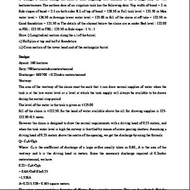
Tank Sluice 1z396k
December 2019 81
Acs Model Question Paper 1e455a
November 2019 131
Design And Drawing Of Irrigation Structures 4em5z
October 2019 86