1.3 Hydraulic Pumps 565g1
This document was ed by and they confirmed that they have the permission to share it. If you are author or own the copyright of this book, please report to us by using this report form. Report r6l17
Overview 4q3b3c
& View 1.3 Hydraulic Pumps as PDF for free.
More details 26j3b
- Words: 548
- Pages: 15
Operation of Hydraulic Pumps Section 1.3
Element 1.3
Komatsu Global Hydraulics
Pump Identification Gear Pump Identification.
1.3 Hydraulic Pumps
Komatsu Global Hydraulics
Pump Identification
1.3 Hydraulic Pumps
Komatsu Global Hydraulics
Pump Drives
Direct Coupling. Damper disc with spring type cushions. The hydraulic pump is coupled direct to the engine flywheel. The damper will absorb the engine vibrations and torque fluctuations
1.3 Hydraulic Pumps
Komatsu Global Hydraulics
Pump Drives
PTO Drive. Allows multiple pumps to be driven from the one drive. Specific drive gear ratio’s are calculated to ensure optimum pump speed is achieved
Pump couples into drive gear
1.3 Hydraulic Pumps
Komatsu Global Hydraulics
Cavitations Oil vapor bubble are created in the hydraulic pump due to a vacuum in the pump inlet. The bubbles are carried through the pump, as pressure increases they implode (collapse rapidly) when exposed to the high pressure.
Cavitation causes:
Restriction at the pump inlet. Intake hose too small. Reservoir too low.
High pressure will compress the bubbles creating extreme pressure causing the buzzing noise
A vacuum in pressure as oil is drawn into pump form the vapor or air bubbles.
1.3 Hydraulic Pumps
Komatsu Global Hydraulics
Aeration Aeration is air entering the hydraulic system on the inlet side of the hydraulic pump. The air when compressed at the pump causes air cushions through out the system. This results in loss of actuator control and over heating Cause of Aeration: Stable
Normal
1. Loss clamps around pump inlet pipe. 2. Loss hose fittings (return lines)
3. Fluid level low. Unstable movement
Aeration
1.3 Hydraulic Pumps
4. Return oil line to tank is below oil level. 5. Faulty pump shaft seal
Komatsu Global Hydraulics
Gear Pump
Basic Operation. The manufacturing clearances between the gears to the wear plates and centre housing is small enough to provide reasonable sealing. As the gears are rotated they picking up the oil from the reservoir, send it around the out-side of the pump, between the gears and housing. Pushing the oil out the other side creating a flow.
1.3 Hydraulic Pumps
Komatsu Global Hydraulics
Gear Pump Components
1
3
2
4
1. Drive gear: has an extended shaft to couple into the drive 2. Driven gear: meshes into the drive gear 3. Wear plate seals: stop oil bying from the high pressure to the low pressure 4. Wear plates: are pushed against the gears by out-put pressure reducing clearance between gears and wear-plates.
1.3 Hydraulic Pumps
Komatsu Global Hydraulics
Gear Pump Components
5
7 6
Gear Pump Components. 5. Housing: two end housings and centre housing. 6. Front Seal:
To stop air and dirt from being drawn into the hydraulic system. Stop hydraulic oil from transferring into the drive housing.
7. Housing clamp bolts. 1.3 Hydraulic Pumps
Komatsu Global Hydraulics
Gear Pump
Click on picture for short movie
1.3 Hydraulic Pumps
Komatsu Global Hydraulics
Variable Displacement Piston Pump
The Variable Displacement Pump length of stroke can be altered by changing the angle of the swash plate.
1.3 Hydraulic Pumps
Komatsu Global Hydraulics
Variable Displacement Piston Pump Components
Servo-piston Input shaft and cradle
Pistons
Impeller
Barrel 1.3 Hydraulic Pumps
Komatsu Global Hydraulics
Variable Displacement Piston Pump
Click on picture for short movie
1.3 Hydraulic Pumps
Komatsu Global Hydraulics
Pump Identification
END of Hydraulic Pumps
1.3 Hydraulic Pumps
Komatsu Global Hydraulics
Related Documents 171j1w

Fundamentals Of Hydraulic Pumps 5a3s2j
November 2019 73
1.3 Hydraulic Pumps 565g1
October 2021 0
Hydraulic Jet Pumps 6l29d
November 2019 34
Monarc Hydraulic Pumps 62182d
December 2019 31
Hydraulic Gear Pumps For Tractors 5482o
October 2020 0
Pumps 1c471i
December 2020 0More Documents from "Andika" 713x3e

Insertion Of Floral Leaves 2m1f1o
December 2019 54
Mekanisme Kerja Antibiotik 5x4d2e
July 2020 0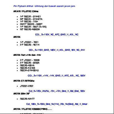
Persamaan Flyback Tv 6o3f6x
December 2019 254
Performa Mesin 1 2m1o5t
August 2020 0
1.3 Hydraulic Pumps 565g1
October 2021 0